Crestron TST-600-DSW-WMKT Installation guide
- Category
- Mobile device dock stations
- Type
- Installation guide
This manual is also suitable for

Crestron TST-600-DSW-TMK
& TST-600-DSW-WMKT
Trim Ring Kits for TST-600-DSW
Installation Guide

This document was prepared and written by the Technical Documentation department at:
The specific patents that cover Crestron products are listed at patents.crestron.com.
Crestron and the Crestron logo are either trademarks or registered trademarks of Crestron Electronics, Inc. in the United States
and/or other countries. Other trademarks, registered trademarks and trade names may be used in this document to refer to either the
entities claiming the marks and names or their products. Crestron disclaims any proprietary interest in the marks and names of others.
©2012 Crestron Electronics, Inc.

Crestron TST-600-DSW-TMK & TST-600-DSW-WMKT Trim Ring Kits
Contents
Trim Ring Kits for TST-600-DSW: TST-600-DSW-TMK & TST-600-DSW-WMKT 1
Description.................................................................................................................................1
Setup .......................................................................................................................................... 4
Supplied Hardware......................................................................................................4
Installation...................................................................................................................4
Resources.................................................................................................................................10
Reference Documents................................................................................................ 10
Further Inquiries ........................................................................................................ 10
Future Updates ..........................................................................................................10
Return and Warranty Policies .................................................................................................. 11
Merchandise Returns / Repair Service ......................................................................11
Crestron Limited Warranty........................................................................................11
Installation Guide – DOC. 7456A Contents • i


Crestron TST-600-DSW-TMK & TST-600-DSW-WMKT Trim Ring Kits
Trim Ring Kits for TST-600-DSW:
TST-600-DSW-TMK
& TST-600-DSW-WMKT
Description
Trim Ring Kits are the preferred method for mounting the Crestron
®
TST-600-DSW
Wall Mount Docking Station when a finished appearance within a neatly trimmed
cutout is required. This application is perfect for wallpapering.
NOTE: If mounting in a material other than drywall (for example, wood lectern,
concrete or rock) use the cutout template, available in the post-construction kit
TST-600-DSW-WMKT. For concrete and rock installations, allow for proper
ventilation before mounting the TST-600-DSW.
There are two Trim Ring Kits. The TST-600-DSW-TMK is a pre-construction
accessory. Pre-construction refers to framed walls prior to hanging drywall. This
accessory must be used with either the Pre-Construction Wall Mount Kit
(TST-600-DSW-PMK) or Back Box (TST-600-DSW-BB), both sold separately.
The TST-600-DSW-WMKT is a post-construction kit. Post-construction refers to
framed walls with drywall hung. This accessory is designed with a mounting plate so
it can be placed anywhere on a wall without the support of a stud. The mounting
plate is also ideal for installing the TST-600-DSW in a lectern.
NOTE: Since the TST-600-DSW contains moving parts, mounting on a stud offers
more support and is therefore highly recommended. Although Crestron offers the
post-construction TST-600-DSW-WMKT, a mounting option that is secured to a
stud, such as the TST-600-DSW-BB or TST-600-DSW-PMK is highly
recommended.
NOTE: If necessary, consult the latest version of the TST-600-DSW Operations &
Installation Guide (Doc. 7434) for a complete list of mounting options. The
document is available from the Crestron Web site (www.crestron.com/manuals
).
Installation Guide – DOC. 7456A Trim Ring Kits: TST-600-DSW-TMK & TST-600-DSW-WMKT • 1

Trim Ring Kits Crestron TST-600-DSW-TMK & TST-600-DSW-WMKT
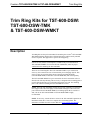
The dimensions of the TST-600-DSW-TMK and TST-600-DSW-WMKT are shown
in the following illustrations.
TST-600-DSW-TMK Overall Dimensions
9.28 in
(236 mm)
6.39 in
(163 mm)
1.04 in
(27 mm)
4.00 in
(102 mm)
0.52 in
(14 mm)
2.23 in
(57 mm)
TST-600-DSW-WMKT Overall Dimensions
10.31 in
(262 mm)
8.00 in
(204 mm)
0.06 in
(2 mm)
8.16 in
(208 mm)
6.35 in
(162 mm)
2 • Trim Ring Kits: TST-600-DSW-TMK & TST-600-DSW-WMKT Installation Guide – DOC. 7456A

Crestron TST-600-DSW-TMK & TST-600-DSW-WMKT Trim Ring Kits
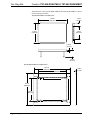
Drywall Cutout Template and Dimensions (Supplied with TST-600-DSW-WMKT Only)
TEMP LATE - 4010 0
C
L
CUT ALONG THIS EDG E
C
L
C
L
C
L
CUT
ALONG THIS EDG E
CUT ALONG THIS EDGE
CUT ALO NG THIS EDGE
THIS PIECE IS FOR CENTER LINE REFERENCE ONLY .
DO NOT USE THIS PIECE AS A CUTTING TEMPLATE.
9 1/16 in
(230 mm)
7 11/16 in
(196 mm)
6 1/8 in
(156 mm)
6 9/16 in
(167 mm)
Installation Guide – DOC. 7456A Trim Ring Kits: TST-600-DSW-TMK & TST-600-DSW-WMKT • 3

Trim Ring Kits Crestron TST-600-DSW-TMK & TST-600-DSW-WMKT
Setup
Supplied Hardware
The TST-600-DSW-TMK consists of a metal trim ring that attaches to the
TST-600-DSW-BB or TST-600-DSW-PMK. The TST-600-DSW-WMKT consists
of the trim ring found in the TST-600-DSW-TMK as well as a mounting plate, a set
of mounting screws and a cutout template.
The mounting plate provides the necessary support for installation in a wall, lectern,
podium or similar flat surface. An overlay cutout template (4506370) is supplied
which is similar to a frame, with the inner area of the frame in the shape of the
required opening. Refer to the illustration on page 3.
The hardware supplied with the TST-600-DSW-TMK and TST-600-DSW-WMKT is
listed in the following table.
Supplied Hardware for the TST-600-DSW-TMK and TST-600-DSW-WMKT
DESCRIPTION PART NUMBER QUANTITY
Metal, Plate, Ridge (Trim Ring) 2022808 1
Metal, Plate, Mounting
(TST-600-DSW-WMKT only)
2022811 1
Screw, #06-32 x 1 1/2”, Pan, Phil
(TST-600-DSW-WMKT only)
2007254 4
Overlay, Template, Wall Cutout
(TST-600-DSW-WMKT only)
4506370 1
Installation
This section provides an installation procedure for each Trim Ring Kit. The
“TST-600-DSW-TMK Procedure” starts below and the “TST-600-DSW-WMKT
Procedure” starts on page 6. Be sure to review each procedure before starting.
TST-600-DSW-TMK Procedure
This section provides the necessary steps for the assembly of the
TST-600-DSW-TMK for use with either the TST-600-DSW-BB or
TST-600-DSW-PMK. It is assumed the TST-600-DSW-BB or TST-600-DSW-PMK
has been secured to a stud according to the instructions in the latest version of its
Installation Guide (Doc. 7455 or Doc.7453 respectively). It is also assumed that
drywall is in place and a cutout is made in the drywall for installation of the
TST-600-DSW.
Complete the steps in the order provided. The only tool required and not supplied is
a level.
CAUTION: Allow an air gap of at least 12 inches (305 mm) in the wall cavity
above and below the TST-600-DSW for heat dissipation.
NOTE: The TST-600-DSW-TMK has been optimized for mounting in 5/8” (15
mm) drywall. It is possible to mount in 1/2” – 1” (13 mm – 25 mm) drywall without
issue. Thinner or thicker drywall causes issues with installation.
4 • Trim Ring Kits: TST-600-DSW-TMK & TST-600-DSW-WMKT Installation Guide – DOC. 7456A

Crestron TST-600-DSW-TMK & TST-600-DSW-WMKT Trim Ring Kits
NOTE: The illustrations in this procedure show the installation of the
TST-600-DSW-TMK with the TST-600-DSW-PMK. The procedure is identical with
the TST-600-DSW-BB.
NOTE: When installing into the TST-600-DSW-PMK, verify the 18 AWG bus wire
securing the cables for the TST-600-DSW Wall Mount Docking Station remains
attached.
1. Verify the cutout in the drywall is as level as possible.
2. Insert the symmetrical trim ring into the opening, as shown in the following
illustration.
Insert Trim Ring into Opening
Drywall
Trim Ring
(2022808)
IMPORTANT
Make drywall cutout as level and clean as possible.
The trim ring and mounting plate allow only minor
adjustments to the TST-600-DSW.
NOTE: The required TST-600-DSW-PMK or TST-600-DSW-BB is not shown.
3. When the trim ring is in position, bend the top two flanges of the ring
upward and the bottom two flanges downward.
• If mounting in the TST-600-DSW-PMK, bend the flanges
approximately 90 degrees.
• If mounting in the TST-600-DSW-BB, bend the flanges back as far as
they can go.
4. Run the necessary cables for the TST-600-DSW and secure them behind the
drywall.
5. The TST-600-DSW Wall Mount Docking Station can be installed using the
four tapped holes in the TST-600-DSW-PMK or TST-600-DSW-BB. Refer
to the latest version of the TST-600-DSW Operations & Installation Guide
(Doc. 7434) for details. Refer also to the following comprehensive
illustration.
Installation Guide – DOC. 7456A Trim Ring Kits: TST-600-DSW-TMK & TST-600-DSW-WMKT • 5

Trim Ring Kits Crestron TST-600-DSW-TMK & TST-600-DSW-WMKT
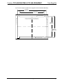
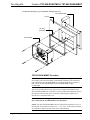
TST-600-DSW Mounting Using TST-600-DSW-TMK (Exploded View)
TST-600-DSW-PMK
Drywall
Trim Ring
(2022808)
TST-600-DSW
TST-600-DSW-WMKT Procedure
NOTE: Since the TST-600-DSW contains moving parts, mounting on a stud offers
more support and is therefore highly recommended. Although Crestron offers the
post-construction TST-600-DSW-WMKT, a mounting option that is secured to a
stud, such as the TST-600-DSW-BB or TST-600-DSW-PMK is highly
recommended.
This section provides the necessary steps for the assembly and installation of the
TST-600-DSW-WMKT into a wall. Review the procedure and complete the steps in
the order provided. The only tools or materials required and not supplied are a
drywall saw or equivalent and a level.
CAUTION: Allow an air gap of at least 12 inches (305 mm) in the wall cavity
above and below the TST-600-DSW for heat dissipation.
NOTE: The TST-600-DSW-WMKT has been optimized for mounting in 5/8” (15
mm) drywall. It is possible to mount in 1/2” – 1” (13 mm – 25 mm) drywall without
issue. Thinner or thicker drywall causes issues with installation.
6 • Trim Ring Kits: TST-600-DSW-TMK & TST-600-DSW-WMKT Installation Guide – DOC. 7456A

Crestron TST-600-DSW-TMK & TST-600-DSW-WMKT Trim Ring Kits
1. Locate an area on the wall that is free of miscellaneous wiring and studs.
2. Make a small hole near the middle of the designated site and verify the
location is suitable.
NOTE: Make the cutout as level and smooth as possible. The mounting plate allows
for only minor leveling adjustments. If a larger cutout is made accidentally, consider
purchasing the Crestron Mud Mount Kit, TST-600-DSW-MMK. Together with the
mounting plate supplied with the TST-600-DSW-WMKT, it provides a
cost-effective means of correction. Essentially, the combination of these two kits
makes up the Crestron Mud Mount Kit for the wall, TST-600-DSW-WMKM.
Simply follow the “TST-600-DSW-WMKM Procedure” in the latest version of the
TST-600-DSW-MMK & TST-600-DSW-WMKM Installation Guide (Doc. 7457).
3. Use the drywall saw or equivalent, the level and the provided cutout
template to produce a level and accurate cutout in the drywall.
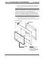
4. Insert the trim ring into the opening, as shown in the following illustration.
Insert Trim Ring into Opening
Drywall
Trim Ring
(2022808)
Mounting Plate
(2022811)
.
IMPORTANT
Make drywall cutout as level
and clean as possible.
The trim ring and mounting plate
allow only minor adjustments
to the TST-600- DSW.
Installation Guide – DOC. 7456A Trim Ring Kits: TST-600-DSW-TMK & TST-600-DSW-WMKT • 7

Trim Ring Kits Crestron TST-600-DSW-TMK & TST-600-DSW-WMKT
5. Carefully pass the mounting plate through the opening and hold it against
the interior surface of the drywall.
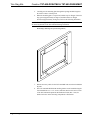
6. When the mounting plate is in position, bend the top two flanges of the trim
ring upward (approximately 90 degrees) and the bottom two flanges
downward (approximately 90 degrees). Refer to the following illustration.
NOTE: The mounting plate has a slight amount of play. This is normal and allows
for minor adjustments to the TST-600-DSW during installation.
Bend Flanges (Showing One of Four Flanges Bent)
7. Run the necessary cables for the TST-600-DSW and secure them behind the
drywall.
8. The TST-600-DSW Wall Mount Docking Station can be installed using the
four included #06-32 x 1 1/2” screws (2007254). Refer to the latest version
of the TST-600-DSW Operations & Installation Guide (Doc. 7434) for
details. Refer also to the following comprehensive illustration.
8 • Trim Ring Kits: TST-600-DSW-TMK & TST-600-DSW-WMKT Installation Guide – DOC. 7456A

Crestron TST-600-DSW-TMK & TST-600-DSW-WMKT Trim Ring Kits
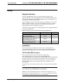
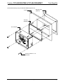
TST-600-DSW Mounting Using TST-600-DSW-WMKT (Exploded View)
Drywall
Trim Ring
(2022808)
TST-600-DSW
Mounting Plate
(2022811)
Screws (4) #06-32 x 1 1/2”
(2007254)
Installation Guide – DOC. 7456A Trim Ring Kits: TST-600-DSW-TMK & TST-600-DSW-WMKT • 9

Trim Ring Kits Crestron TST-600-DSW-TMK & TST-600-DSW-WMKT
Resources
Reference Documents
The latest version of all documents mentioned within the guide can be obtained from
the Crestron Web site (www.crestron.com/manuals).
List of Related Reference Documents
DOCUMENT TITLE
TST-600-DSW Wall Mount Docking Station for TST-600
TST-600-DSW-BB Back Box for TST-600-DSW
TST-600-DSW-MMK & TST-600-DSW-WMKM Mud Mount Kits for TST-600-DSW
TST-600-DSW-PMK Pre-Construction Wall Mount Kit for the TST-600-DSW
Further Inquiries
To locate specific information or resolve questions after reviewing this guide,
contact Crestron's True Blue Support at 1-888-CRESTRON [1-888-273-7876] or
refer to the listing of Crestron worldwide offices on the Crestron Web site
(www.crestron.com/offices) for assistance within a particular geographic region.
To post a question about Crestron products, log onto the Online Help section of the
Crestron Web site (www.crestron.com/onlinehelp
). First-time users must establish a
user account to fully benefit from all available features.
Future Updates
As Crestron improves functions, adds new features and extends the capabilities of
the TST-600-DSW-TMK and TST-600-DSW-WMKT, additional information may
be made available as manual updates. These updates are solely electronic and serve
as intermediary supplements prior to the release of a complete technical
documentation revision.
Check the Crestron Web site periodically for manual update availability and its
relevance. Updates are identified as an “Addendum” in the Download column.
10 • Trim Ring Kits: TST-600-DSW-TMK & TST-600-DSW-WMKT Installation Guide – DOC. 7456A

Crestron TST-600-DSW-TMK & TST-600-DSW-WMKT Trim Ring Kits
Return and Warranty Policies
Merchandise Returns / Repair Service
1. No merchandise may be returned for credit, exchange or service without prior authorization from
Crestron. To obtain warranty service for Crestron products, contact an authorized Crestron dealer.
Only authorized Crestron dealers may contact the factory and request an RMA (Return
Merchandise Authorization) number. Enclose a note specifying the nature of the problem, name
and phone number of contact person, RMA number and return address.
2. Products may be returned for credit, exchange or service with a Crestron Return Merchandise
Authorization (RMA) number. Authorized returns must be shipped freight prepaid to Crestron, 6
Volvo Drive, Rockleigh, N.J. or its authorized subsidiaries, with RMA number clearly marked on
the outside of all cartons. Shipments arriving freight collect or without an RMA number shall be
subject to refusal. Crestron reserves the right in its sole and absolute discretion to charge a 15%
restocking fee plus shipping costs on any products returned with an RMA.
3. Return freight charges following repair of items under warranty shall be paid by Crestron,
shipping by standard ground carrier. In the event repairs are found to be non-warranty, return
freight costs shall be paid by the purchaser.
Crestron Limited Warranty
Crestron Electronics, Inc. warrants its products to be free from manufacturing defects in materials and
workmanship under normal use for a period of three (3) years from the date of purchase from Crestron,
with the following exceptions: disk drives and any other moving or rotating mechanical parts, pan/tilt heads
and power supplies are covered for a period of one (1) year; touch screen display and overlay components
are covered for 90 days; batteries and incandescent lamps are not covered.
This warranty extends to products purchased directly from Crestron or an authorized Crestron dealer.
Purchasers should inquire of the dealer regarding the nature and extent of the dealer's warranty, if any.
Crestron shall not be liable to honor the terms of this warranty if the product has been used in any
application other than that for which it was intended or if it has been subjected to misuse, accidental
damage, modification or improper installation procedures. Furthermore, this warranty does not cover any
product that has had the serial number altered, defaced or removed.
This warranty shall be the sole and exclusive remedy to the original purchaser. In no event shall Crestron
be liable for incidental or consequential damages of any kind (property or economic damages inclusive)
arising from the sale or use of this equipment. Crestron is not liable for any claim made by a third party or
made by the purchaser for a third party.
Crestron shall, at its option, repair or replace any product found defective, without charge for parts or labor.
Repaired or replaced equipment and parts supplied under this warranty shall be covered only by the
unexpired portion of the warranty.
Except as expressly set forth in this warranty, Crestron makes no other warranties, expressed or implied,
nor authorizes any other party to offer any warranty, including any implied warranties of merchantability or
fitness for a particular purpose. Any implied warranties that may be imposed by law are limited to the terms
of this limited warranty. This warranty statement supersedes all previous warranties.
Installation Guide – DOC. 7456A Trim Ring Kits: TST-600-DSW-TMK & TST-600-DSW-WMKT • 11

Crestron Electronics, Inc. Installation Guide – DOC. 7456A
15 Volvo Drive Rockleigh, NJ 07647 (2035130)
Tel: 888.CRESTRON 12.12
Fax: 201.767.7576 Specifications subject to
www.crestron.com change without notice.
-
 1
1
-
 2
2
-
 3
3
-
 4
4
-
 5
5
-
 6
6
-
 7
7
-
 8
8
-
 9
9
-
 10
10
-
 11
11
-
 12
12
-
 13
13
-
 14
14
-
 15
15
-
 16
16


Crestron TST-600-DSW-WMKT Installation guide
- Category
- Mobile device dock stations
- Type
- Installation guide
- This manual is also suitable for
Ask a question and I''ll find the answer in the document
Finding information in a document is now easier with AI
Related papers
-
Crestron TST-600-MMK Installation guide
-
-
-
-
-
-
-
-
Crestron WMKM-4L User manual
-
Other documents
-
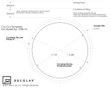 DECOLAV 1000TU Cutout Template
-
 Crestron electronic TPS-15L User manual
-
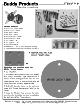 Buddy Products 7434-4 Operating instructions
-
Tannoy PMK 5 IW Quick start guide
-
Shinko DSW-100-TxHx User manual
-
-
-
Danfoss TMK User guide
-
-
Hafele 422.29.350 Operating instructions


