Page is loading ...

INSTALLATION MANUAL
2nd Revision – February 24, 2021
EKLoop
Connect
CONTROLLER

- 2 -
This product is intended for installation only by expert users. Please
consult with a qualified technician for installation. Improper installation
may result in damage to your equipment. EK Water Blocks assumes no
liability whatsoever, expressed or implied, for the use of these products,
nor their installation. The following instructions are subject to change
without notice. Please visit our web site at www. ekwb.com for updates.
Before installation of this product please read important notice,
disclosure and warranty conditions printed on the back of the box.
This guide details the physical installation of your EK-Loop
Connect controller and all of the standard connections which may
be used to link your components.

- 3 -
TABLE OF CONTENT
INSTALLING THE EK-LOOP CONNECT IN TO THE CHASSIS 4
CONNECTING THE FAN-S 5
CONNECTING THE D-RGB LED 6
TEMPERATURE SENSOR 6
INSTALLING THE EK-LOOP CONNECT - FLOW METER 7
INSTALLING THE EK-LOOP CONNECT - LEVEL SENSOR 8
CONNECTING THE USB CABLE 10
CONNECTING THE POWER ADAPTER 11
SOFTWARE 11
SUPPORT AND SERVICE 12
SOCIAL MEDIA 12

- 4 -
INSTALLING THE EK-LOOP CONNECT IN TO THE CHASSIS
STEP 1
Remove the desired 2.5” SSD tray
STEP 1
STEP 2
Install the EK-Loop Connect on to the metal plate using M3X5
DIN7985 Screws.
STEP 2
EK- LOOP
CONNECT
2.5” SSD
T R AY
M3x5
DIN7985
SCREW

- 5 -
STEP 3
Final Installation
Attach the metal plate with pre-assembled EK-Loop Connect on to
the case.
STEP 3
CONNECTING THE FAN-S
The controller is compatible with 4-pin PWM Fans, 3-pin Fans may
be used however it will not be possible to adjust the speed. Insert
the 4-pin Fan connectors as shown below to the 6 Fan headers
marked F1-F6.
Fan Splitters may be used to connect multiple Fans to one
header. EK recommends the use of Splitters with separate power
connectors for 4 or more fans. Do not connect splitters in series!
FAN
HEADERS
4-PIN PWM FAN
CONNECTOR
FAN HEADER

- 6 -
CONNECTING THE D-RGB LED
There are 6 Lighting headers marked with L1-L6, these headers
are compatible only with 5V D-RGB products and LED strips! Make
sure that the arrows are aligned.
D-RGB Splitters may be used to connect multiple D-RGB products
to a single header. Do not connect splitters in series!
3-PIN
CONNECTOR
+5V D-RGB
TEMPERATURE SENSOR
Optionally up to 3 temparature sensors may be installed to the
headers marked T1-T3.
TEMPERATURE
SENSOR
HEADERS
2- PIN TEMPERATURE
SENSOR CONNECTOR
D-RGB HEADERS
EK - LOOP CONNECT
TEMPERATURE SENSOR
HEADER

- 7 -
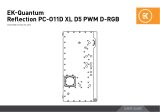
INSTALLING THE EK-LOOP CONNECT - FLOW METER
STEP 1
The Flow Meter can be mounted anywhere in the loop. Check the
direction of the coolant flow and use the correct INLET port as
marked in the image.
STEP 1
INLET
FLOW
DIRECTION
FLOW
DIRECTION
FLOW
DIRECTION
FLOW
DIRECTION
INLET
CABLE LENGTH: 500 mm
OUTLET
OUTLET
EK FITTING

- 8 -
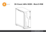
INSTALLING THE EK-LOOP CONNECT - LEVEL SENSOR
CABLE LENGTH: 500 mm
STEP 2
Connect the Flow Meter cable to the FLO port on the EK-Loop
Connect.
EK-Loop Connect software is by default set to show
the correct flow rate when combined with EK-Loop
Connect - Flow Meter (No.Signals/Liter=80). If you are
using a flow meter from another manufacturer, the
setting for displaying the corresponding flow must be
calibrated within the EK-Loop Connect software.
3-PIN FLOW METER
CONNECTOR
STEP 2

- 9 -
STEP 1
Mount the Level Sensor on the appropriate tube-shaped reservoir.
Adjust the height so the detection zone can be set correctly. EK-Loop
Connect will trigger a warning in case the coolant level drops below
the detection zone region.
STEP 1
STEP 2
Connect the Level Sensor cable to the LVL port on EK-Loop Connect.
4-PIN LEVEL SENSOR
CONNECTOR
STEP 2
SCREW FOR
SENSOR
SENSITIVITY
ADJUSTMENTS
SENSOR’S
DETECTION
ZONE

- 10 -
CONNECTING THE USB CABLE
EK-Loop Connect must be linked to the motherboard using the
supplied Internal USB 2.0 cable. Connect the 9-pin end to a USB2.0
header on the motherboard, pay attention to the orientaiton of the
missing pin.
The other end of the USB cable should be plugged into the Connects
USB port.
USB HEADER
4-PIN USB
CONNECTOR
9-PIN USB CONNECTOR
USB 2.0 INTERNAL HEADER

- 11 -
CONNECTING THE POWER ADAPTER
Finally plug in the Molex power connector to the PWR port using
either a Molex connector directly from your PSU or the supplied 2x
SATA Power adapter.
SOFTWARE
Now that physicall installation of the EK-Loop Connect is complete
you may install software and continue confirguring all connected
components.
MOLEX POWER HEADER
MOLEX POWER CONNECTOR

For assistance please contact:
http://support.ekwb.com/
EKWB d.o.o.
Pod lipami 18
1218 Komenda
Slovenia - EU
EKWaterBlocks
@EKWaterBlocks
ekwaterblocks
ekwaterblocks
EKWBofficial
SUPPORT AND SERVICE
SOCIAL MEDIA
/