Page is loading ...

81iHigh
/
Low Level
Conversion Instructions
Part Number 112946-00
25Mar2016

2 81i High/Low Level Conversion Instructions Thermo Fisher Scientific

Thermo Fisher Scientific 81i High/Low Level Conversion Instructions 3
Note This procedure assumes work is to be performed on one (1) each
fully functional and upgraded 81i Mercury (Hg) Calibrator. ▲
Note Customer installations vary; this instruction uses general terminology
to facilitate completion. ▲
Unpack the box containing the Conversion Kit (114980-00 for High Level
and 112945-00 for Low Level) and make sure that the package contains the
following components:
● 1 Line Chiller Assembly (102172-00)
● 1 Controller, Mass Flow
● 100 sccm for High Level (102628-00)
● 5 sccm for Low Level (112775-00)
● 1 Transducer, High Pressure (111899-00)
● 1 Kynar Cap (114979-00)
● 1 Kynar Tee (10131)
● 2 Kynar Reducer (114977-00)
● 3 PTFE Tubing, 1/4-inch D x 1.75-inch L (4206)
● PTFE Tubing, 1/8-inch D x 6-inch L (5510)
● PTFE Tubing, 1/8-inch D x 8-inch L (5510)
● PTFE Tubing, 1/4-inch D x 3.25-inch L (4206)
● 1 Instructions for 81i High/Low Conversion (112946-00)
● 1 Label, Conversion Compliance 81i
● High Level (114982-00)
● Low Level (112984-00)
● 1 Label, Bubble
● High Level (102516-02)
● Low Level (102516-01)
Equipment
Required/Provided
for Installation

4 81i High/Low Level Conversion Instructions Thermo Fisher Scientific
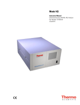
Figure 1. Installed Components
Follow the steps below before beginning installation.
1. Remove top cover to 81i Hg Calibrator.
2. Remove air pressure to 81i Hg Calibrator. Monitor pressure gauge on
81i regulator/gauge assembly; proceed when pressure drops to zero psi.
3. Shut OFF 81i front panel power switch.
WARNING Implementation of this conversion kit will invalidate any
existing certification due to the required recalibration of major
components. Refer to the Model 81i Instruction Manual for
manufacturer’s disclosure. ▲
Equipment Damage High Pressure Transducer Assembly 111899-00 can
be damaged by small amounts of static electricity. A properly ground
antistatic wrist strap must be worn while handling any internal component.
If an antistatic wrist strap is not available, be sure to touch the instrument
chassis before unpacking transducer or touching any internal components.
When the instrument is unplugged, the chassis is not at earth ground. ▲
Preparation
Pressure Transducer Tubing
Cooler 1/8” Tubing w/sleeve
New MFC
Reducer Tee
PTFE Tubing 3.25” L

Thermo Fisher Scientific 81i High/Low Level Conversion Instructions 5
Perform the following in sequence:
4. View pressure gauge on 81i regulator/gauge assembly; ensure it reads
zero psi before proceeding.
5. Remove the Mass Flow Controller, Hg Line Chiller, and Pressure
Transducer Assemblies. Refer to Model 81i Instruction Manual
103068-00, Chapter 7, Servicing.
Use the following procedure to remove the mass flow controller (MFC).
Equipment Required:
Philips screwdrivers, #1 and #2
Wrench, 9/16-inch
Wrench, 7/16-inch
Wrench, 8/8-inch
Flat blade screwdriver
a. Disconnect the electrical connectors from the top of the 50 sccm
MFC and the fan.
b. Disconnect the pneumatics from the 50 sccm MFC.
c. Loosen the four captive retaining screws securing the MFC
assembly to the base and lift the assembly off.
d. Turn the assembly over and remove the two retaining screws from
the 50 sccm MFC.
Use the following procedure to remove the cooler assembly.
Equipment Required:
Wrench, 7/16-inch
Wrench, 5/8-inch
Nut driver, 1/4-inch
Philips screwdriver
Wire cutters
Removal
Removing the Mass Flow
Controller
Removing the Cooler
Assembly

6 81i High/Low Level Conversion Instructions Thermo Fisher Scientific
a. Pull the power connector off the cooler fan, and remove pneumatic
and electrical connections. Cut any tie straps necessary.
b. Remove the four screws securing the cooler shroud and remove the
shroud.
c. Remove the four screws holding cooler to floor plate and remove
the cooler assembly.
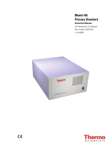
Figure 2. Removing the Cooler
Note The Mercury Line Chiller Assembly contains Mercury. This
assembly and any tubing removed during this procedure are to be properly
disposed of or reused in accordance with local directives. ▲
Use the following procedure to remove the pressure transducer assembly.
Equipment Required:
#1 Philips screwdriver
a. Disconnect plumbing from the pressure transducer assembly. Note
the plumbing connections to facilitate reconnection.
b. Disconnect the pressure transducer cable from the measurement
interface board.
c. Loosen the two pressure transducer assembly retaining screws and
remove the pressure transducer assembly by sliding it down then
taking it out.
d. Install Kynar cap onto open fitting, tighten.
Removing the Pressure
Transducer Assembly
Cooler Floor Plate Screws (4)
Shroud Screws (4)
On Rear Panel
Shroud

Thermo Fisher Scientific 81i High/Low Level Conversion Instructions 7
Figure 3. Removing the Pressure Transducer Assembly
Perform the following in sequence:
6. Install the new High Pressure Transducer. Refer to the Model 81i
Instruction Manual 103068-00, Chapter 7, Servicing.
Use the following procedure to install the new high pressure transducer.
a. Install the new pressure transducer assembly by following previous
steps in reverse. Refer to “Removing the Pressure Transducer” in
this document.
7. Install the new Chiller Assembly. Refer to the Model 81i Instruction
Manual 103068-00, Chapter 7, Servicing.
Use the following procedure to install the new chiller assembly.
Installation
Installing the High
Pressure Transducer
Installing the Chiller
Assembly
Pressure Transducer Assy
Retaining Screws (2)

8 81i High/Low Level Conversion Instructions Thermo Fisher Scientific
a. Install the new chiller by following previous steps in reverse. Be sure
to connect the fan power cable before installing the shroud. Refer
to “Removing the Cooler” in this document.
8. Install the Mass Flow Controller Assembly. Refer to the Model 81i
Instruction Manual 103068-00, Chapter 7, Servicing.
Use the following procedure to install the new mass flow controller (MFC).
a. Install the new 100 sccm MFC for high level and the new 5 sccm
MFC for low level by following the previous steps in reverse. Refer
to “Removing the Mass Flow Controller” in this document, and
Figure 1.
b. Connect the 1/8-inch tubing from output of MFC to reducing
union input. Connect other end of reducing union to one end of
PTFE tubing 1/4 x 3.25-inch L.
c. Connect Kynar tee to the other end of PTFE tubing 1/4 x 3.25-
inch L. Note arrow direction pointing to chiller.
d. Take 1.75-inch L of 1/4-inch tubing from tee into chiller assembly.
e. Reuse flexible Silastic tubing and cut to 3.5-inch.
f. Route from Kynar tee at chiller input to transducer.
g. Tighten all nuts.
9. Replace bubble label on front panel with new bubble label and place
compliance label as shown.
TO HIGH-LEVEL OPERATION
i
UPGRADED
Figure 4. Conversion Label
Installing the Mass Flow
Controller Assembly

Thermo Fisher Scientific 81i High/Low Level Conversion Instructions 9
10. Perform instrument leak test and calibration.
Use the following procedure to perform the leak test. Refer to the Model
81i Instruction Manual 103068-00, Chapter 5, Preventive Maintenance.
a. Cap the following ports on the instrument’s rear panel:
EXHAUST
ZERO AIR
CAL GAS
b. Remove the check valve and temporarily replace the check valve
with a union connector.
c. Connect an external pump (Thermo part number 101426-00 or
equivalent) to the PROBE bulkhead connector on the instrument’s
rear panel.
d. Connect a 500 cc flow meter to the pressure side of the pump.
e. Turn the pump ON.
f. Flow should decrease to less than 10 cc/min. Allow ten minutes to
evacuate the calibrator lines.
g. Remove the union connector installed in Step b, and replace the
check valve in the proper orientation, arrow pointing toward front
panel.
h. Verify that the check valve is functioning correctly.
i. Connect a pressure gauge to the PROBE bulkhead.
ii. In the Instrument Controls menu, select Gas Mode > Orifice
Zero.
The gauge should not read greater than 12 psig. If the reading
is greater than 12 psig, check the plumbing and valve set point.
To adjust, refer to document no. MS-CRD-0047 at:
www.swagelok.com
Use the following procedure to calibrate the pressure transducer. Refer to
the Model 81i Instruction Manual 103068-00, Chapter 7, Servicing.
Note Do not try to calibrate the pressure transducer unless the atmospheric
pressure is accurate and NIST Traceable. ▲
Leak Test
Pressure Transducer
Calibration

10 81i High/Low Level Conversion Instructions Thermo Fisher Scientific
Equipment Required:
Vacuum pump
a. Disconnect the tubing from the pressure transducer and connect a
vacuum pump known to produce a vacuum less than 1 mmHg.
b. From the Main Menu, press to scroll to Service > press
> to scroll to Pressure Calibration > and press .
The Pressure Sensor Cal menu appears.
c. At the Pressure Sensor Cal screen, press to select Zero.
The Calibrate Pressure Zero screen appears.
d. Wait at least 30 seconds for the zero reading to stabilize, then press
to save the zero pressure value.
e. Disconnect the pump from the pressure transducer.
f. Press to return to the Pressure Sensor Cal screen.
g. At the Pressure Sensor Cal screen, press to select
Span.
h. The Calibrate Pressure Span screen appears.
i. Wait at least 30 seconds for the ambient reading to stabilize, use
and to enter the known barometric
pressure, and press to save the pressure value.
j. Reconnect the Silastic tubing to the pressure transducer.
In order to calibrate the mass flow meter section of the zero or gas mass
flow controller, a NIST traceable flow meter is required. The term
calibration means determining the actual flow versus the flow setting for
seven equally spaced flows along the range of the device. The Model 81i
then corrects the output according to an internal algorithm.
Calibration may be done with a properly calibrated flow meter. For the
most accurate calibration procedure, use a volumetric NIST traceable
calibrator with the following step-by-step calibration procedure. Refer to
the Model 81i Instruction Manual 103068-00, Chapter 4, Calibration.
a. Connect a source of clean, dry air to the inlet of the mass flow
controller.
b. Measure barometric pressure and room temperature.
c. Connect a suitable flow meter to the mass flow controller outlet.
Mass Flow Controller
Calibration

Thermo Fisher Scientific 81i High/Low Level Conversion Instructions 11
d. Set Model 81i to Hg Flow or Zero Air Flow Calibration. Refer to
the Model 81i Instruction Manual 103068-00, Chapter 3,
Operation.
e. Set flow controller to 95 percent of full scale, then wait until flow
meter reading stabilizes.
f. Enter the flow meter reading using the flow input screen.
g. Repeat Steps e and f for the remaining flow settings.
If you encounter a flow controller malfunction, contact Thermo
Fisher Scientific.
11. These changes will require NIST traceability certification. Please
contact Thermo Fisher Scientific Customer Service.
For additional assistance, service is available from exclusive distributors
worldwide. Contact one of the phone numbers below for product support
and technical information or visit us on the web at:
www.thermoscientific.com/aqi.
1-800-282-0430 Toll Free
1-508-520-0430 International
Service Locations

12 81i High/Low Level Conversion Instructions Thermo Fisher Scientific
© 2014 Thermo Fisher Scientific Inc. All rights reserved.
Specifications, terms and pricing are subject to change. Not all products are
available in all countries. Please consult your local sales representative for
details.
Thermo Fisher Scientific
Air Quality Instruments
27 Forge Parkway
Franklin, MA 02038
1-508-520-0430
www.thermoscientific.com/aqi
/