Moxa UC-8540 Series Quick setup guide

Type
Quick setup guide

Moxa UC-8540 Series is a programmable communication-centric gateway offering various communication interfaces like Ethernet, serial, and wireless communication, making it suitable for building wireless communication infrastructure with 802.11a/b/g/n/ac and LTE data transmission. It features multiple wireless interfaces, including Wi-Fi and cellular modules, providing reliable connectivity in various applications.

Moxa UC-8540 Series is a programmable communication-centric gateway offering various communication interfaces like Ethernet, serial, and wireless communication, making it suitable for building wireless communication infrastructure with 802.11a/b/g/n/ac and LTE data transmission. It features multiple wireless interfaces, including Wi-Fi and cellular modules, providing reliable connectivity in various applications.

P/N: 1802085400011
*1802085400011*
UC-8540 Series
Quick Installation Guide
Version 1.1, January 2021
Technical Support Contact Information
www.moxa.com/support
2021 Moxa Inc. All rights reserved.
- 2 -
Overview
The UC-8540 Series computer is a programmable communication-centric
gateway offering a rich variety of communication interfaces, such as
Ethernet, serial, and wireless communication. This EN 50155-compliant
computer is built for rail applications and comes with multiple wireless
interfaces making it an ideal choice for building wireless communication
infrastructure with 802.11a/b/g/n/ac and LTE data transmission.
Model Names and Package Checklist
The UC-8540 Series includes the following models:
Available
Models
Operating
Temperature
Conformal
Coating
UC-8540-LX -25 to 55°C
(-13 to 131°F)
UC-8540-T-LX
-40 to 70°C
(-40 to 158°F)
UC-8540-T-CT-LX
-40 to 70°C
(-40 to 158°F)
Before you install the UC-8540 Series computer, ensure that the package
contains the following items:
UC-8540 Series computer
Mounting kits
CBL-4PINDB9F-100: 4-pin pin header to DB9 female console port
cable, 100 cm
Quick installation guide (printed)
Warranty card
Appearance
Front View
- 3 -
Side View
Bottom View
LED Indicators
Refer to the following table for the LED indicator definitions.
LED Name
Status
Function
P
Green
Power is on
Off
No power input
R
Green
System is ready
Off
System is booting up, OS boot-up failure, or
other system initialization error
Ethernet
(located next
to the
Ethernet
ports)
Green Steady On: 100 Mbps Ethernet link
Blinking: Data transmission is in progress
Yellow
Steady On: 1000 Mbps Ethernet link
Blinking: Data transmission is in progress
Off
Data transmission speed at 10 Mbps or the data
cable is not connected
Serial
Green
Tx: Data transmission is in progress
Yellow
Rx: Receiving data
Off
No operation on the serial ports
S
Green
Data is being accessed from either the eMMC or
the mSATA module
Off
No data is being accessed
PGM
Red
Programmable LED for user-defined function
Wireless
Green
The number of glowing LEDs indicate the
wireless signal strength as follows:
3 Green: Excellent
2 Green: Good
1 Green: Poor
Off
No wireless signal
- 4 -
Installing the Computer
Wall or Desk Mounting
Use two screws per side to mount the UC-8540 computer on a wall or
desk.
Wall Mounting
Fasten the screws at back side of UC-8540
Desk Mounting
Fasten the screws at bottom side of UC-8540
Wiring Requirements
Be sure to read and follow these common safety precautions before
proceeding with the installation of any electronic device:
Use separate paths to route wiring for power and devices. If power
wiring and device wiring paths must cross, make sure the wires are
perpendicular at the intersection point.
NOTE
Do not run signal or communication wiring together with power
wiring in the same wire conduit. To avoid interference, wires with
different signal characteristics should be routed separately.
Use the type of signal transmitted through a wire to determine which
wires should be kept separate. The rule of thumb is that wiring that
shares similar electrical characteristics can be bundled together.
Keep input wiring and output wiring separate.
It is advisable to label the wiring to all devices in the system.
- 5 -
ATTENTION
Safety First!
Be sure to disconnect the power cord before installing and/or
wiring your UC
-8540 computer.
Wiring Caution!
Calculate the maximum possible current in each power wire and
common wire. Observe all electrical codes dictating the
maximum current allowable for each wire size. If the current goes
above the maximum ratings, the wiring could overheat, causing
serious damage to your equ
ipment.
Temperature Caution!
Be careful when handling the unit. When the unit is plugged in,
the internal components generate heat, and consequently the
outer casing may feel hot to the touch.
Connecting the Power
Connect the 24 to 110 VDC power line with M12 A-coded connector to the
UC-8540 computer. If the power is supplied properly, the “P” LED will
glow a solid green after a 25 to 30-second delay. The power input location
and pin definition are shown in the following figures:
Grounding the Unit
Grounding and wire routing help limit the effects of noise due to
electromagnetic interference (EMI). Run the ground connection from the
ground screw to the grounding surface prior to connecting the power.
Please note that this product is intended to be mounted on a
well-grounded mounting surface, such as a metal panel. The grounding
connected is provided and located on the front panel. Connect the
grounding wire to an appropriate grounded metal surface.
Power Input
(24
-110 VDC, M12)
Grounding
Connector
- 6 -
Connecting to the Network
The pin assignments for the UC-8540 computer’s Ethernet port are shown
in the following figure. If you are using your own Ethernet cable, make
sure that you match the pin assignment on the connector of the Ethernet
cable to the pin assignment shown below:
Connecting a Serial Device
Use a serial cable to connect your serial device to the computer’s serial
port. Serial ports uses DB9 connector and can be configured for RS-232,
RS-422, or RS-485 communication. The pin location and assignment are
shown in the following diagrams:
Pin
RS-232
RS-422
RS-485 (4-wire)
RS-485 (2-wire)
1
DCD
TxDA(-)
TxDA(-)
2
RxD
TxDB(+)
TxDB(+)
3
TxD
RxDB(+)
RxDB(+)
DataB(+)
4
DTR
RxDA(-)
RxDA(-)
DataA(-)
5
GND
GND
GND
GND
6
DSR
7
RTS
8
CTS
LAN Ports x 2, LEDs x 4
(10/100/1000 Mbps, M12)
Serial Ports
(RS-232/422/485, DB9)
- 7 -
Connecting a USB Device
The UC-8540 computer is provided with a USB 3.0 port on the front panel
for connecting a USB device.
Connecting the Wi-Fi/Cellular Module and Antenna
The UC-8540 computer is provided with two sets of QMA antenna holes
for installing antennas for the Wi-Fi and cellular modules. Unfasten the
two screws on the side panel and lift up the panel to check the location of
the Wi-Fi/cellular module sockets.
Socket Name
Usage
Cellular
Cellular module
Wi-Fi
Wi-Fi module
You will need to install the SIM cards for the cellular modules in the
designated SIM-card slots 1 and 2.
USB
Port x 1
(
USB 3.0, type A)
SIM Slots x 2
(Micro SIM)
- 8 -
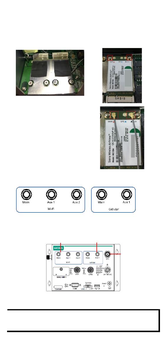
To install a wireless (Wi-Fi/cellular) module, do the following:
1.
The thermal pads come attached
to the wireless module. Remove
the plastic protective film on the
thermal pads.
2.
Insert the wireless module in
the designated socket and
tighten the two screws on the
module.
3. Attach the flat end of the antenna
cable to the connector marked
MAIN on the module. Follow the
procedure described above to
attach the AUX antenna cable.
If your UC-8540 is
not standalone
GPS version, you can attach the
GPS antenna cable to the
connector marked GSP on the
module.
Refer to the following figure provided on the front panel to identify the
antenna mounting holes for the wireless modules.
4. Connect the antennas to the connectors on the front panel. Refer to
the following figure for the specific location of each antenna
connector, including a connector for a GPS antenna.
Use the procedure described above to install other Wi-Fi or cellular
modules.
NOTE
The Wi-Fi module installed in the socket requires three antennas.
Make sure all three antennas are installed and secured properly
before you use the module.
Wi-Fi Antenna
QMA Connectors x 3
Cellular Antenna
QMA Connectors x 2
GPS Antenna
TNC Connector
- 9 -
Installing SIM Cards
Cellular module supports 2 Micro SIM cards. To install Micro SIM cards for
the cellular modules, do the following:
1. Open the case of the Micro
SIM card socket.
2. Push down the Micro SIM-card
into the socket by correct
direction. Push
again to remove
inserted SIM-card.
Installing the mSATA Module & Replacing RTC
Battery
The UC-8540 computer is provided with one storage socket for installing
an mSATA module and a replaceable RTC battery. To install the mSATA
module, do the following:
1. Unfasten the case of bottom side to locate mSATA socket.
2. Insert the mSATA module onto the socket and fasten the two screws
on the module to secure the module.
3. RTC battery (BR2032) is located at the side of mSATA socket.
  • Page 1 1
  • Page 2 2
  • Page 3 3
  • Page 4 4
  • Page 5 5
  • Page 6 6
  • Page 7 7
  • Page 8 8
  • Page 9 9

Moxa UC-8540 Series Quick setup guide

Type
Quick setup guide

Moxa UC-8540 Series is a programmable communication-centric gateway offering various communication interfaces like Ethernet, serial, and wireless communication, making it suitable for building wireless communication infrastructure with 802.11a/b/g/n/ac and LTE data transmission. It features multiple wireless interfaces, including Wi-Fi and cellular modules, providing reliable connectivity in various applications.

Ask a question and I''ll find the answer in the document

Finding information in a document is now easier with AI