Page is loading ...

Document in original language | 208766 · A003
Topvex SoftCooler SR09, SR11
Access control system
Operation and Maintenance Instructions GB

208766 | A003

208766 | A003
Contents
1 Warnings.......................................................1
2 Product description..........................................1
2.1 Components .........................................1
2.2 Electrical cabinet ....................................2
3 Installing the unit.............................................3
3.1 Installation............................................3
4 Refrigerant Control/Reporting ............................3
5 Function Description ........................................4
5.1 General................................................4
5.2 Power control........................................4
5.3 Power limitation.....................................4
6 Cooling flow chart ...........................................5
6.1 The cooling function................................5
6.2 Components and function ........................6
6.2.1 Compressor ..............................6
6.2.2 Frequency converter (FC).............6
6.2.3 Power controlling ..................... 10
6.2.4 Compressor protection .............. 10
6.2.5 Refrigerant ............................. 10
6.2.6 Condenser/Evaporator .............. 10
6.2.7 Drip tray................................. 10
7 Maintenance .. ... .............. ........... ....... ... ... ... .. 11
8 Alarms........................................................12


Warnings |1
1 Warnings
The following admonitions will be presented in the different sections of the document.
Danger
• Make sure that the Mains supply to the unit is disconnected before performing any maintenance or
electrical work!
• All electrical connections must be carried out by an authorized installer and in accordance with local rules
and regulations.
• Operation in the refrigerant circuit and handling refrigerants must be performed by certified personnel.
Warning
• Beware of sharp edges during mounting and maintenance. Use protective clothing.
• Skin contact with the refrigerant must be avoided. Use protective equipment such as protective goggles,
gloves and suitable clothing’s. Good ventilation must be arranged.
• If freezing injury a doctor must be seen.
• If skin contact the exposed part of the body must be carefully washed.
• If eye contact use eye wash or lukewarmed water and wash for 20 minutes, visit a doctor.
• The units electrical connection to the mains supply must be preceded by an all pole circuit breaker with a
minimum 3 mm gap.
• This product is not intended to be used by children or people with reduced physical or mental ability or
lack of experience and knowledge, if no instruction concerning the use has been given by the person
responsible for their safety or that this person is supervising the operation. Children should be supervised
so that they can not play with the product.
2 Product description
2.1 Components
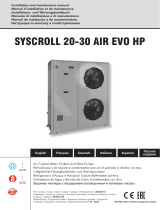
Fig. 1 Basic components in left hand unit
208766 | A003

2| Product description
Position Description
1. Compressor
2. Condenser coil
3. Evaporator coil
4. Filter drier with sight glas
5. Electronic expansion valve
6. Drip-tray with drain
7. Water seal
8. Cable grommet for external cabling
9. El. cabinet
10. Frequency converter
11. Pressure/hot gas switches
12. Measuring points refrigerant system high/low
2.2 Electrical cabinet
5
4
3
2
1
6
7
8
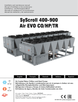
Fig. 2 Electrical cabinet
Position Description
1. Terminal block, mains supply
2. Circuit breaker (MCB) oil heater
3. Relays
4. Terminal block, internal/external connections
5. Frequency converter
6. DC choke
208766 | A003

Installing the unit | 3
Position Description
7. 24V transformer
8. LCD display
3 Installing the unit
3.1 Installation
Fig. 3 Installation, left hand unit
Position Description
Supply
Exhaust
Outdoor
Extract
1. VAV pressure transmitter supply air
(accessories)
2. VAV pressure transmitter extract air
(accessories)
3. Damper and motor exhaust air (accessories)
4. Damper and motor outside air (accessories)
5. Sensor supply air
6. Topvex SoftCooler SR
4 Refrigerant Control/Reporting
Topvex SoftCooler SR comes pre-filled with refrigerants and belongs to the group "Piece units containing more than
3kg refrigerants per circuit". Before commissioning shall always a control report in respect of the installation be estab-
lished by a cooling certified person. Leakage control with record keeping shall be done once per year. The installation of
the Topvex SoftCooler SR is only duty to report if the property/enterprise where the installation occurs, all together
after installation, has a total amount of refrigerants of 10 kg or more ("small Piece units" with refrigerants less than 3
kg, e.g. normal refrigerators/freezers does not includes). Reporting shall in occurring cases be done to major inspection
authority (normally the municipal environmental office).
Different regulations can be valid in different countries. Check with your local government.
208766 | A003

4|Function Description
5 Function Description
RC
RM
HE
EV
CO
FC
HPS
CPR
EV
CO
FC
HPS
CPR
Fig. 4 Left hand unit
Position Description
EF Extract air fan
SF Supply air fan
SS Temp. sensor supply air
OS Temp. sensor outdoor air
ETS Temp. sensor extract air
UC Control unit
RC Rotor control
RM Rotor motor
HE Exchanger
DO Damper outdoor air (accessory)
DEH Damper exhaust air (accessory)
FC Frequency converter
CPR Compressor
EV Evaporator
CO Condenser
HPS Condenser pressure sensor
OT/ET Overheating/Max. temp switches
FGS/FGE Air filter pressure switches
5.1 General
Control unit (UC) senses the temperature via the extract temperature sensor (ETS) and then keep the set extract tem-
perature by sequence controlling the compressor (CPR), heat exchanger (HE) and hot water- /electrical heater (HWL/H,
ELH). The temperature sensor in the supply air (SS) is min. and max. limiting the supply air temperature.
5.2 Power control
The compressor (CPR) are step-less controlled between, in the frequency converter (FC), set minimum and maximum
frequency.
5.3 Power limitation
The programmable controller is continuously sensing the condensing pressure via the high pressure sensor (HPS) and
gradually slows down the speed of the compressor (CPR), if the pressure exceeds the set limitation value. This is done
to avoid a high pressure alarm.
Note:
This instruction contains functions for the Topvex SoftCooler SR, for a complete description of functions see
" SR 09,11, TR 09-15 Installation instruction".
208766 | A003

Cooling flow chart | 5
6 Cooling flow chart
6.1 The cooling function
A
B
A
Extract air
B
Supply air
CRP Compressor
CCH Crank case heater
DT Drop tray
EV Evaporator
FD Filter drier
FC Frequency converter
HGS Hot gas switch
HPS Pressure sensor
CO Condenser coil
PSH Pressure switch, high
PSL Pressure switch, low
SG Sight glass
SR Pressure regulator
VD Vibration dampers
EXV Expansion valve
High and low manometer connections
208766 | A003

6| Cooling flow chart
The refrigerant is circulated in a completely closed system in the following order: Evaporator, Compressor, Condenser,
and last expansion valve. The compressor keeps a low pressure in the evaporator, the refrigerants boiling point is there-
by lowered and the incoming refrigerants from the expansion valve is vaporized (boiling) with absorption of heat as a
result. The heat is taken from the supply air when passing the evaporator - supply air temperature is lowered. After a
pressure increase in the compressor the refrigerant gas passing the condenser were the gas, thanks to the high pres-
sure and thereby a high boiling point, is transformed into fluid through condensation and thereby heat emission. The
heat is submitted to the exhaust air that passing the condenser. The heat has accordingly been transferred from supply
air to exhaust air. After leaving the condenser in liquid state the refrigerant passes the expansion valve who controls
the amount of refrigerants to the evaporator and thereby the cycle is completed.
6.2 Components and function
6.2.1 Compressor
The compressor in Topvex Soft Cooler is a high-efficiency, variable speed scroll compressor. It is designed especially for
speed control and can not run without frequency converter. Speed and by that cooling capacity is regulated by changing
the operating frequency, the maximum working range of the compressor is no less than 20 to 120 rps (revolutions per
second). In the smaller unit sizes the maximum frequency is limited via a setting in the frequency converter. Controlling
of the compressor is completely automatic according to the need of the premises and the signal comes via the control
unit to the frequency converter.
6.2.2 Frequency converter (FC)
The compressors frequency converter is located in the electrical cabinet. The programmable controller receives a con-
trol signal (0-10 V DC) corresponding to the current cooling load from the control unit and then, via frequency convert-
er, regulates the compressors speed according to the actual cooling load. The programmable controller has also a high
pressure sensor (HPS) (4-20 mA) connected. This sensor continuously measuring the pressure in the cooling system. If
the pressure exceeds the set value in the programmable controller the output frequency is reduced and thereby the
compressors speed will be reduced so that the pressure will not rise to the level were the high pressure switch (PSH)
on the high pressure side will trigger. The compressor is protected from fast start and stops by an restart delay function
(3 minutes) in the programmable controller.
6.2.2.1 Integrated control, quick guide
FLSTDmCOMM is the CAREL solution for the management of a BLDC compressor via Power+ inverter.
The FLSTDmCOMM software installed on the PCOOEM+ programmable board features:
• Easy-to-use add-on to manage BLDC compressor by Power+ inverter via an analogue signal (0-5V/0-10V) or con-
trolled via Modbus serial communication
• Full control of compressor working conditions, tested and approved by compressor manufacturers
• Use of electronic expansion valve manage via EVD EVO on-board (unipolar valve)
• No need of user interface (pGD1) when connecting to a BMS Modbus
• Energy saving and consequently cost savings, by integrated unit
• Improvement in system management, managed using a semi-graphic user interface (pGD1)
208766 | A003

Cooling flow chart | 7
6.2.2.1.1User interface
•Bell symbol
Display the list of active alarms
•Prg
Enter the main menu tree
•Esc
Return to the previous screen
•Up arrow
Scroll a list upwards or increase the value
shown on the display
•Enter arrow
Enter the selected submenu or confirm the set
value
•Down arrow
Scroll a list down wards or decrease the value
shown on the display
6.2.2.1.2PGD1 Menu
From this mask you have access to the specific menu
dedicated to the Power+ inverter parameters.
Submenu masks are marked as follows:
• Configuration masks, with Pa01, Pa02, etc
• Regulation masks, with Pb01, Pb02, etc
• Custom configuration masks, with Pc01, Pc02, etc
From this mask you have access to the specific menu
dedicated to the EVD Evo Parameters.
Submenu masks are marked as follows:
• Configuration masks, with Ea01, Ea02, etc
• Regulation masks, with Eb01, Eb02, etc
• Manual cmd masks, with Ec01, Ec02, etc
From this mask you have access to the manual control of
compressor and EVD valve for servicing; masks are indexes as
Ma01 and Ma02.
From this mask you have access to the masks dedicated to the
other parameters; all these masks are marked with Ot01, Ot02,
etc.
From this mask you have access to the specific masks
dedicated to the defrost option parameters; all these masks
are marked with Df01, Df02, etc.
From this mask you have access to the specific masks
dedicated to the BLDC compressor parameters; all these masks
are marked with Co01, Co02, etc.
6.2.2.1.3Pa Menu: Power+ configuration
Reserved to Power + inverter configuration (e.g. "Compressor model"): generally there is no need to access to these
masks for the purpose of this application program as all necessary setting has already been configured at the origin.
208766 | A003

8| Cooling flow chart
This mask permits to select the compressor model controlled by Power+.
Every change must be followed by the “Set defaults” command to send the new
parameters values to the Power +.
For specific particular purpose, it is possible to save as “Custom” a special configuration
made by changing some parameter of the characteristic ones of a compressor model.
N.B.: the modification of the Power+ parameters has to be done by qualified personnel
only, because it can result in a damage either for the compressor than for the Power+.
This masks allows to set the delay time before giving the alarm “Power+ offline” due to
the absence of answers to the enquire of the PCOOEM+; the last row parameter permits
to overcome ghost alarms at power up, e.g. when the “Safety Torque Off” digital input of
the Power+ is used.
This mask permits to select the measuring unit of the speed shown in the mask “Sn11”
6.2.2.1.4Pb Menu: Power+ regulation
Reserved to Power + inverter regulation: there is no need to access to these masks for the purpose of this application
program as all necessary setting has already been configured at the origin.
The parameters show the frequency limits of Power+ referred to the selected
compressor.
It may be necessary to avoid particular frequencies in some systems due to mechanical
resonance problems. Using the following parameters it is possible to fix the limits of the
frequency area to be avoided for the frequency set point.
Switching frequency and its optional setting.
This masks defines the stopping mode with no deceleration ramp control, the disabling of
the reverse speed (compressor damage!) and of the flying start (not possible with
compressor).
The parameters of this mask permit the configuration of the output relay and of the PTC
reading input (not used) with the relevant alarm delay time.
6.2.2.1.5Pc Menu: Power+ custom
Reserved to Power + inverter regulation: there is no need to access to these masks for the purpose of this application
program as all necessary setting has already been configured at the origin.
208766 | A003

Cooling flow chart | 9
Configuration of BLDC motor type.
The base frequency is the frequency at which the maximum voltage is applied. The base
voltage is the maximum voltage applied to the motor.
The rated current is the current at full load. The power factor is not used in the BLDC
motor type. Maximum current is set at 100%.
Frequency step values of the start-up speed profile management: the function is disabled
as the starting up is fully controlled by FLSTDmCOMM software installed on the PCOOEM
+.
Acceleration values of the start-up speed profile management: the function is disabled as
the starting up is fully controlled by FLSTDmCOMM software installed on the PCOOEM+.
Maintaining periods of speed prefixed values in the start-up speed profile management:
the function is disabled as the starting up is fully controlled by FLSTDmCOMM software
installed on the PCOOEM+.
Other parameters of the start-up speed profile management: the function is disabled as
the starting up is fully controlled by FLSTDmCOMM software installed on the PCOOEM+.
Maximum value of deceleration ramp for the compressor in use.
These parameters optimize the initial start-up phase of the motor by adapting the V/f
feature on the basis of the particular application, in order to improve performance at low
speeds.
Parameters related to the motor electrical data.
Other parameters related to the motor electrical data (mathematical model of the
motor).
PI regulation parameters to follow and maintain the specified speed value.
208766 | A003

10 | Cooling flow chart
These parameters optimize the initial start-up phase of the motor and the relative
estimate of the position and the motor speed.
Special function settings to perform the direct writing of a specified parameter new value
into Power+.
6.2.3 Power controlling
Control unit in the air handling unit gives a demand signal (Cooling (SEQ-C), 0-10V DC) in proportion to the current
cooling demand in the extract air (or room). The signal is, via a relay (R1), connected to an analog input in the program-
mable controller. When the signal is connected (R1) actuates and the compressor starts and the speed is then con-
trolled according to the demand signal between min. frequency (20 rps) and max. frequency (depends on unit size but
still max. 120 rps).
6.2.4 Compressor protection
The compressor is protected by the following:
• Motor protection in the frequency converter (FC)
• High pressure switch in the high pressure side (PSH)
• Low pressure switch on the low pressure side (PSL)
• Hot gas thermostat on the hot gas tube (HGS)
• If any of the above protections is triggered control unit will show Malfunction cooling (SEQ-C). Manual ac-
knowledgment and reset must be done before the compressor can start again.
6.2.5 Refrigerant
The refrigerant is of type R410 A, the system comes pre-filled and tested at the factory. On top of the Topvex Soft-
Cooler are the high- and low pressure side measuring points (tappings). Concerning the control and reporting of the re-
frigerant installation, see chapter 4.
6.2.6 Condenser/Evaporator
The condenser and evaporator coil is made of copper tubes with aluminium fins.
6.2.7 Drip tray
The drip tray is located under the evaporator/brine coil and collects the water condense that periodically occur during
the cooling operation. The drip tray is made of stainless steel and has a 32 mm connection for connecting the drain pipe.
The drip tray has an electrical heater to prevent the water condense from freezing.
208766 | A003

Maintenance |11
7 Maintenance
Caution
Maintenance of the Topvex SoftCooler is of great importance for the whole installations environmental
influence, operating economy, durability, security and functions.
Read the Warnings chapter 1 and Refrigerant Control/Reporting chapter 4 before doing any work on the
SoftCooler unit.
Maintenance should be carried out two times a year, apart from general cleaning the following should be done:
1. Leakage control with registration (Legal requirements: at least 1 time a year)
Different regulations can be valid in different countries. Check with your local government.
2. General control.
When unit is running listen for abnormal sounds and vibrations. Inspect occurrence of oil leakage (can be a symptom
on refrigerant leakage). Inspect occurrence of corrosion, fretting damages, loosen pipe suspensions.
3. Control of the cooling coil (evaporator coil) and condenser coil.
After a long time of use the coils can obtain a deposit that obstructs the heat transfer and airflow. Vacuum clean the
coils carefully from the dirty side.
4. Control of the drip tray.
After a long time of use the drip tray and the drain can obtain a deposit that obstructs the drain of the condensation
water. Clean the drip tray, drain, water seal and pipes from dirt and deposits.
5. Control of the air filter for the frequency converter.
The filter is located in the inspection door. After a long time of use the filter can be clogged so that the cooling airflow
decreases and thereby causes a to high temperature for the frequency converter which results in operational disturb-
ance. Loosen the filter from outside of the unit (snap locking of the cover), if the filter is dirty exchange it with a new
(filter mat G5).
208766 | A003

12 | Alarms
8 Alarms
When an alarm is activated a message is displayed, the corresponding LED comes on and where necessary the alarm
relay is activated.
The alarms can be divided into three categories:
• Serious unit alarms (these stop the compressor).
• Alarms that stop one or more functions of the system.
• Other alarms (signal only or “warnings”) that do not stop any function, but rather warn the user that certain thresh-
olds have been exceeded, for example.
To monitor active alarms simply press the bell symbol and the display will show the name (or names, if there is more
than one active alarm); to scroll the list, use the arrow up/down buttons.
To reset the alarms, display them and then press again. If the alarm condition no longer exists, the alarm is reset, other-
wise it will be shown again.
Note:
With automatic reset, the system restarts operating in as, however the alarm LED and the corresponding
warning string remain active until the bell symbol is pressed at least twice.
Table 1 Alarms
Alarm
code
Display description Reset Delay Alarm
relay
Action
AL01 Clock board fault or not connected Automatic Immediate Yes Just warning
signal
AL02 Extended memory error Automatic Immediate Yes Just warning
signal
AL03 Max discharge pressure Automatic Immediate Yes Off compressor
AL04 Min. suction pressure Automatic Immediate Yes Off compressor
AL05 Power+ offline Automatic 30 sec Yes Off compressor
208766 | A003

Alarms | 13
Alarms cont'd
Alarm
code
Display description Reset Delay Alarm
relay
Action
AL06
Alarms Power+ n°1
0. No fault
1. Overcurrent
2. Motor overload
3. Overvoltage
4. Undervoltage
5. Drive overT
6. Drive underT
7. Overcurrent HW
8. Motor overtemp.
9. Reserved
10. CPU error
11. Param. default
12. DC bus ripple
13. Data comms fault
14. Drive thermistor
15. Autotune fault
16. Drive disabled
17. Motor phase
18. Fan fault
19. Speed fault
20. PFC failure
21. -
22. PFC undervoltage
23. STO Surevey
24. STO Survey
...
99. Unexpected inverter stop
Manual Immediate Yes Off compressor
AL07 EVD Evo Probes fault or disconnected Automatic Immediate Yes Off compressor
AL08 EVD Evo Low SuperHeat Automatic Immediate Yes Just warning
signal
AL09 EVD Evo Low evaporation temperature (LOP) Automatic Immediate Yes Just warning
signal
AL10 EVD Evo High evaporation temperature (MOP) Automatic Immediate Yes Just warning
signal
AL11 EVD Evo Low suction temperature Automatic Immediate Yes Just warning
signal
AL12 Compressor start failure After 5 time
in 1 hour
became
10 sec Yes Off compressor
AL13 Operating limit alarm (forced compressor closing due
to exceeded operating limit)
Manual 60 sec Yes Off compressor
AL14 Delta Pressure < than minimum required for
lubrication
Automatic 60 sec Yes Off compressor
AL15 Discharge max.temp. Manual Immediate Yes Off compressor
AL16 Temperature Probe U1 faulty or disconnected Automatic 60 sec Yes Just warning
signal
AL17 Temperature Probe U2 faulty or disconnected Automatic 60 sec Yes Just warning
signal
AL18 Temperature Probe U3 faulty or disconnected Automatic 60 sec Yes Just warning
signal
AL19 Temperature Probe U4 faulty or disconnected Automatic 60 sec Yes Off compressor
208766 | A003

14 | Alarms
Alarms cont'd
Alarm
code
Display description Reset Delay Alarm
relay
Action
AL20 Pressure Probe U5 faulty or disconnected Automatic 60 sec Yes Off compressor
AL21 Pressure Probe U6 faulty or disconnected Automatic 60 sec Yes Off compressor
AL22 Pressure Probe U7 faulty or disconnected Automatic 60 sec Yes Off compressor
AL23 Defrost ended by max time duration Automatic Yes Lock defrost
AL24 BMS offline (bit unchanged) Automatic 20 se Yes Depends on
setting
AL25 Inverter model not compatible (Power+ only
allowed)
Automatic 60 sec Yes Off compressor
AL26 Start fail due to high DeltaP Automatic 300 sec Yes Off compressor
208766 | A003

208766 | A003

Topvex SoftCooler SR09, SR11Access control system · Operation and Maintenance Instructions · 208766 · en_GB · 04-09-2019 · A003
Systemair Sverige AB
Industrivägen 3
SE-739 30 Skinnskatteberg, Sweden
Phone +46 222 440 00
Fax +46 222 440 99
www.systemair.com
/