Badger Meter B280-737 User manual
- Category
- Measuring, testing & control
- Type
- User manual
This manual is also suitable for

Flow Monitor
B2800XP Explosion Proof Flow Monitor Standard
DSY-PM-00277-EN-03 (March 2017)
User Manual

CONTENTS
Scope of This Manual . . . . . . . . . . . . . . . . . . . . . . . . . . . . . . . . . . . . . . . . . . . . . . . . . . . . . . . . . . . . . . . . . . . 3
Unpacking and Inspection . . . . . . . . . . . . . . . . . . . . . . . . . . . . . . . . . . . . . . . . . . . . . . . . . . . . . . . . . . . . . . . 3
Safety . . . . . . . . . . . . . . . . . . . . . . . . . . . . . . . . . . . . . . . . . . . . . . . . . . . . . . . . . . . . . . . . . . . . . . . . . . . . . 3
Terminology and Symbols . . . . . . . . . . . . . . . . . . . . . . . . . . . . . . . . . . . . . . . . . . . . . . . . . . . . . . . . . . . . . 3
Considerations . . . . . . . . . . . . . . . . . . . . . . . . . . . . . . . . . . . . . . . . . . . . . . . . . . . . . . . . . . . . . . . . . . . . 3
Introduction. . . . . . . . . . . . . . . . . . . . . . . . . . . . . . . . . . . . . . . . . . . . . . . . . . . . . . . . . . . . . . . . . . . . . . . . . 4
Explosion Proof Enclosure . . . . . . . . . . . . . . . . . . . . . . . . . . . . . . . . . . . . . . . . . . . . . . . . . . . . . . . . . . . . . . . . 4
Installation. . . . . . . . . . . . . . . . . . . . . . . . . . . . . . . . . . . . . . . . . . . . . . . . . . . . . . . . . . . . . . . . . . . . . . . . . . 5
Installation Kits . . . . . . . . . . . . . . . . . . . . . . . . . . . . . . . . . . . . . . . . . . . . . . . . . . . . . . . . . . . . . . . . . . . . . . . 6
Operating the Monitor . . . . . . . . . . . . . . . . . . . . . . . . . . . . . . . . . . . . . . . . . . . . . . . . . . . . . . . . . . . . . . . . . . 7
Buttons . . . . . . . . . . . . . . . . . . . . . . . . . . . . . . . . . . . . . . . . . . . . . . . . . . . . . . . . . . . . . . . . . . . . . . . . . 7
Modes. . . . . . . . . . . . . . . . . . . . . . . . . . . . . . . . . . . . . . . . . . . . . . . . . . . . . . . . . . . . . . . . . . . . . . . . . . 7
Programming . . . . . . . . . . . . . . . . . . . . . . . . . . . . . . . . . . . . . . . . . . . . . . . . . . . . . . . . . . . . . . . . . . . . . . . . 8
Programming Mode. . . . . . . . . . . . . . . . . . . . . . . . . . . . . . . . . . . . . . . . . . . . . . . . . . . . . . . . . . . . . . . . . 8
Run Mode . . . . . . . . . . . . . . . . . . . . . . . . . . . . . . . . . . . . . . . . . . . . . . . . . . . . . . . . . . . . . . . . . . . . . . . 9
Additional Scaling Parameters . . . . . . . . . . . . . . . . . . . . . . . . . . . . . . . . . . . . . . . . . . . . . . . . . . . . . . . . . . . . 10
Flow 4 mA Setting . . . . . . . . . . . . . . . . . . . . . . . . . . . . . . . . . . . . . . . . . . . . . . . . . . . . . . . . . . . . . . . . . 10
Flow 20 mA Setting . . . . . . . . . . . . . . . . . . . . . . . . . . . . . . . . . . . . . . . . . . . . . . . . . . . . . . . . . . . . . . . . 10
4…20 mA Calibration . . . . . . . . . . . . . . . . . . . . . . . . . . . . . . . . . . . . . . . . . . . . . . . . . . . . . . . . . . . . . . . 10
4…20 mA Test . . . . . . . . . . . . . . . . . . . . . . . . . . . . . . . . . . . . . . . . . . . . . . . . . . . . . . . . . . . . . . . . . . . 10
Additional Input Options . . . . . . . . . . . . . . . . . . . . . . . . . . . . . . . . . . . . . . . . . . . . . . . . . . . . . . . . . . . . . . . 11
Battery Replacement . . . . . . . . . . . . . . . . . . . . . . . . . . . . . . . . . . . . . . . . . . . . . . . . . . . . . . . . . . . . . . . . . . 11
Maintenance . . . . . . . . . . . . . . . . . . . . . . . . . . . . . . . . . . . . . . . . . . . . . . . . . . . . . . . . . . . . . . . . . . . . . . . 12
Troubleshooting Guide. . . . . . . . . . . . . . . . . . . . . . . . . . . . . . . . . . . . . . . . . . . . . . . . . . . . . . . . . . . . . . . . . 13
Replacement Parts. . . . . . . . . . . . . . . . . . . . . . . . . . . . . . . . . . . . . . . . . . . . . . . . . . . . . . . . . . . . . . . . . 13
Specications . . . . . . . . . . . . . . . . . . . . . . . . . . . . . . . . . . . . . . . . . . . . . . . . . . . . . . . . . . . . . . . . . . . . . . . 14
Dimensions . . . . . . . . . . . . . . . . . . . . . . . . . . . . . . . . . . . . . . . . . . . . . . . . . . . . . . . . . . . . . . . . . . . . . . . . 15
Part Number Information . . . . . . . . . . . . . . . . . . . . . . . . . . . . . . . . . . . . . . . . . . . . . . . . . . . . . . . . . . . . . . . 15
Flow Monitor, B2800XP Explosion Proof Flow Monitor Standard
Page ii March 2017

SCOPE OF THIS MANUAL
This manual is intended to help you get the B2800 flow monitor up and running quickly.
MPORTANTI
Read this manual carefully before attempting any installation or operation. Keep the manual accessible for future reference.
UNPACKING AND INSPECTION
Upon opening the shipping container, visually inspect the product and applicable accessories for any physical damage such
as scratches, loose or broken parts, or any other sign of damage that may have occurred during shipment.
OTE:N If damage is found, request an inspection by the carrier’s agent within 48 hours of delivery and file a claim with the
carrier. A claim for equipment damage in transit is the sole responsibility of the purchaser.
SAFETY
Terminology and Symbols
Indicates a hazardous situation, which, if not avoided, is estimated to be capable of causing death or
serious personal injury.
Indicates a hazardous situation, which, if not avoided, could result in severe personal injury or death.
Indicates a hazardous situation, which, if not avoided, is estimated to be capable of causing minor or
moderate personal injury or damage to property.
Considerations
The installation of the B2800 monitor must comply with all applicable federal, state, and local rules, regulations, and codes.
EXPLOSION HAZARD - SUBSTITUTION OF COMPONENTS MAY IMPAIR SUITABILITY FOR CLASS I, DIVISION 2.
AVERTISSMENT
RISQUE D’EXPLOSION - LA SUBSTITUTION DE COMPOSANTS PEUT RENDRE CEMATÉRIEL INACCCEPTABLE POUR LES
EMPLACEMENTS DE CLASSE I, DIVISION 2.
DO NOT CONNECT OR DISCONNECT EITHER POWER OR OUTPUTS UNLESS THE AREA IS KNOWN TO BE NON-
HAZARDOUS.
AVERTISSMENT
RISQUE D’EXPLOSION. NE PAS DÉBRANCHER TANT QUE LE CIRCUIT EST SOUSTENSION, À MOINS QU’LL NE S’AGISSE
D’UN EMPLACEMENT NON DANGEREUX.
MPORTANTI
Not following instructions properly may impair safety of equipment and/or personnel.
Scope of This Manual
Page 3 March 2017 DSY-PM-00277-EN-03

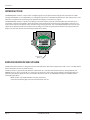
INTRODUCTION
The B2800XP flow monitor is a state-of-the-art digital signal processing flow monitor designed to provide the user with
exceptional flexibility at a very affordable price. Though designed for use with Blancett flow meters, this display can be used
with almost any flow meter producing a low amplitude AC output or contact closure signals.
The B2800XP flow monitor is capable of accepting a low level frequency input for calculating flow rate and total. These
calculations can then be displayed in the desired units of measurement. The monitor’s large eight digit by 0.50 inch (12.7
mm) numeric liquid crystal display makes extended range viewing practical. The second eight digit by 0.25 inch (6.35 mm)
alphanumeric display provides for selectable units viewing in run mode and prompts for variables in program mode. The
display can show rate, total or alternate between both rate and total.
Programming
Buttons
MENU ENTER
EXPLOSION PROOF ENCLOSURE
The EIH Instrument enclosure is designed to house instrumentation and control equipment as well as act as a conduit outlet
body in hazardous, abusive and wet locations.
The EIH enclosure is approved by Underwriters Laboratories Inc., Canadian Standards Association, Factory Mutual and
CENELEC for use in Class I, Groups B*, C** and D; Class II, Groups E, F and G; and Class II hazardous (classified) locations as
defined by the National Electrical Code and Canadian Electrical Code. It is also NEMA/UL/CSA Type 4 and IP66 rated for
watertight applications.
*With conduit seals installed within 18 inches of enclosure.
**Unsealed conduit lengths must not exceed five feet (152 cm).
Introduction
Page 4 March 2017 DSY-PM-00277-EN-03

INSTALLATION
ELECTRICAL POWER MUST BE TURNED OFF BEFORE AND DURING INSTALLATION AND MAINTENANCE.
1. EIH Instrument enclosures are furnished with 3/4 inch NPT oset through feed cast hubs for conduit entries. (Use Cooper
Crouse-Hinds RE21-SA to reduce to 1/2 inch hubs.)
2. Secure the enclosure to the conduit system. If the enclosure has mounting feet, select a mounting location that will
provide sucient strength and rigidity to support the enclosure as well as the enclosed device and wiring.
SELECT A MOUNTING LOCATION SO THAT THE ENCLOSURE WILL NOT BE SUBJECTED TO IMPACT BY HEAVY OBJECTS.
IMPACTS CAN DAMAGE ENCLOSED DEVICES OR GLASS LENS.
3. Install Cooper Crouse-Hinds EYS sealing ttings required by Section 501-5 and/or 502-5 of the National Electrical Code and
Section 18 of the Canadian Electrical Code or any other applicable local codes and when enclosure is installed in Class I
Group B hazardous locations. (For CSA Group C applications, unsealed conduit lengths must not exceed
ve feet or 152 cm.)
THE HAZARDOUS LOCATION INFORMATION SPECIFYING CLASS AND GROUP LISTING OF EACH INSTRUMENT
ENCLOSURE IS MARKED ON THE NAMEPLATE OF EACH ENCLOSURE.
ALL UNUSED CONDUIT OPENINGS MUST BE PLUGGED. PLUG UNUSED CONDUIT OPENINGS WITH COOPER CROUSE-
HINDS PLG2. PLUGS MUST BE A MINIMUM OF 1⁄8 INCH THICK AND ENGAGE A MINIMUM OF FIVE FULL THREADS.
4. Unthread instrument (and power side) covers and carefully set aside to prevent damage to the cover threads and glass
lens (when glass lens cover is used).
5. Pull wires into enclosure making certain they are long enough to make the required connections and to remove the
instrument or power supply if servicing is required. Install instrument and power supply, if applicable, and make all
electrical connections.
OTE:N When installing device, be sure to check instrument dimensions to avoid interference with clamping ring on glass
lens and the cover on standard units.
6. Test wiring for correctness by checking continuity and also check for unwanted grounds with insulator resistance tester.
Make sure test equipment being used will not damage instrument to be housed in the EIH Instrument enclosure.
7. Carefully re-thread cover to enclosure housing. Tighten cover until cover ange contacts body face.
USE CARE TO PREVENT DIRT, GRIT OR OTHER FOREIGN MATERIAL FROM LODGING ON THREADS. IF SUCH MATERIAL
SETTLES ON THREADS, CLEAN WITH KEROSENE OR STODDARD SOLVENT*, THEN RE-LUBRICATE WITH COOPER
CROUSE-HINDS TYPE STL THREAD LUBRICANT.
8. Tighten cover set screws to prevent cover from loosening under vibration.
* TO AVOID THE POSSIBILITY OF AN EXPLOSION, OXIDATION AND CORROSION, DO NOT USE GASOLINE OR SIMILAR
SOLVENT.
TO MAINTAIN THE EXPLOSION PROOF INTEGRITY OF THE ENCLOSURE WITH A SCREW IN A TAPPED MOUNTING PAD
HOLE, THERE MUST BE A MINIMUM OF 1⁄16 INCH OF MATERIAL BETWEEN THE DRILL POINT AND THE BACK WALL. IF
FOR ANY REASON A SCREW WILL NOT BE THREADED INTO THE DRILLED HOLE, A MINIMUM OF 1⁄8 INCH OF MATERIAL
MUST REMAIN BETWEEN THE DRILL POINT AND THE BACK WALL.
Installation
Page 5 March 2017 DSY-PM-00277-EN-03

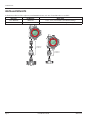
INSTALLATION KITS
To facilitate installation of the explosion proof B2800XP monitor, two sizes of installation kits are available.
Hub Size Kit Number Meter Sizes
1/2 in. NPT Hub B280-742 3/8 in., 1/2 in., 3/4 in. with 1/2 in. NPT End Fittings
1 in. NPT Hub B280-737 All Sizes with 1 in. NPT End Fittings and Larger
Installation Kit
P/N: B280-737
Installation Kit
P/N: B280-742
Installation Kits
Page 6 March 2017 DSY-PM-00277-EN-03

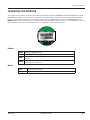
OPERATING THE MONITOR
The monitor has two modes of operation referred to as the RUN mode and the PROGRAM mode. Both the RUN mode and the
PROGRAM mode display screen enunciators confirm the state of the monitor. A quick glance at the lower left corner of the
LCD screen will confirm operating status. Normal operation will be in the RUN mode. To access the PROGRAM mode, press
MENU until the first programming screen is displayed. After programming the display with the necessary information, turn on
the lock out feature to prevent unauthorized access or changing the meter’s setup parameters.
MENU ENTER
Buttons
MENU Switches to PROGRAM mode
UP Scrolls forward through the parameter options and increments numeric variables
RIGHT
Scrolls backward through the parameter options and moves the active digit to
the right
ENTER
Saves programming information, advances to the next programming parameter,
and used in the reset process
Modes
RUN Normal operating mode
PROGRAM Used to program parameters in the display
Operating the Monitor
Page 7 March 2017 DSY-PM-00277-EN-03

PROGRAMMING
Each turbine flow meter is shipped with either a K-factor value or frequency data. If frequency data is provided, the data must
be converted to a K-factor before programming the monitor. K-factor information, when supplied, can usually be found on the
neck of the flow meter or stamped on the flow meter body. The K-factor represents the number of pulses per unit of volume.
The K-factor is needed to program the monitor readout.
Programming Mode
K Factor Units
Units
Pulse Output
IO/SETUP
METER
PUL/GAL PUL/FT3PUL/LTRPUL/M3
K FACTOR
GPM/GAL
LPM/LIT M3PH/M3
M3PD/M3
BPD/BBL
DSP
BOTH TOTAL RATE TEST
PULS ON PULS OFF
PASSWORD
RST PSWD
Enter Program Mode
Press MENU to enter the programming mode. The mode indicator changes from RUN to PROGRAM.
Select Meter Size
At the METER prompt, press UP or RIGHT to scroll to the bore size of your meter. Press ENTER to save and advance to the
K-factor Units parameter.
OTE:N The meter connection size and the bore size are different. For example, many of the one inch NPT turbines have bore
sizes that range from 3/8…1 in. Be sure to use the correct bore size or the meter will report incorrect flows and totals.
Enter The K-Factor Unit
Press UP or RIGHT to scroll to the K-factor unit of the meter. Enter the unit that the meter was calibrated in.
Example
If the meter was calibrated in US gallons, use PUL/GAL.
Press ENTER to save the K-factor unit and advance to the K FACTOR parameter.
OTE:N Unless otherwise specified, Blancett turbine flow meters are supplied with K-factors measured in pulses per gallon
(PUL/GAL) which will automatically convert to your desired units of measure.
Enter The Meter's K-Factor
OTE:N The K-factor supplied with the meter or calculated from calibration data is needed to set this parameter.
To change the K-factor value, press RIGHT to select the digit that you wish to change. Press UP to increment the digit until it
matches the meter’s K-factor. Repeat this process until all K-factor digits have been entered. Press ENTER to save the K-factor
and advance to RATE/TOTAL.
Programming
Page 8 March 2017 DSY-PM-00277-EN-03

Select the Units of Measure
The monitor is programmed with five common rate/total unit options. The monitor shows the rate/total unit that the display
is currently set for. If the current selection is correct, press ENTER once to advance to the DISPLAY FUNCTION parameter.
To change the unit, press UP or RIGHT to scroll to the correct rate unit. Press ENTER to save and advance to the DISPLAY
FUNCTION parameter.
Selection Rate Total
GPM/GAL Gallons per minute Gallons
LPM/LIT Liters per minute Liters
M3PH/M3 Cubic meters per hour Cubic meters
M3PD/M3 Cubic meters per day Cubic meters
BPD/BBL Oil barrels per day Oil barrels
Select the Display Function
The monitor displays RATE, TOTAL, alternates between BOTH rate and total or TEST. If the current selection is correct, press
ENTER to advance to the next parameter. To change to an alternate display mode, press UP or RIGHT to scroll to the correct
display mode and press ENTER to save and advance to the TOTALIZER PULSE OUTPUT parameter.
The TEST function acts like a frequency counter and displays the raw input frequency being supplied to the frequency input
terminals. This is very useful when troubleshooting flow problems.
Totalizer Pulse Output
The pulse output parameter can be enabled or disabled. When enabled this output generates 20 mS duration pulse for every
time the least significant digit of the totalizer increments. The amplitude of the pulse is dependent on the voltage level of the
supply connected to the pulse output and is limited to a maximum 30V DC. Press UP or RIGHT to scroll to ON or OFF. Press
ENTER to save and advance to the PASSWORD parameter.
Password
The PASSWORD setting restricts access to PROGRAM mode. Initially, the password is set to all zeros and any user can modify
the parameter settings in PROGRAM mode. To change the password, enter any four digit code. Press UP to increment the digit,
and RIGHT to advance to the next digit. Press ENTER to store the password and advance to RST PSWD. The new password is
now required to enter PROGRAM mode. With this password set, any user is able to reset the stored totals on the monitor.
Reset Password
The RST PSWD restricts resetting the totals on the monitor. The PASSWORD must also be set to restrict the total reset. Initially,
the password is set to all zeros and any user can reset the stored totals on the monitor. To change the password, enter any four
digit code. Press UP to increment the digit, and RIGHT to advance to the next digit. After entering all digits, press ENTER to
store the password and return to RUN mode. The reset password is now required to reset the totals on the monitor.
Run Mode
Reset Total
To reset the monitor total display, in RUN mode press MENU and ENTER simultaneously. If the RST PSWD has been set to
something other than the default, you must enter the new password before the monitor will reset. The monitor flashes
TOTAL RST and returns to RUN mode at the conclusion of the reset procedure.
Store Total
The current total can be manually stored in the monitor’s flash memory. Use this feature prior to replacing the battery. Press
and hold ENTER for 2 seconds. The display responds with a flashing TOTALSVD and then returns to RUN mode.
Automatic Store Total
The monitor is equipped with a store total feature that works automatically, saving the current total to flash memory. The
frequency of saves depends on the power supply option chosen.
Battery Powered: Once per hour and just before a low battery condition turns the unit o.
Loop Powered: Once every ten minutes.
Programming
Page 9 March 2017 DSY-PM-00277-EN-03

ADDITIONAL SCALING PARAMETERS
OTE:N The programming instructions below are only available for loop powered units. Battery powered units do not include
these programming parameters.
Flow 4 mA Setting
Zero is the default flow rate at the 4 mA setting. If the current selection is correct, press ENTER to advance to the Flow 20 mA
parameter. To change the setting, press UP to increment the flashing digit and press RIGHT to move to the next digit. Press
ENTER to save and advance to the Flow 20 mA parameter.
Flow 20 mA Setting
The turbine meter’s maximum flow rate is the default value for the 20 mA setting. If the current selection is correct, press
ENTER to advance to the 4…20 mA Calibration parameter. To change the setting, press UP to increment the flashing digit and
press RIGHT to move to the next digit. Press ENTER to save and advance to the 4…20 mA Calibration parameter.
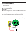
4…20 mA Calibration
The 4…20 mA Calibration parameter is the fine adjustment of the 4…20 mA output. The 4 mA setting is typically between
35…50. To set the 4 mA value, connect an ammeter in series with the loop power supply. At the 4MA OUT prompt, press UP to
increment and RIGHT to decrement the 4 mA value to until a steady 4 mA reading is reached on the ammeter. Press ENTER to
lock in this value and advance to 20MA OUT. The 20 mA adjustment is performed using the same procedure as the
4 mA adjustment.
4…20 mA Test
The monitor contains a diagnostic routine that allows the simulation of mA values between 4…20 to check output tracking.
At the 4-20TEST prompt press UP to increment the simulated mA output or RIGHT to decrement the value in increments of
1 mA. The ammeter should track the simulated mA output. If a 4…20 mA test in not necessary, press ENTER once to escape
the testing at any time.
Pulse Out Freq. In4-20 mA
+
-
+
-
+
-
Mag
Input
Pulse
Inuput
TB2 Reset
10…30V DC
1…5V DC
10A MAX
FUSED
400mA
FUSED
CAT III
1000V
HOLD MIN MAX REL
Hz % ms RANGE
AutoHOLD FAST MIN MX LOGGING YES
CANCEL SAVE NO
SETUP
µA
mA
A
W
V
TEMPERATURE
COM
OFF
nS
W
VIEW MEM
CLEAR MEM
V
dB
mV
dB
ac+dc
V
ac+dc
A
mA
mV
ac+dc
mA
A
µA
ac+dc
µA
°C
°F
MEM
MANUAL
%
DC
m
A
0 0
Additional Scaling Parameters
Page 10 March 2017 DSY-PM-00277-EN-03

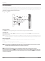
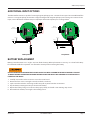
ADDITIONAL INPUT OPTIONS
The Blancett flow monitor is capable of receiving magnetic pickup input or a contact closure input. Since most Blancett flow
meters use a magnetic pickup, the monitor is shipped configured for magnetic pickup input. To change to a contact closure
input, remove JP2 from the bottom two pins and jumper them to the top two pins. See image below.
D
1.5 VOLTS
CAUTION DO NOT CONNECT IMPROPERLY
CHANGE OR DISPOSE OF IN FIRE. BATTERY
MAY EXPLODE OR LEAK. MADE IN U.S.A.
ALKALINE BATTERY
Pulse Out Freq. In4-20 mA
+
-
+
-
+
-
External
Totalizer Reset
10k
30V DC (Max)
20 mS Pulse
N/C N/C
Mag
Input
Pulse
Inuput
TB2 Reset
Pulse Out Freq. In4-20 mA
+
-
+
-
+
-
External
Totalizer Reset
10k
30V DC (Max)
20 mS Pulse
Mag
Input
Pulse
Inuput
TB2 Reset
10…30V DC
1…5V DC
250 Typ
O
MAX
=
(Loop Supply Voltage - 5)
0.02
Battery Power Loop Power
BATTERY REPLACEMENT
Battery powered monitors use a single 1.5V, D size alkaline battery. When replacement is necessary, use a clean fresh battery
for continued trouble-free operation. Save the total to memory before removing the battery.
DO NOT OPEN EXPLOSION PROOF ENCLOSURE UNLESS THE AREA IS KNOWN TO BE FREE OF HAZARDS. FAILURE
TO MAKE THE AREA SAFE BEFORE OPENING THE ENCLOSURE CAN RESULT IN A HAZARDOUS SITUATION WITH A
POTENTIAL FOR INJURY.
1. Carefully unscrew the enclosure cover to access the circuit board.
2. Remove the four screws securing the circuit board to the enclosure.
3. Lay the circuit board to the side being careful not to pull any wires from their connections.
4. Clip the battery retaining wire/strap and remove the battery.
5. Replace the battery, being sure to observe the proper polarity and install a new retaining strap or wire.
6. Reassemble the monitor, reversing the disassembly process.
Additional Input Options
Page 11 March 2017 DSY-PM-00277-EN-03

MAINTENANCE
ALWAYS DISCONNECT PRIMARY POWER SOURCE BEFORE OPENING ENCLOSURE FOR INSPECTION OR SERVICE.
1. Create a schedule for maintenance determined by the environment and frequency of use. Inspect the monitor at least
once a year.
2. Perform visual, electrical and mechanical checks on all components on a regular basis.
a. Visually check for undue heating evidenced by discoloration of wires or other components, damaged or worn parts, or
leakage evidenced by water or corrosion in the interior.
b. Electrically check to make sure that all connections are clean and tight, and that the device is operating correctly.
Maintenance
Page 12 March 2017 DSY-PM-00277-EN-03

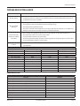
TROUBLESHOOTING GUIDE
Issue Remedy
No LCD display
• Battery Powered Version: Check battery voltage. Should be 1.5V DC. Replace if low or bad.
• Loop Powered Version: Check for current flow in the loop. Check polarity of the current loop
connections for proper orientation.
No rate or total
displayed
• Check connection from meter pickup to display input terminals.
• Check turbine meter rotor for debris. Rotor should spin freely.
• Check programming of flow monitor.
• Check to see that the minimum flow rate is being met for the current meter in use. Otherwise,
the flow meter will not accurately send pulses to the flow monitor.
Flow rate display
interprets reading
constantly
• This is usually an indication of external noise. Keep all AC wires separate from DC wires.
• Check for large motors close to the meter pickup.
• Check for radio antenna in close proximity.
• Try disconnecting the pickup from the monitor pig tail. This should stop the noise. If not, then
try reorientating the meter to a new location.
Flow rate indicator
bounces
• This usually indicates a weak signal. Replace pickup and/or check all connections.
• Check K-factor.
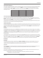
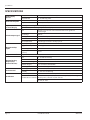
Default K-Factor Values
Meter Size Default K-Factor Lower Limit Upper Limit
3⁄8 in. (9.53 mm) 20,000 16,000 24,000
1/2 in. (12.7 mm) 13,000 10,400 15,600
3/4 in. (19.05 mm) 2750 2200 3300
7⁄8 in. (22.23 mm) 2686 2148 3223
1 in. (25.4 mm) 870.0 686.0 1044
1-1/2 in. (38.1 mm) 330.0 264.0 396.0
2 in. (50.8 mm) 52.0 41.6 62.0
3 in. (76.2 mm) 57.0 45.6 68.0
4 in. (101.6 mm) 29.0 23.2 35.0
6 in. (152.4 mm) 7.0 5.6 8.0
8 in. (203.2 mm) 3.0 2.4 4.0
10 in. (254 mm) 1.6 1.3 2.0
Replacement Parts
Component Part Number
Enclosure B280635
Battery B280601
Battery Holder B280634
Battery Tie Wrap B228036
Cap Plug 3/8 inch B118236
Desiccant Pouch B220141
Pickup Cable B222-121
Battery Mount Plate B280618
Adapter Bridge Plate B280677
Hex Standoffs B280667
Meter Mount Kit - For 1 inch Hub B280-737
Meter Mount Kit - For 1/2 inch Hub B280-742
Troubleshooting Guide
Page 13 March 2017 DSY-PM-00277-EN-03

SPECIFICATIONS
Power Supply
Options
Battery Powered One D size, 1.5V alkaline battery
Loop Powered 4…20 mA loop power
Power Consumption
Battery Powered Less than 1 mA @ 1.5V DC
Loop Powered 25 mA (maximum)
Alphanumeric Rate
and Total Display
Eight digit, 0.5 inch high numeric display
Eight character, 0.25 inch high alphanumeric display
Pulsed Output Signal
Type
Outputs one pulse for each increment of the least significant
totalizer digit
Max Voltage 30V DC
Pulse Type Opto-Isolated open collector transistor
Pulse Width ON State 20 mS / maximum pulse rate 20 Hz
Current (ON State) 0.9V drop @ 5.0 mA or 0.7V drop @ 0.1 A
Magnetic Pickup
Inputs
Frequency Range 0…3500 Hz
Trigger Sensitivity 30 mV p-p
Over Voltage Protected ±30V DC
Frequency Measurement
Accuracy
±0.1%
Temperature Drift 50 ppm / °C maximum
Optional Analog
Output (Loop
Powered Version)
Type 4…20 mA current loop
Resolution 1:4000
Transient Over Voltages Category 3, in accordance with IEC664
Pollution Degree 2, in accordance with IEC664
Mounting Classification NEMA/UL/CSA Type 4 (IP66)
Environmental
Operating Temperature –22…158° F (–30…70° C)
Humidity 0…90% non-condensing
Certification
CSA Ordinary Locations C22.2 No. 1010-1 for Canada; ANSI/ISA S82.02 for US
CSA Hazardous Locations
Class I, Div 1 Groups B,C, D; Class II, Div 1 Groups E, F, G; Class III; Type
4X; T6 @ 70° F; C22.2 No. 30; C22.2 No. 25
UL 698, UL 1203
Specications
Page 14 March 2017 DSY-PM-00277-EN-03

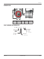
DIMENSIONS
MENU ENTER
B
D
A
C
E
¾ NPT
A B C D E
5.1 in.
(19.31 mm)
5.25 in.
(19.87 mm)
2.6 in.
(9.84 mm)
5/16 in.
(1.19 mm)
4.51 in.
(17.07 mm)
PART NUMBER INFORMATION
Program Level
S -
B 28 S X X - X X
Power Option
B - Battery
L - Loop
Mounting Style
X - Explosion proof
Units of Measure
AB - Gallons
ED - Barrels
HB - Liters
ID - Cubic Meters
Dimensions
Page 15 March 2017 DSY-PM-00277-EN-03

www.badgermeter.com
BLANCETT is a registered trademark of Badger Meter, Inc. Other trademarks appearing in this document are the property of their respective entities. Due to continuous research,
product improvements and enhancements, Badger Meter reserves the right to change product or system specications without notice, except to the extent an outstanding
contractual obligation exists. © 2017 Badger Meter, Inc. All rights reserved.
Control. Manage. Optimize.
Flow Monitor, B2800XP Explosion Proof Flow Monitor Standard
The Americas | Badger Meter | 4545 West Brown Deer Rd | PO Box 245036 | Milwaukee, WI 53224-9536 | 800-876-3837 | 414-355-0400
México | Badger Meter de las Americas, S.A. de C.V. | Pedro Luis Ogazón N°32 | Esq. Angelina N°24 | Colonia Guadalupe Inn | CP 01050 | México, DF | México | +52-55-5662-0882
Europe, Eastern Europe Branch Oce (for Poland, Latvia, Lithuania, Estonia, Ukraine, Belarus) | Badger Meter Europe | ul. Korfantego 6 | 44-193 Knurów | Poland | +48-32-236-8787
Europe, Middle East and Africa | Badger Meter Europa GmbH | Nurtinger Str 76 | 72639 Neuen | Germany | +49-7025-9208-0
Europe, Middle East Branch Oce | Badger Meter Europe | PO Box 341442 | Dubai Silicon Oasis, Head Quarter Building, Wing C, Oce #C209 | Dubai / UAE | +971-4-371 2503
Slovakia | Badger Meter Slovakia s.r.o. | Racianska 109/B | 831 02 Bratislava, Slovakia | +421-2-44 63 83 01
Asia Pacic | Badger Meter | 80 Marine Parade Rd | 21-06 Parkway Parade | Singapore 449269 | +65-63464836
China | Badger Meter | 7-1202 | 99 Hangzhong Road | Minhang District | Shanghai | China 201101 | +86-21-5763 5412
Switzerland | Badger Meter Swiss AG | Mittelholzerstrasse 8 | 3006 Bern | Switzerland | +41-31-932 01 11 Legacy Document Number: 02-DSY-PM-00114
-
 1
1
-
 2
2
-
 3
3
-
 4
4
-
 5
5
-
 6
6
-
 7
7
-
 8
8
-
 9
9
-
 10
10
-
 11
11
-
 12
12
-
 13
13
-
 14
14
-
 15
15
-
 16
16


Badger Meter B280-737 User manual
- Category
- Measuring, testing & control
- Type
- User manual
- This manual is also suitable for
Ask a question and I''ll find the answer in the document
Finding information in a document is now easier with AI
Related papers
-
 Badger Meter Blancett B2800 User manual
-
 Badger Meter Blancett B2800 Standard User manual
-
 Badger Meter Hedland EZ-View Quick Manual
-
 Badger Meter HR-RED User manual
-
 Badger Meter ER-500 Programming Manual
-
Badger Meter E-Series User manual
-
 Badger Meter Impeller Data Industrial 3050 Series User manual
-
 Badger Meter BadgerTouch HREBT User manual
-
 Badger Meter Register ILR 750 Programming Manual
-
 Badger Meter Recordall Disc Series Installation guide


Other documents
-
Z.Vex Fuzzolo User manual
-
Omega FTB790 Owner's manual
-
GPI 01N31GM Owner's manual
-
Eaton IF 1179 - EIH/EIHT Owner's manual
-
Badger Basket WT-2 User manual
-
-
-
Omega FTB-1400-MD/RD/SD-A Owner's manual
-
-
Dwyer Series TTMS User manual