Remote Automation Solutions GOST Flow Calculation (FB103) User guide
- Type
- User guide

Remote Automation Solutions
GOST Flow Calculation Program
(For the FloBoss 103)
User Manual
(QER 05Q039)
D301834X012
Form A6195
March 2009

GOST Flow Calculation Program User Manual
ii Rev. Mar-09
Revision Tracking Sheet
March 2009
This manual may be revised periodically to incorporate new or updated information. The revision date of each
page appears at the bottom of the page opposite the page number. A change in revision date to any page also
changes the date of the manual that appears on the front cover. Listed below is the revision date of each page (if
applicable):
Page Revision
All pages Mar-09
All pages Oct-08
All pages Jul-06
All pages Sep-05
NOTICE
“Remote Automation Solutions (“RAS”), division of Emerson Process Management shall not be liable for technical or editorial errors in this
manual or omissions from this manual. RAS MAKES NO WARRANTIES, EXPRESSED OR IMPLIED, INCLUDING THE IMPLIED
WARRANTIES OF MERCHANTABILITY AND FITNESS FOR A PARTICULAR PURPOSE WITH RESPECT TO THIS MANUAL AND, IN NO
EVENT SHALL RAS BE LIABLE FOR ANY INCIDENTAL, PUNITIVE, SPECIAL OR CONSEQUENTIAL DAMAGES INCLUDING, BUT NOT
LIMITED TO, LOSS OF PRODUCTION, LOSS OF PROFITS, LOSS OF REVENUE OR USE AND COSTS INCURRED INCLUDING
WITHOUT LIMITATION FOR CAPITAL, FUEL AND POWER, AND CLAIMS OF THIRD PARTIES.
Bristol, Inc., Bristol Canada, BBI SA de CV and Emerson Process Management Ltd, Remote Automation Solutions division (UK), are wholly
owned subsidiaries of Emerson Electric Co. doing business as Remote Automation Solutions (“RAS”), a division of Emerson Process
Management. FloBoss, ROCLINK, Bristol, Bristol Babcock, ControlWave, TeleFlow and Helicoid are trademarks of RAS. AMS, PlantWeb and
the PlantWeb logo are marks of Emerson Electric Co. The Emerson logo is a trademark and service mark of the Emerson Electric Co. All
other trademarks are property of their respective owners.
The contents of this publication are presented for informational purposes only. While every effort has been made to ensure informational
accuracy, they are not to be construed as warranties or guarantees, express or implied, regarding the products or services described herein or
their use or applicability. RAS reserves the right to modify or improve the designs or specifications of such products at any time without notice.
All sales are governed by RAS’ terms and conditions which are available upon request.
RAS does not assume responsibility for the selection, use or maintenance of any product. Responsibility for proper selection, use and
maintenance of any RAS product remains solely with the purchaser and end-user.”
© 2005-2009 Remote Automation Solutions, division of Emerson Process Management. All rights reserved.

GOST Flow Calculation Program User Manual
Rev. Mar-09 iii
Contents
Page
1 INTRODUCTION 1
1.1 Scope and Organization........................................................................................................ 1
1.2 Product Overview .................................................................................................................. 1
1.3 Program Requirements ......................................................................................................... 1
2 INSTALLATION 3
2.1 Downloading the GOST Flow Program ................................................................................. 3
3 CONFIGURATION 7
3.1 Device Information Screen .................................................................................................... 8
3.2 Meter Setup Screen .............................................................................................................. 9
3.2.1 Meter Setup Screen – General Tab ......................................................................... 10
3.2.2 Meter Setup Screen – Inputs Tab ............................................................................ 11
3.2.3 Meter Setup Screen – Advanced Tab ..................................................................... 12
3.3 History Setup Screen .......................................................................................................... 13
3.4 GOST Flow Data Screen .................................................................................................... 15
3.4.1 GOST Flow Data Screen – Setup Tab .................................................................... 16
3.4.2 GOST Flow Data Screen – Calculated Results Tab ............................................... 19
3.5 GOST Flows and Accums Screen ...................................................................................... 21
3.6 Saving the Configuration ..................................................................................................... 23
4 REFERENCE 25
4.1 GOST Flow Task Alarm List ............................................................................................... 25
4.2 GOST Flow Task Limits of Use ........................................................................................... 25
4.3 Point Type 22: GOST Flow User Data ................................................................................ 26
4.4 Point Type 23: Mass Calculations ....................................................................................... 29

GOST Flow Calculation Program User Manual
iv Rev. Mar-09
[This page is intentionally left blank.]

GOST Flow Calculation Program User Manual
Rev. Mar-09 1
1 INTRODUCTION
1.1 Scope and Organization
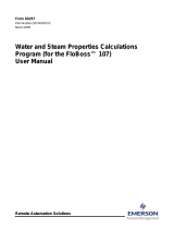
This document serves as the user manual for the GOST Flow Calculation Program (QER 05Q039),
which is intended for use in a FloBoss™ 103. This manual describes how to download and configure
this program (referred to as the “GOST Flow program” or “the program” throughout the rest of this
manual). You access and configure this program using ROCLINK 800 Configuration Software
(version 1.83 or greater) loaded on an IBM
®
-compatible personal computer (PC) running Windows
2000 (with Service Pack 2), Windows XP, or Windows Vista.
The sections in this manual provide information in a sequence appropriate for first-time users. Once you
become familiar with the procedures and the software running in a FloBoss 103, the manual becomes a
reference tool.
This manual has the following major sections:
Section 1 – Introduction
Section 2 – Installation
Section 3 – Configuration
Section 4 – Reference
This manual assumes that you are familiar with the FloBoss unit and its configuration. For more
information, refer to the FloBoss 103 and 104 Flow Managers Instruction Manual (Form A6114) or the
ROCLINK 800 Configuration Software User Manual (Form A6121).
1.2 Product Overview
The GOST Flow Calculation program allows a FloBoss 103 to calculate volumetric and mass flow rates,
integrate volumes and masses, and create and store historical values using the GOST 8.563-97 standard
or GOST 8.586-05 standard. This program replaces the AGA3 flow calculation. It uses AGA structures
where possible and provides two program-specific screens for entering and viewing additional program-
specific parameters.
With the program installed, the FloBoss 103 reads flow inputs (differential pressure, temperature, and
static pressure) once every second. It also performs a GOST 8.563 or GOST 8.586-05 instantaneous
flow calculation each second, followed by flow integration. The GOST flow calculation provides an
instantaneous volumetric flow rate (that is adjusted to contract pressure and temperature) and mass flow
rate. (Flow calculations and equations are detailed in GOST 8.563.1, 8.563.2, 8.586.1 and 8.586.2.) You
configure and view the program using three ROCLINK 800 screens (Device Information, Meter Setup,
and History Setup) and two program-specific screens (GOST Flow Data and GOST Flows & Accums).
1.3 Program Requirements
You download the GOST Flow Calculation program to—and then run it from—the Flash and RAM
memory on the FloBoss 103. The GOST Flow Calculations program is compatible only with firmware
version 2.14 (or greater) of the FloBoss 103. Download and configure the program using the ROCLINK
800 Configuration software (version 1.83 or greater).

GOST Flow Calculation Program User Manual
2 Rev. Mar-09
The downloadable program is:
File Name Unit Task Code Data UDP
Gostflow_v2.20.bin FloBoss 103 User 1 790000 46C000 22, 23
Note: You must connect a PC to the FloBoss unit’s LOI port before starting the download.
For information on viewing the memory allocation of user programs, refer to the ROCLINK 800
Configuration Software User Manual (Form A6121).

GOST Flow Calculation Program User Manual
Rev. Mar-09 3
2 INSTALLATION
This section provides instructions for installing the GOST Flow Calculation program into FloBoss
memory. Read Section 1.3 of this manual for program requirements.
2.1 Downloading the GOST Flow Program
This section provides instructions for installing the user program into FloBoss memory.
To download the user program
1. Connect the FloBoss to your computer using the LOI port.
2. Start and logon to ROCLINK 800.
3. Select ROC > Direct Connect to connect to the FloBoss unit.
4. Select Utilities > User Program Administrator from the ROCLINK menu bar. The User
Program Administrator screen displays (see Figure 1):
Figure 1. User Program Administrator
5. Click Browse in the Download User Program File frame. The Select User Program File screen
displays (see Figure 2).
6. Select the path and user program file to download from the CD-ROM. (Program files are
typically located in the Program Files folder on the CD-ROM.) As Figure 2 shows, the screen
lists all valid user program files with the .BIN extension:

GOST Flow Calculation Program User Manual
4 Rev. Mar-09
Figure 2. Select User Program File
7. Click Open to select the program file. The User Program Administrator screen displays. As
shown in Figure 3, note that the Download User Program File frame identifies the selected
program and that the Download & Start button is active:
Figure 3. User Program Administrator

GOST Flow Calculation Program User Manual
Rev. Mar-09 5
8. Click Download & Start to begin loading the selected programs. The following message
displays:
Figure 4. Confirm Download
9. Click Yes to begin the download. During the download, the program performs a Warm Start,
creates an event in the Event Log, and—when the download completes—displays the following
message:
Figure 5. ROCLINK 800 Download Confirmation
10. Click OK. The User Program Administrator screen displays (see Figure 6). Note that:
The User Programs Installed in Device frame identifies the loaded program.
The Status field in that frame shows the device status as “ON” (indicating a successful Warm
Start).
The Memory Usage frame indicates the memory the program uses.

GOST Flow Calculation Program User Manual
6 Rev. Mar-09
Figure 6. User Program Administrator
11. Click Close. The ROCLINK 800 screen displays and the download is complete.

GOST Flow Calculation Program User Manual
Rev. Mar-09 7
3 CONFIGURATION
After you have loaded the GOST Flow program, you configure it and view the results of the calculations
using the ROCLINK 800 software. To do this, you use three ROCLINK 800 screens (Device
Information, Meter Setup, and History Points) and two program-specific screens (GOST Flow Data and
GOST Flows and Accums):
Use the Device Information screen to check the units and define the contract hour.
Use the Meter Setup screen to define meter values.
Use the History Points screen to review pre-configured history points.
Use the GOST Flow Data screen to set the program-specific parameters.
Use the GOST Flows & Accums screen to view the flow rates and accumulations.
Figure 7. ROCLINK 800

GOST Flow Calculation Program User Manual
8 Rev. Mar-09
3.1 Device Information Screen
Use this screen to set the engineering units and the contract hour used by the program.
To access this screen:
1. From the ROCLINK 800 screen, select ROC > Information. The Device Information screen
displays.
Figure 8. Device Information
2. Review—and change as necessary—the values in the following fields:
Field Description
Contract Hour
Indicates the hour at which the system totals values for a single day
of production, clears accumulators, and logs data to the Daily
History database. 0 represents midnight on a 24-hour clock.
Note: Ensure that this value is correct for your organization.
Units
Sets the engineering units the program uses. Metric is the required
value for this program.
3. Click Apply if you changed the values in these fields.
4. Click OK to return to the ROCLINK 800 screen.
5. Proceed to Section 3.2 to configure the Meter Setup screen.

GOST Flow Calculation Program User Manual
Rev. Mar-09 9
3.2 Meter Setup Screen
Use the Meter Setup screen to define meter-specific parameters used by the GOST Flow program.
To access this screen:
1. From the ROCLINK 800 screen, select Meter > Setup. The Meter Setup screen displays.
Figure 9. Meter Setup General Tab
Note: The Meter Setup screen has a tab format. Sections 3.2.1 through 3.2.3 discuss the requirements
for each tab on the Meter Setup screen.

GOST Flow Calculation Program User Manual
10 Rev. Mar-09
3.2.1 Meter Setup Screen – General Tab
Use this tab (which displays when you access the Meter Setup screen) to select the meter type and enter
the pipe and orifice diameters.
To access this screen:
1. From the ROCLINK 800 screen, select Meter > Setup. The Meter Setup screen displays.
Figure 10. Meter Setup General Tab
2. Review—and change as necessary—the content of the following fields:
Field Description
Meter Type
Indicates the type of meter. Orifice is the required selection for this
program.
Pipe Diameter
Sets, in millimeters, the diameter of the pipe.
Orifice Diameter
Sets, in millimeters, the diameter of the orifice.
3. Click Apply to save the changes.
4. Proceed to Section 3.2.2 to configure the Inputs tab.

GOST Flow Calculation Program User Manual
Rev. Mar-09 11
3.2.2 Meter Setup Screen – Inputs Tab
Use this tab to indicate differential pressure, static pressure, and flowing temperature.
To access this screen:
1. Select the Inputs tab from the Meter Setup screen.
Figure 11. Meter Setup Inputs Tab
2. Review—and change as necessary—the content of the following fields:
Field Description
Differential Pressure
Sets the parameter for the differential pressure. Click to display
the Select TLP dialog box you use to assign the parameter. The
units for the differential pressure are kPa.
Static Pressure
Sets the parameter for the static pressure. Click to display the
Select TLP dialog box you use to assign the parameter. The units
for the static pressure are kPa(g) or kPa(a).
Temperature
Sets the parameter for the flowing temperature of the fluid. Click
to display the Select TLP dialog box you use to assign the
parameter. The units for the flowing temperature are Deg C.
3. Click Apply to save the changes.
4. Proceed to Section 3.2.3 to configure the Advanced tab.

GOST Flow Calculation Program User Manual
12 Rev. Mar-09
3.2.3 Meter Setup Screen – Advanced Tab
Use this tab to identify the pressure tap characteristics and pressure value the program uses to calculate
absolute pressure.
Note: In order to provide program-specific options, the GOST Flow program overrides several
parameters on the Advanced tab. Changing the value in the Orifice Material, Pipe Material,
Base Temperature, Base Pressure, or Latitude field has no effect on flow calculations.
To access this screen:
1. Select the Advanced tab from the Meter Setup screen.
Figure 12. Meter Setup Advanced Tab
2. Review—and change as necessary—the content of the following fields:
Field Description
Atmospheric Pressure
Sets how the system determines atmospheric pressure. Valid
selections are Calculate and Enter. If you select Calculate, you
must also complete the Elevation field. If you select Enter, you must
also complete the kPa value field.
Pressure Tap
Sets the reference and location of the pressure tap. Valid selections
for the pressure reference are Gauge and Absolute. Valid selections
for the location are, Upstream and Downstream. The tap type is
fixed as Flange on this screen, but can be specified on the GOST
Flow Data screen, Section 3.4.1.
Note: If you select Absolute, you do not need to enter a value for
the atmospheric pressure. If you select Gauge, you must
either enter a value for atmospheric pressure or allow the
system to calculate this value.
3. Click Apply to save the changes.
4. Click OK to exit the screen. Proceed to Section 3.3 to configure the History Setup screen.

GOST Flow Calculation Program User Manual
Rev. Mar-09 13
3.3 History Setup Screen
Use the History Setup screen to review the pre-configured history points for this program, as well as
define any additional history points your existing applications may require.
To access this screen:
1. From the ROCLINK 800 screen, select Configure > History Points. The History Setup screen
displays:
Figure 13. History Setup
2. Review the pre-configured history points.
Hist Point Point Type Parameter Archive Type
1 ERN (Extra Run Params) Minutes Today Totalize
2 FLW (Flow Calcs) Current DP Average
3 FLW (Flow Calcs) Current PF Average
4 FLW (Flow Calcs) Current TF Average
5 FLW (Flow Calcs) IMV Average
6 FLW (Flow Calcs) Hwpf Average
7 FLW (Flow Calcs) Instant Flow Flow Accumulation
8 FLW (Flow Calcs) Instant Energy Flow Accumulation

GOST Flow Calculation Program User Manual
14 Rev. Mar-09
3. Configure any additional history points your existing applications may require. If you desire to
have hourly and daily mass totals maintained in history, configure a history point as one of the
following:
Point Type Parameter Archive Type
UPD23 Mass Rate per Day (MASSDY) Accumulate/Day
or
UPD23 Mass Accumulated (MASACC) Totalize
4. Click Apply to save any changes you have made.
5. Click OK to exit the screen. Proceed to Section 3.4 to configure the GOST Flow Data screen.

GOST Flow Calculation Program User Manual
Rev. Mar-09 15
3.4 GOST Flow Data Screen
The GOST Flow Data screen enables you to enter program-specific calculation parameters. It also
displays calculated values for GOST flows.
To access this screen:
1. Click User Program > GOST Flow Calc > from the ROCLINK configuration tree:
2. Double-click Display #23, GOST Flow Data. The GOST Flow Data screen displays showing
the Setup tab (see Figure 14):
Figure 14. GOST Flow Data
Note: The GOST Data screen has a tab format. Sections 3.4.1 through 3.4.2 discuss the requirements
for each tab on the GOST Data screen.

GOST Flow Calculation Program User Manual
16 Rev. Mar-09
3.4.1 GOST Flow Data Screen – Setup Tab
Use this tab (which displays when you access the GOST Flow Data screen) to define basic program
parameters.
Figure 15. GOST Flow Data – Setup Tab
1. Complete the screen fields based on your organization’s requirements.
Field Description
Limit Check
Enables the GOST Flow program to use limits of use checks on the process
data as defined by the flow calculations. If enabled, an alarm status is set
and the flow rate is set to 0.0 if the limit checks are not satisfied.
Note: For more information, refer to Section 4.2 GOST Flow Task Limits of
Use.
SoftPt Enable
Enables a host to access data from a softpoint if it cannot access the data
through other means. Valid values are 0 (disable the access) or 1 through 16
(enable the access and indicate the softpoint to use).
The GOST Flow program provides the following softpoints:
1
DP (kPa)
2
Tf (C)
3
Pf (kPa)
4
Base Density (kg/m
3
)
5
Corrected Orifice Diameter (mm)
6
Corrected Pipe Diameter (mm)
7
Beta Ratio
8
ReD Correction (Kre)
Page is loading ...
Page is loading ...
Page is loading ...
Page is loading ...
Page is loading ...
Page is loading ...
Page is loading ...
Page is loading ...
Page is loading ...
Page is loading ...
Page is loading ...
Page is loading ...
Page is loading ...
Page is loading ...
-
 1
1
-
 2
2
-
 3
3
-
 4
4
-
 5
5
-
 6
6
-
 7
7
-
 8
8
-
 9
9
-
 10
10
-
 11
11
-
 12
12
-
 13
13
-
 14
14
-
 15
15
-
 16
16
-
 17
17
-
 18
18
-
 19
19
-
 20
20
-
 21
21
-
 22
22
-
 23
23
-
 24
24
-
 25
25
-
 26
26
-
 27
27
-
 28
28
-
 29
29
-
 30
30
-
 31
31
-
 32
32
-
 33
33
-
 34
34


Remote Automation Solutions GOST Flow Calculation (FB103) User guide
- Type
- User guide
Ask a question and I''ll find the answer in the document
Finding information in a document is now easier with AI
Related papers
-
 Remote Automation Solutions MI-2667 Annubar Flow Calculation Program (FB103) Owner's manual
-
 Remote Automation Solutions ROCLINK 800 User manual
-
 Remote Automation Solutions ROCLINK 800 User manual
-
 Remote Automation Solutions GOST Compressibility Program (FB103) User guide
-
 Remote Automation Solutions Annubar Flow Calculation Program (FloBoss 103) User guide
-
 Remote Automation Solutions GOST Measurement User manual
-
 Remote Automation Solutions Steam/Water Thermodynamic Properties Calculations Program Owner's manual
-
 Remote Automation Solutions FB103: V-Cone Metering Program User guide
-
 Remote Automation Solutions Water and Steam Properties Calculations Owner's manual
-
 Remote Automation Solutions ROCLINK 800 User manual


Other documents
-
Trend TONN/BAT Installation guide
-
ClearOne ACCUMIC 800-157-001 User manual
-
Micro Motion Gas Flow Computers - Model 3711 Owner's manual
-
Emerson ROC827 User manual
-
Klip Xtreme KSH-200GN Datasheet
-
Emerson Process Management DVS205 User manual
-
 Axis Industries QALCOMATIC FLOW C Technical Description, Installation And User Manual
-
 Reynolds Technical Reference 2015 Service guide
-
 Reynolds Technical Reference 2013 Service guide
-
 Reynolds Technical Reference 2014 Service guide


