Land Pride Z User manual

Category
Lawnmowers
Type
User manual

This manual is also suitable for

1
© Copyright 2010 Printed
Before You Start
Your Electric Deck Lift is exclusively designed for your
Land Pride Z48, Z54, ZSR54 & ZSR60 model mowers.
Please read these installation instructions and your
mowersOperator’sManualthoroughlybeforebeginning.
Especially read information relating to safety concerns.
Also included in the Operator’s Manual is important
information on operation, adjustment, troubleshooting,
and maintenance for this attachment (some manual
sections do not apply to all accessories).
A separate Parts Manual for your Zero Turn Mower is
available free of charge at www.landpride.com or can be
purchased from your nearest Land Pride dealer. Have
the model and serial number of your mower handy when
placing an order.
Manual Part Numbers:
Z48, Z54, ZSR54 & ZSR60
Operator’s Manual . . . . . . . . . . . . . . . . 357-344M
Parts Manual (Z48 & Z54) . . . . . . . . . . . 357-344P
Parts Manual (ZSR54 & ZSR60) . . . . . . 357-344P
General Information
These assembly instructions apply to:
357-371A ELECTRIC DECK LIFT KIT, RAZOR
Tools required:
Safety glasses
Work gloves
Phillips screwdriver
Pliers
7/16" open end or box end wrenches
Further Assistance
Your dealer wants you to be satisfied with your new
ElectricDeckLift.Ifforanyreasonyoudonotunderstand
any part of this manual or are not satisfied with the
service received, the following actions are suggested:
When you see this symbol, the subsequent
instructions and warnings are serious - follow
without exception. Your life and the lives of
others depend on it!
!
IMPORTANT: Before you begin, read these
instructions and check to be sure all parts and tools
are accounted for. Please retain these installation
instructions for future reference and parts ordering
information.
1. Discuss the matter with your dealership service
manager making sure he is aware of any problems
youmayhave and that he has had the opportunity to
assist you.
2. If you are still not satisfied, seek out the owner or
general manager of the dealership, explain the
problem and request assistance.
3. For further assistance write to:
Land Pride Service Department
1525 East North Street
P.O. Box 5060
Salina, Ks. 67402-5060
E-mail address
Assembly Instructions
Adetailedlistingofpartsforthisaccessorykitisprovided
on page 7. Use the list as a checklist to inventory parts
received.Please contactyour localLand Pridedealer for
any missing hardware.
Initial Preparations
1. Park unit on a flat surface.
2. Make sure blade engagement switch is (OFF),
control levers are fully (OUT) and park brake is (ON).
3. Stop engine and remove switch key.
4. Raise seat deck fully up.
Refer to Figure 1:
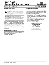
5. Disconnect negative ground wire (black wire) from
the battery’s negative post ( - ). Place ground wire in
a location where it cannot touch the battery posts.
Remove Ground Wire From Battery
Figure 1
Negative Post
BlackNegative
Battery Cable
Positive Post
Located Under
Red Cover
Red Positive
Battery Cable
24576
For Z48, Z54, ZSR54 & ZSR60 Zero Turn Mowers
Electric Deck Lift
Assembly Instructions
9/16/11
Manual No. 357-372M
2
Electric Deck Lift Assembly Instructions Manual No. 357-372M 9/16/11
Assembly Instructions
Toggle Switch Location
Refer to Figure 2:
Cut 15/32" diameter hole through console decal in the
location shown to expose pre drilled hole under the
decal.
Deck Lift Decal Installation
Refer to Figure 3:
1. Clean area around the hole with soap and water and
then dry with a clean soft cloth.
2. Without removing the backing paper, position the
deck lift decal (#11) over the hole with the down
arrow pointing towards the front of the mower.
3. Hold decal in place while removing one-half of the
backing paper and then press that side down.
4. Remove remaining backing paper and press the
other decal half down. Smooth out decal to remove
all air bubbles.
Remove Console Panel
Refer to Figure 4:
1. Raise seat up and locate on the right side the cable
tie securing cables leading to the console panel.
2. Cut cable tie to free up cables so that the console
panel can be lifted up to expose wiring below.
Refer to Figure 2:
3. Remove screws "A" and keep for reuse.
4. Lift console panel up to expose wiring below.
Console Panel Controls & Toggle Switch Location
Figure 2
Proper Orientation of Deck Lift Decal
Figure 3
Remove Cable Tie Securing Console cables
Figure 4
Hour
Meter
Blade
Engagement
Switch
Ignition
Switch
26501
Throttle
Lever
Choke
Knob
13/16"
1 5/16"
Cut 15/32" Dia. Hole
Through Console Decal
A
A
26502
Toggle Switch
Hole
11
Cut Cable Tie
BeforeRemoving
Console Panel
30130
Cables Leading
to Console Panel
3
9/16/11
Electric Deck Lift Assembly Instructions Manual No. 357-372M
Assembly Instructions
Wire Harness Routing
Refer to Figure 6 & Figure 7:
1. Remove the two fuse covers “G1” and 30 amp
fuses “G2” from fuse mounts “G3” on wiring
harness (#10).
Refer to Figure 5 & Figure 7:
2. Route orange and yellow eyelets “E” & “F”, 30 amp
fuse mounts “G”, actuator plug “H” and wiring
harness (#10) through hole in bottom of console.
3. Pull wiring harness through hole until most of
harness is outside of the console area. Keep
terminals “A”, “B”, “C” & “D”, toggle switch “J” and
relay switch “K” inside the console cavity.
4. Replace 30 amp fuses and fuse covers.
Insert Wire Harness Through Hole in Console Cavity
Figure 5
Wire Harness Terminal Connections
Refer to Figure 8:
1. Locate hour meter and its terminals on the backside
of the console panel.
2. Notice that the gray wire is attached to the positive
terminal (+) and black wire to the negative (-)
terminal. Disconnect the two wires from the hour
meter.
Refer to Figure 7 & Figure 8:
3. Attach deck lift wiring harness (#10) to the hour
meter as follows:
Attach gray wire with female terminal “B” to the
positive (+) terminal on the hour meter.
Attach black wire with female terminal “D” to the
negative (-) terminal on the hour meter.
4. Attach deck lift wiring harness (#10) to wires pulled
from the hour meter as follows:
Attach gray wire with male terminal “A” to the gray
wire pulled from the hour meter.
Attach black wire with male terminal “C” to the
black wire pulled from the hour meter.
30135
Hole In bottom of
Toggle Switch “J”
Relay Switch “K”
30 AMP Fuses “G”
Figure 6
Wiring Harness (#10)
Figure 7
Wire Harness Terminal Connections
Figure 8
30143
Remove Covers and
30 AMP Fuses Before
Threading Wiring
Harness Through Hole
In Bottom of Console.
G2
G3
10
G1
30083
J
D
B
E
F
C
A
H
G
K
10
26503
Attach Gray Wire With
Female Terminal “D” To
Positive (+) Terminal.
Attach Black Wire With
Female Terminal “B”
To Negative (-) Terminal
Existing Wires Disconnected From Hour Meter
Attach Black Wire With
Male Terminal “C”
To Existing Black Wire
Attach GrayWire With
Male Terminal “A”
To Existing Gray Wire
Hour Meter
10
4
Electric Deck Lift Assembly Instructions Manual No. 357-372M 9/16/11
Assembly Instructions
Toggle Switch Installation
Refer to Figure 9:
1. Remove knurled nut from toggle switch.
2. Turn hex jam nut on toggle switch all the way down.
3. Position toggle switch with keyed notch in threads
facing towards the back (UP arrow side of decal).
4. Insert switch through 15/32" hole and secure with
knurled nut. Hand tighten nut. Pliers may be used to
tighten the knurled nut a little tighter.
Toggle Switch Installation
Figure 9
Refer to Figure 10:
5. Replace console panel and tighten screws “A” at
both ends of the panel.
6. Insert toggle switch boot (#12) over toggle switch
lever and tighten nut.
Toggle Switch Boot Installation
Figure 10
Refer to Figure 11:
7. Reattach existing console cables to mower side
panel with cable tie (#1). Cut excess end of tie off.
Secure Console Cables With New Cable Tie
Figure 11
Locate Deck Toggle
Switch with keyed notch
on the Up Arrow Side
Knurled Nut
26506
26515
12
A
30130
Cables Leading
to Console Panel
1
Actuator Assembly
Refer to Figure 14:
1. Raise seat panel and locate lift arm pivot pin “P” on
the right side.
2. Remove painted tape from lift arm pivot pin.
Be sure all the tape and paint is remove from the
pivot pin.
Remove Paint From Pivot Arm
Figure 12
Refer to Figure 13:
3. Remove the cable tie fastened to the hole in the
engine upper fire wall so that carriage bolt (#4) can
be installed. See Figure 14 on page 5 for illustration
of carriage bolt (#4).
Remove Cable Tie Securing Engine Wire Harness
Figure 13
P
30132
Remove Cable Tie
Reference: Electric Deck Lift Bracket (#2)
To be installed later.
Engine Upper Fire Wall
30131
5
9/16/11
Electric Deck Lift Assembly Instructions Manual No. 357-372M
Assembly Instructions
Refer to Figure 15:
1. Attach wiring harness (#10) to actuator receptacle
with actuator plug “H”.
Connect Wire Harness to Actuator Receptacle
Figure 15
30128
H
10
Actuator Assembly
Figure 14
Remove Cable Tie Before
Inserting Carriage Bolt (#4)
Actuator Rod
Upper Fire Wall
Lower Fire Wall Lip
P
27906
Refer to Figure 14:
4. Attachelectricdeckliftbracket(#2) toengine firewall
byinsertingitsnotchedbottomontothelowerfirewall
lip and then bolting the top to the upper firewall with
the 3/8"-16 x 3/4" carriage bolt (#4) and hex flange
nut (#5). Tighten nut to 31 ft-lbs.
5. Slide base end of actuator (#9) onto lift arm “P”.
6. Slide 1/2" flat washer (#6A) onto lift arm “P” and
insert15/32" cotter pin(#7A). Bendone ormore legs
of the cotter pin to secure it in place.
7. Align rod end of actuator between the two long slots
in lift bracket (#2).
8. Insert 1/2" x 3 1/2" clevis pin (#8) through 1/2" flat
washer (#6B), slot in right side of lift bracket (#2),
1"spacer(#3A), actuator rod,1"spacer (#3B),slotin
left side of lift bracket (#2) and 1/2" flat washer (#6C).
9. Insert cotter pin (#7B) into clevis pin (#8). Bend one
or more legs of the cotter pin to secure it in place.
6
Electric Deck Lift Assembly Instructions Manual No. 357-372M 9/16/11
Assembly Instructions
Battery Hook-up
Figure 16
Battery Hook-Up
Refer to Figure 16:
1. Connectyelloweyelet“E” andred batterycable“Lto
the battery’s positive (+) post. Tighten fasteners at
the battery post and cover post with red cover “M”.
2. Connect orange eyelet “F” and black battery cable
“N” to the battery’s negative (-) post. Tighten
fasteners at the battery post.
3. Tie 30 AMP fuses “G” to existing mower wiring
harnesswith cabletie (#1). Cut excess end of tie off.
30128
E
L
F
N
M
1
10
G
Actuator Test Run
Test actuator for proper operation as follows:
Refer to Figure 13:
1. Turn switch key to run position. Raise mower deck
fully up by moving toggle switch (#12) back towards
“Arrow Up” position.
2. When fully up, stop handle "A" should drop into
transport notch "B".
Actuator Mount Installation (Rear Bolt)
Figure 17
Operating Instructions
Refer to Figure 17:
1. Raise deck up until stop handle "A" falls into the
transport notch "B" and then lower deck until stop
handle comes against the transport notch.
2. Place deck height adjusting stop "C" in a cutting
height gauge hole.
3. Raise deck up only enough to lift stop handle out of
thetransportnotch and then lowerdeckuntil the stop
handlecomesagainstthedeckheightadjustingstop.
A
C
B
26522
IMPORTANT: Use actuator only for lifting and
lowering the deck. Never carry deck weight with the
actuator. Always carry deck weight with stop
handle "A" against deck height adjusting stop "C" or
against transport notch "B".
9/16/11
Electric Deck Lift Assembly Instructions Manual No. 357-372M
7
Listing of Parts
1 800-112C CABLE TIE .19 X 7.25 1.75D . . . . . . . . . . . . . . . . . . . . . . . . . . . . . . . . . . . . . . . . 2
2 357-370H ELEC DECK LIFT BRACKET. . . . . . . . . . . . . . . . . . . . . . . . . . . . . . . . . . . . . . . . . 1
3 357-859D SPACER, 1ODX1/4WL. . . . . . . . . . . . . . . . . . . . . . . . . . . . . . . . . . . . . . . . . . . . . . 2
4 802-149C RHSNB 3/8-16X3/4 GR5 . . . . . . . . . . . . . . . . . . . . . . . . . . . . . . . . . . . . . . . . . . . . 1
5 803-068C NUT HEX FLANGE 3/8-16 PLT . . . . . . . . . . . . . . . . . . . . . . . . . . . . . . . . . . . . . . . 1
6 804-016C WASHER FLAT 1/2 SAE PLT. . . . . . . . . . . . . . . . . . . . . . . . . . . . . . . . . . . . . . . . . 3
7 805-089C PIN COTTER 5/32 X 1 1/2 LONG . . . . . . . . . . . . . . . . . . . . . . . . . . . . . . . . . . . . . 2
8 805-108C PIN CLEVIS 1/2 X 3 1/2 PLT . . . . . . . . . . . . . . . . . . . . . . . . . . . . . . . . . . . . . . . . . 1
9 833-466C ELECT. LINEAR ACTUATOR 4IN STK. . . . . . . . . . . . . . . . . . . . . . . . . . . . . . . . . . 1
10 833-490C HARNESS, ELECTRIC DECK LIFT - (See Figure 7 on page 3) . . . . . . . . . . . . . . 1
11 848-290C DECAL, DECK LIFT, UP DOWN - (See Figure 3 on page 2) . . . . . . . . . . . . . . . . . 1
12 833-499C BOOT, TOGGLE SWITCH - (See Figure 10 on page 4). . . . . . . . . . . . . . . . . . . . . 1
13 357-372M MANUAL, ELECTRIC DECK LIFT KIT, RAZOR. . . . . . . . . . . . . . . . . . . . . . . . . . . 1
Kit No. 357-371A ELECTRIC DECK LIFT KIT, RAZOR
Item Part No. Part Description Qty
Electric Deck Lift Kit (Items 10, 11 & 12 Not Shown)
Figure 18
27906
Corporate Office: P.O. Box 5060
Salina, Kansas 67402-5060 USA
www.landpride.com
  • Page 1 1
  • Page 2 2
  • Page 3 3
  • Page 4 4
  • Page 5 5
  • Page 6 6
  • Page 7 7
  • Page 8 8

Land Pride Z User manual

Category
Lawnmowers
Type
User manual
This manual is also suitable for

Ask a question and I''ll find the answer in the document

Finding information in a document is now easier with AI