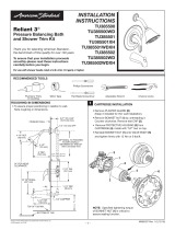
Recommended Tools
Channel Locks
Tubing CutterFlat Blade Screwdriver
Phillips Screwdriver
Adjustable Wrench
Pipe Wrench
Teflon Tape
Electric Drill
6mm
Hex wrench
5mm
Hex wrench
Level
ROUGHING-IN DIMENSIONS
2064.951
Certified to comply with ANSI A112.18.1
Installation
Instructions
Thank you for selecting American-Standard...
the benchmark of fine quality for over 100 years.
To ensure that your installation proceeds smoothly--
please read these instructions carefully before you begin.
11-5/16"
(287mm)
1-7/8" DIA.
(48mm)
12˚
24" MAX.
(609mm)
35-1/8" MAX.
(892mm)
42" MAX.
(1067mm)
IMPORTANT
NOTICE TO THE INSTALLER!
Please check with your local Code Authority
for acceptable installation requirements for
this Roman Tub set with hand shower. Some
local codes may require a vacuum breaker
and/or a pressure balanced mixing valve to
be installed in conjunction with this product.
*Adequate floor support is required.
The wood support must be a minimum
of 2" (51mm) thick by 10" (254mm) wide.
2x6 lumber is NOTadequate for
this application.
7"
(177mm)
47" MAX.
(1193mm)
LEVELING NUT
WASHER
LOCK WASHER
MOUNTING NUT
MOUNTING SCREW
26-15/16" MAX.
(684mm)
Contemporary Round
Floor Mounted Tub Filler
ESCUTCHEON
10" (254mm) MIN.
FLOOR JOIST
2-3/4"
70mm MIN.
1/2" NPT
FEMALE THREAD
COLD
1/2" NPT
FEMALE THREAD
HOT
FINISHED
FLOOR
FINISHED
FLOOR
4-3/4" x 4-3/4"
(120 x 120mm)
4" DIA.
(103mm)
*2" MIN.
(51 mm)
*WOOD SUPPORT
3/4"
(19mm)
PLASTER GUARD
Round Bubble Level
M965638 REV. 1.3 (10/15)

3
• Note: Refer to Roughing-in Dimensions on page one for additional information.
• Adequate oor support is required. The WOOD SUPPORT (1) must be a minimum of 2" (51mm) thick by 10" (254mm) wide.
2x6 lumber is NOT adequate for this application.
• Locate WOOD SUPPORT (1) between oor joists keeping a minimum distance of 2-3/4" (70mm) from the top surface of
wood support to the nished oor.
• IMPORTANT: Use a ROUND BUBBLE LEVEL (2) to level the WOOD SUPPORT (1). The WOOD SUPPORT (1) must
be perfectly level. Secure WOOD SUPPORT (1) to floor joists. Check for level again.
• Sweat together Hot and Cold Supply assemblies. Apply sealing tape to threaded connections. Thread supply assemblies
into rough-in valve inlets. The Hot inlet will be on the left when facing the front of the Tub Filler.
Note: The Hot and Cold inlets are marked on the manifold. See View “A”.
1
INSTALL HOT AND COLD WATER SUPPLIES
INSTALL TUB FILLER FLOOR SUPPORT
2
FRONT
Turn off hot and cold water
supplies before beginning.
CAUTION
FINISHED FLOOR LINE
2-3/4" (70mm)
MIN.
FLOOR JOIST
2 ROUND BUBBLE LEVEL
1 WOOD SUPPORT
10" (254mm) MIN.
2" (51mm) MIN.
10"-12" (254-305mm)
2
HOT
COLD
SEALING
TAPE
SUPPLY
ASSEMBLY
FRONT
HOT
COLD
View “A”
M965638 REV. 1.3 (10/15)

*Important: FRONT of ROUGH-IN VALVE (1) must face bath rim. Figure 1.
1
2
HOT
COLD
Fig. 2
FRONT
HOT
COLD
FINISH PLUMBING CONNECTIONS
LEVEL ROUGH-IN VALVE
4
• Locate the position on the wood support where the ROUGH-IN VALVE (1) will be installed.
Use the ROUGH-IN VALVE (1) as a guide to mark the four mounting hole locations. Fig. 1.
• Remove ROUGH-IN VALVE (1) and drill four pilot holes of 3/8" (9mm) in diameter. Fig 2.
• Install the 4 MOUNTING SCREWS (2) into wood support.
• Install ROUGH-IN VALVE (1) onto the 4 MOUNTING SCREWS (2) and tighten NUTS &
WASHERS (2) supplied.
• Complete all Hot and Cold supply connections.
• Turn on water supplies and ckeck for leaks.
INSTALL ROUGH-IN VALVE
3
1
1
3
FRONT
Fig. 1
HOT
COLD
*FRONT
• Check that top of the ROUGH-IN VALVE (1) is level in all directions. If the ROUGH-IN VALVE (1) is not level follow the steps below.
1. Loosen the four MOUNTING NUTS (2).
2. Adjust the LEVELING NUTS (2a) until the TUB FILLER is level in all directions.
3. Tighten the four MOUNTING NUTS (2) and check that theTUB FILLER is still level. If adjustment is still required loosen
MOUNTING NUTS (2) and adjust LEVELING NUTS (2a).
• Verify that the ROUGH-IN VALVE (1) is level and then fully tighten NUTS & WEASHERS (2).
2
2a
LEVELING NUT
FLAT WASHER
LOCK WASHER
MOUNTING NUT
MOUNTING SCREW
M965638 REV. 1.3 (10/15)
NOTE: IF INSTALLING ON A CONCRETE SLAB
• Drill four pilot holes of 12.5mm (1/2") in diameter.
• Insert a concrete anchor in each pilot hole.
• Install the 4 MOUNTING SCREWS (2) into the 4 concrete anchors.
Tighten NUTS & WASHERS (2) supplied.
*
Concrete anchor not included. But available commercially.
Concrete Anchor
S12 (12mm)

• Complete the installation of the Finished Floor. Tile as close to the PLASTER GUARD (3) as you can.
• Caulk between Finished Floor and PLASTER GUARD (3).
4
REMOVE EXPOSED PLASTER GUARD
6
• Cut the exposed part of the PLASTER GUARD (3) ush with the nished oor. Be careful not not damage the oor.
FINISH FLOOR INSTALLATION
5
1
HOT
COLD
FRONT
FINISHED FLOOR
ROUGH FLOOR
3
3
1
HOT
COLD
FRONT
FINISHED FLOOR
M965638 REV. 1.3 (10/15)

• Remove the two TEST PLUGS (6) with a (6mm)
hex wrench.
REMOVE HOT AND COLD TEST PLUGS
7
• Remove the SIX RETAINING PLATE SCREWS (4)
with a (5mm) hex wrench.
• Remove RETAINING PLATE (5).
REMOVE RETAINING PLATE AND SCREWS
8
Note: Floor is not shown for clarity in this illustration.
5
1
HOT
COLD
FRONT
FINISHED FLOOR
4
5
6
5mm HEX
WRENCH
6mm HEX
WRENCH
M965638 REV. 1.3 (10/15)

6
10
12
11
INSTALL TUB FILLER
INSTALL TUB FILLER
9
9a
8
7
Note: A minimum of four MOUNTING SCREWS (10) are required
to secure the tub filler. All six are preferred.
• Install the MOUNTING SCREWS (10) through the
MOUNTING PLATE (11) and into the manifold base.
Do not fully tighten.
• Rotate the TUB FILLER (12) right or left to
align with Tub. Tighten MOUNTING SCREWS (10)
with 5mm Hex Wrench to secure TUB FILLER (12).
9
COLD
COLD
FRONT
HOT
HOT
(VIEW “A”)
(VIEW “A”)
COLD
HOT
• Before nal installation, check that all sealing surfaces are
clean and that the INLET HOSE O-RINGS (7) are
not damaged.
Important: INLET HOSE O-RINGS (7) can be
damaged if caution is not used when installing.
Match inlet hose marked with a blue dot with
the hole on the manifold also marked with
blue dot. (VIEW “A”)
• Install the INLET HOSES (8) into the
MANIFOLD MOUNTING BASE (9).
BLUE DOT
(COLD)
BLUE
DOT
RED DOT
(HOT)
RED
DOT
5mm HEX
WRENCH
M965638 REV. 1.3 (10/15)

FINISHED FLOOR
APPLY SEALANT
• Move HANDLE (23) onto “off” position and remove STREAM
STRAIGHTENER (24) with KEY (25) supplied.
• Turn on water supplies and check all connections for leaks.
Check MANIFOLD (26) connections for leaks.
• Apply sealant to underside edge of ESCUTCHEON (27). Slide
ESCUTCHEON (27) down to nished oor. Press into place.
Clean up excess sealant.
• Operate HANDLE (23) On to Off and Hot to Cold to ush water
lines thoroughly.
• Lift HAND SHOWER (21) from the HOLDER (22) and direct spray into
tub. Rotate DIVERTER KNOB (28) and check HAND SHOWER (21)
and SPRAY HOSE (19) connections for leaks.
• Rotate DIVERTER KNOB (28) back and place HAND SHOWER (21)
into HOLDER (22).
• Re-install STREAM STRAIGHTENER (24).
TEST INSTALLED FAUCET
7 1
• Align slot in RETAINING RING (13) with SET SCREW HOLE (14) in SPOUT (15).
Install SPOUT (15) onto FAUCET BASE (16). Align SPOUT (15) with bath and
tighten SET SCREW (17). (VIEW “B”)
• Install SEALS (18) on both ends of the SPRAY HOSE (19). Connect the end with
the hex to the DIVERTER (20) using an adjustable wrench. Hand tighten the
connection to the HAND SHOWER (21).
Note: When not in use, the HAND SHOWER (21) should
be seated in the SHOWER HOLDER (22).
INSTALL SPOUT AND HAND SHOWER
9b
15
19
23
26
21
18
24
15
20
17
17
14
13
22
25
16
28
27
(VIEW “B”)
(VIEW “B”)
M965638 REV. 1.3 (10/15)

8
MODEL NUMBER
M964978-0070A
AERATOR KIT
2064.951
002
295
Replace the "YYY" with
appropriate nish code
POLISHED CHROME
SATIN NICKEL
M964971-YYY0A
ROUND HAND SHOWER
AND HOSE
M964972-YYY0A
ROUND HANDLE KIT
M964976-YYY0A
ROUND SHOWER
BRACKET KIT
M951472-0070A
CARTRIDGE
M964979-0070A
INLET ADAPTER
O-RING KIT
M962653-0070A
CARTRIDGE NUT
M964975-YYY0A
ROUND DIVERTER KIT
M964980-0070A
SPOUT SET SCREW
AND SEAL KIT
Contemporary Round
Floor Mounted Tub Filler
M965638 REV. 1.3 (10/15)
HOT LINE FOR HELP
For toll-free information and answers to your questions, call:
1 (800) 442-1902
Mon. - Fri. 8:00 a.m. to 8:00 p.m. EST
Saturday 10:00 a.m. to 4:00 p.m. EST
IN CANADA 1-800-387-0369
(TORONTO 1-905-306-1093)
Weekdays 8:00 a.m. to 7:00 p.m. EST
IN MEXICO 01-800-839-1200
Product names listed herein are
trademarks of AS America, Inc.
© AS America, Inc. 2015
/

