Page is loading ...

AN-861 Guide to CRT Video Design
Literature Number: SNOA268

TL/H/11733
Guide to CRT Video Design AN-861
National Semiconductor
Application Note 861
Zahid Rahim
January 1993
Guide to CRT Video Design
INTRODUCTION
This application note provides a design guide for success-
fully designing high frequency CRT video boards. For better
illustration, an example of a complete video board design
using the LM1203N RGB preamplifier and the LM2419 RGB
CRT driver is provided. The design includes: DC restoration,
contrast control, brightness control, cutoff adjustment, delta
gain adjustment (for white balance) and blanking at grid G1.
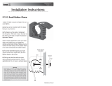
The complete circuitry for the video board is shown in
Fig-
ure 13. Figure 1
shows the pulse response at the cathode
fora45V
PP
output signal. Rise and Fall times at the cath-
ode were measured at 6 ns and 7.5 ns respectively and
settling time (to within
g
5% of final value ) was measured
at 20 ns. The overshoot and undershoot were measured at
5V. An NEC-5D multi-sync monitor was used to evaluate the
video board, the performance of the video board was very
good at 1024 x 1024 display resolution. Various sections of
Figure 13’s
circuit are described below in detail.
1.0 RGB PREAMPLIFIER (LM1203)
The LM1203 is a wideband video amplifier system specifi-
cally designed for RGB CRT monitor applications (Refer-
ence 1ÐLM1203 Data Sheet). The device includes three
matched video amplifiers, three matched attenuator circuits
for contrast control, and three gated differential input clamp
comparators for black level clamping of the video signal. In
addition, each video amplifier includes a gain adjustment or
‘‘drive’’ pin for individual gain adjustment of each video
channel to allow white balance adjustment.
1.1 RGB Video Signals
The RGB video signals are AC coupled to the inputs of the
LM1203 preamplifier. As shown for the Green channel (see
Figure 13
), C1 AC couples the video signal and R8 refer-
ences the signal to 2.4 V
DC
reference voltage from pin 11.
The 75X resistor, R1, is a termination resistor whose value
matches the characteristic impedance of the 75X coaxial
cable. Note that if a 50X video generator is used with 50X
coaxial cables to test the video board then 50X termination
resistors should be used.
In the absence of R2, the stray input capacitance of the
LM1203 would effectively short R1 at high frequencies
causing reflections. The 33X resistor, R2 maintains reason-
able termination at high frequencies thereby minimizing re-
flections. Note that the value of R2 should not be much
larger than 33X otherwise the rise and fall times of the out-
put signal would be degraded.
1.2 Gain Adjustment and Black Level Clamping
Potentiometers R16 and R25 allow the user to adjust the
gain of the Blue and Green channels respectively for
achieving correct white balance. The gain of the Red chan-
nel is fixed by resistor R20. Once white balance is achieved,
the contrast control potentiometer R11A allows the user to
adjust the gain of all three channels simultaneously.
The black level control potentiometer, R27, allows the user
to clamp the black level of the video signals to the desired
level. Potentiometer R27 should be adjusted such that the
video signals at the output of LM2419 (CRT driver) are bi-
ased within LM2419’s linear operating region. To accom-
plish black level clamping, however, a back porch clamp
signal must be applied to the clamp gate input (pin 14) of
LM1203. The MM74HC86 quad exclusive-or gate generates
the required back porch clamp signal (see section 4.0).
1.3 Preamplifier Gain Peaking for Improved Rise and
Fall Times
Connecting a small capacitor from LM1203’s drive pins
(pins 18, 22 and 27) to ground peaks the amplifier’s high
frequency gain and increases the
b
3 dB frequency. Using
18 pF peaking capacitors (C100, C101 and C102 in
Figure
13
), LM1203’s bandwidth is 70 MHz and rise/fall times un-
der 7 ns. If the LM1203 is used to directly drive the LM2419
without the buffer transistors Q1, Q2 and Q3 then 33 pF
peaking capacitors should be used. Refer to the LM1203
data sheet for information on frequency response using var-
ious peaking capacitor values. To minimize overshoot, the
peaking capacitor should be less than 60 pF.
1.4 Buffered Output
Some CRT drivers have large input capacitance which
makes it difficult for the preamplifier to directly drive the
CRT driver and yet maintain the required bandwidth. In such
applications, a buffer transistor is used between the pream-
plifier and the CRT driver (for example, transistor Q1 for the
Green channel in
Figure 13
). The buffer transistor used
should have a high f
T
at high currents. The LM1203 can
directly drive the LM2419 without sacrifice in bandwidth.
However, buffer transistors have been used in our design to
illustrate a complete design. The overall response of
Figure
13’s
circuit is similar with or without the buffer transistors. A
2N5770 transistor was selected which has a minimum f
T
of
900 MHz. Note that for fast fall time, the emitter resistor of
the buffer transistor should not be much larger than 330X.
C
1995 National Semiconductor Corporation RRD-B30M115/Printed in U. S. A.

TL/H/11733– 1
(a)
TL/H/11733– 2
(b)
TL/H/11733– 3
(c)
FIGURE 1. Pulse Response at the Cathode for
Figure 13
’s Circuit
2

2.0 RGB CRT DRIVER (LM2419)
The LM2419 is a high-voltage, wide-bandwidth amplifier that
drives the CRT’s cathodes (Reference 2ÐLM2419 Data
Sheet). The outputs of the LM2419 are AC coupled to the
cathodes (see
Figure 13
) so that cutoff voltages greater
than 80V can be accommodated at the cathodes. Further-
more, large variation in cutoff voltages can be accommodat-
ed because of the 120V supply. With the video signal AC
coupled to the cathode, the signal’s DC information is lost.
To restore the DC information of the video signal, the video
signal’s black level is clamped at the cathode.
2.1 Black Level Clamping (DC Restoration)
Figure 2
shows the black level clamping circuitry for the
Green channel. Capacitor C25 AC couples the video signal
to the cathode. Transistor Q4 and diode D8 clamp the sig-
nal’s black level to a voltage two diode drops greater than
the voltage at the base of Q4. Adjusting the voltage at the
base of Q4 using potentiometer R44 adjusts the clamp volt-
age thereby providing cutoff adjustment. Note that if the vid-
eo signal has a sync tip then the clamp circuit will clamp the
sync tip to the clamp voltage. The transistor selected for Q4
should have a BVCEO rating greater than 120V and low
junction capacitance. For our design, an MPSA92 PNP tran-
sistor was selected. Diode D7 is used to protect transistor
Q4 from an arc-over. D7 clamps Q4’s emitter to a diode
drop above 120V and provides a low impedance path for
the arc-over current to flow through D8 and D7 to the 120V
supply. The diodes used should have a high current rating,
low series impedance and low shunt capacitance. An
FDH400 diode is recommended.
2.2 Arc Protection
The CRT driver must be protected from arcing within the
CRT. To limit the arc-over voltage, a 200V spark gap should
be used at each cathode. Diodes D1 and D2 (see
Figure 3
)
clamp the voltage at the output of LM2419 to a safe level.
The clamp diodes used should have a high current rating,
low series impedance and low shunt capacitance. FDH400
or equivalent diodes are recommended. Resistor R54 in
Fig-
ure 3
limits the arc-over current while R33 limits the current
into the CRT driver. Limiting the current into the CRT driver
limits the power dissipation of the output transistors when
the output is stressed beyond the supply voltage. The resis-
tor values for R33 and R54 should be large enough to pro-
vide optimum arc protection but not too large that the ampli-
fier’s bandwidth is adversely affected.
Grids G1 and G2 should also have spark gaps. A 300V and
a 1 kV spark gap are recommended for G1 and G2 respec-
tively. The PC board should have separate circuit ground
and CRT ground. The board’s CRT ground is connected to
the CRT’s ground pin and also directly connected to the
chassis ground. The spark gap’s ground return should be to
the CRT ground so that high arc-over ground does not di-
rectly flow through the circuit ground and damage sensitive
circuitry. At some point on the PC board, the circuit ground
and the CRT ground should be connected. Often a small
resistor is connected between the two grounds to isolate
them (see
Figure 3
).
2.3 Overshoot Compensation
LM2419’s overshoot is a function of both the input signal
rise and fall times and the capacitive loading. The overshoot
is increased by either more capacitive loading or faster rise
and fall times of the input signal. The circuitry to reduce
overshoot is shown in
Figure 4.
Without the compensation
circuit (i.e. without R2 and C1) the overshoot and under-
shoot for the PC board of
Figure 10
were measured at 10%
and 15% respectively (V
OUT
e
40 V
P-P
). With the compen-
sation circuit in place (i.e. with R1
e
24X,R2
e
3.9 kX and
C1
e
3 pF), overshoot and undershoot were reduced to 0%
and 3.8% respectively. Inclusion of the compensation cir-
cuitry caused the rise and fall times to increase by 1 ns.
The values for the compensation circuit will depend on PC-
board layout and LM2419 loading. Here’s how to select the
correct component values for the compensation circuit
shown in
Figure 4
:
(a) R1 and R2 reduce the gain of the CRT driver at high
frequencies thereby reducing overshoot.
(b) C1 determines the frequency at which gain is reduced
and introduces a time constant in the pulse response.
(c) The time constant,
u
e
R2
c
C1 should be less than
20 ns. Capacitor C1 should be selected to be 3 pF or
slightly larger so as to eliminate the effect of stray ca-
pacitance. If C1 is too large such that
u
n
20 ns then
the pulse response will be damped, causing long rise
and fall times and therefore picture smearing.
(d) Making R2 too large will cause a damped pulse re-
sponse, giving rise to picture smearing. If there is a need
to change the high frequency gain to adjust the level of
overshoot then the value of R1 should be changed
since this will not affect the time constant.
TL/H/11733– 4
FIGURE 2. Black Level Clamp Circuit for DC Restoration
3

(e) With the value of R2 fixed, increasing the value of R1
will decrease the high frequency gain and therefore re-
duce the amplitude of the overshoot. Conversely, de-
creasing the value of R1 will increase the high frequen-
cy gain and therefore increase the amplitude of the
overshoot.
(f) Suggested initial starting values for
Figure 4
’s circuit are:
R1
e
24X to 100X,C1
e
3pFto6pF,R2
c
C1
k
20 ns.
Figure 5
shows the pulse response at the output of LM2419,
with and without compensation.
TL/H/11733– 5
FIGURE 3. Arc Protection Circuit
TL/H/11733– 15
FIGURE 4. Overshoot Compensation Circuit for LM2419
4

TL/H/11733– 16
(a)
TL/H/11733– 17
(b)
FIGURE 5. Pulse Response with and without Overshoot Compensation
2.4 Suppressing Oscillation
As is the case with all wideband amplifiers, PC-board layout
precautions must be taken to prevent oscillation. Experi-
mentation had shown that when the LM2419’s output was
probed with a passive probe (100:1, 5 kX probe) connected
toa50Xoscilloscope, the LM2419’s output burst into oscil-
lation. However, when probed with a high input impedance
(1 MX) FET probe the oscillation was not present. Further
investigation showed that the oscillation was caused by: the
inductance of the trace connected between the LM1203’s
output and the LM2419’s input; type of loadingÐin this
case, the complex impedance of the 5 kX passive probe;
and high frequency channel-to-channel cross-talk internal to
LM2419. The oscillation can be eliminated by applying the
following guidelines:
(a) Minimize trace length between the preamplifier output
and LM2419 input. If long trace length is unavoidable
then use low value (22X for example) series resistors
with short lead length in the signal path to damp the
inductance of the trace. Use carbon resistors and avoid
using wire wound resistors because they are inductive.
5

(b) Avoid long wires to connect the LM2419 output to CRT
socket. Inductance of the wire can cause ringing and
possible oscillation depending on the characteristics of
the complex load. Use a low value resistor (50 X for ex-
ample) in series with the output of LM2419 to damp the
wire’s inductance. Since the input impedance of the
LM2419 is high, the device is susceptible to high fre-
quency cross-talk. If oscillation still persists then lower-
ing the input impedance of LM2419 by connecting a
1kXresistor from LM2419’s input to ground solves the
problem (R500, R501 and R502 in
Figure 13
). The 1 kX
value is empirically determined, a lower value may be
required depending on the PC-board layout and load
characteristics.
Two 50X series resistors between LM1203 output and
LM2419 input were required to damp the inductance of the
signal trace. Note that in this application, the LM1203 was
used to directly drive the LM2419 without the use of buffer
transistors. When the series resistors were changed from
carbon to wirewound, the oscillation reappeared because of
the inductive characteristics of the wirewound resistors.
Oscillations can often occur due to ground loop currents.
Having separate power and low voltage ground planes will
help. Refer to Section 7.2 for further details.
2.5 Improving Rise and Fall Times
Because of an emitter follower output stage, the rise and fall
times of the LM2419 are relatively unaffected by capacitive
loading. However, the series resistors (R33 and R54 for the
Green channel, see
Figure 13
) will increase the rise and fall
times when driving the CRT’s cathode which appears as a
capacitive load. The capacitance at the cathode typically
ranges from 8 pF to 12 pF and every effort is made to mini-
mize this capacitance.
To improve the rise and fall times at the cathode, a small
inductor is often placed in series with the output of the am-
plifier. The series peaking inductor peaks the amplifier’s fre-
quency response at the cathode thus improving the rise and
fall times. The value of the inductor is empirically deter-
mined. An inductor value of 50 nH is a good initial starting
value. Note that peaking the amplifier’s frequency response
will increase the overshoot. Therefore the value of the in-
ductor selected is a compromise between optimum rise and
fall times and acceptable overshoot.
At low output voltage swing (for ex: V
OUT
k
5V
P-P
), the rise
and fall times may degrade by as much as 50% or more.
This is caused by the fact that LM2419 has a class ‘‘B’’
output stage with a 600 mV dead band, thus giving rise to
cross-over distortion. Increased rise and fall times may give
rise to picture smearing at low contrast settings. Connecting
a20kX((/2W) resistor from LM2419’s output to ground
biases the output stage in class ‘‘A’’ mode thus maintaining
similar rise/fall times at both small and large output voltage
swing.
2.6 Short Circuit Protection
The output of the LM2419 is not short circuit protected.
Shorting the output to either ground or to V
a
will destroy
the device. The minimum DC load resistance the LM2419
can drive without damage is 1.6 kX to ground or to V
a
.
However, driving a 1.6 kX load for an extended period of
time is not recommended because of power dissipation
considerations. If the LM2419 is used to drive a resistive
load then the load should be 10 kX or greater.
3.0 BLANKING AT GRID G1
The circuit used to accomplish blanking is shown in
Figure
6.
A negative voltage is applied to grid G1 using the resistor
divider comprised of R58 and R60. Brightness control is
achieved by varying the bias at G1 using potentiometer
R60. Blanking at the grid is accomplished by R59, R62, D13
and C34.
TL/H/11733– 6
FIGURE 6. Circuitry for Blanking at the Grid
6

Resistor R62 biases the clamp diode D13. A 15 V
PP
blank-
ing signal is AC coupled through C34. Since the voltage at
node ‘‘B’’ can not go more than one diode drop above the
voltage at node ‘‘A’’, the blanking signal at G1 is clamped at
the G1 bias voltage.
During the blanking portion of the video signal, the blanking
signal goes low thus reverse biasing D13 and pulling G1
15V negative with respect to its normal bias voltage. This
action cuts off the CRT’s beam current during the blanking
interval and accomplishes blanking.
4.0 BACK PORCH CLAMP GENERATOR
A versatile backporch clamp generator circuit is shown in
Figure 7.
A quad exclusive-or gate (MM74HC86) is used to
generate the back porch clamp signal from the composite
H-Sync input signal. The composite H-Sync input signal may
have either positive or negative polarity. The logic level at
pin 11 (Flag Out) indicates the polarity of the H-Sync signal
applied to the clamp generator. The Flag output is a logic
low (less than 0.8V) if the H-Sync input signal has a nega-
tive polarity and is a logic high (greater than 2.4V) if the
H-Sync input signal has a positive polarity.
Regardless of the H-Sync input signal’s polarity, a negative
polarity H-Sync signal is output at pin 8. Furthermore, a neg-
ative polarity back porch clamp pulse is output at pin 3. The
width of the back porch clamp pulse is determined by the
time constant due to R28 and C12. For fast horizontal scan
rates, the back porch clamp pulse width can be made nar-
rower by decreasing the value of R28 or C12 or both. Note
that an MM74C86 exclusive-or gate may also be used, how-
ever, the pin out is different than that of the MM74HC86.
5.0 THERMAL CONSIDERATIONS
The LM1203 preamplifier does not require a heat sink. How-
ever, the LM2419 requires a heat sink under all operating
conditions. For the LM2419, the worst case power dissipa-
tion occurs when a white screen is displayed on the CRT.
Considering a 20% black retrace time in a 1024 x 768 dis-
play resolution application, the average power dissipation
for continuous white screen is less than 4W per channel
with 50 V
PP
output signal (black level at 75V and white level
at 25V). Although the total power dissipation is typically
12W for a continous white screen, the heat sink should be
selected for 13W power dissipation because of the variation
in power dissipation from part to part.
For thermal and gain linearity considerations, the output low
voltage (white level) should be maintained above 20V. If the
device is operated at an output low voltage below 20V, the
power dissipation might exceed 4.7W per channel (i.e., 14W
power dissipation for the device). Note that the device can
be operated at lower power by reducing the peak-to-peak
video output voltage to less than 50V and keeping the
clamped video black level close to the supply voltage.
Maximum ratings require that the device case temperature
be limited to 90
§
C maximum. Thus for 50
§
C maximum ambi-
ent temperature and 13W maximum power dissipation, the
thermal resistance of the heat sink should be:
i
SA
s
(90
b
50)
§
C/13W
e
3
§
C/W
5.1 Designing the Proper Heat Sink
Once the required thermal resistance of the heat sink has
been determined, the process of designing the heat sink
can begin.
Figure 8
shows the thermal resistance versus the
required volume for an anodized or painted aluminum heat
sink. Note that the curve in
Figure 8
is based on lab mea-
surement of (/8
×
and (/16
×
thick sheet aluminum and is only
intended as a design guide. The actual thermal resistance
of the heat sink is affected by many factors such as the
shape of the heat sink, the orientation of the heat sink, etc.
Once a heat sink is fabricated, its thermal resistance should
be measured under actual operating conditions. The follow-
ing calculations show how to design a heat sink for the
LM2419.
TL/H/11733– 8
FIGURE 8. Heat Sink Volume vs Thermal
Resistance for Anodized Sheet Aluminum
MM74HC86
TL/H/11733– 7
FIGURE 7. Backporch Clamp Pulse Generator Circuit
7

Worst case power dissipation for LM2419 (White screen)
e
13W
Required heat sink thermal resistance, i
SA
e
3
§
C/W
From thermal resistance curve in
Figure 6,
required volume
of Aluminum (Al)
e
2.2 cu
×
For a sheet of Al with thickness, T
e
*/32
×
,
required area, A
e
2.2 cu
×
/(*/32)
×
e
24 sq
×
e
8
×
x3
×
Therefore select an anodized or painted black aluminum
heat sink of dimension 8
×
x3
×
x*/32
×
. Note that if the heat
sink surface is bright or shiny then the thermal resistance is
going to be higher than an anodized or black painted sur-
face because of the heat sink’s lower emissivity.
5.2 Measuring the Thermal Resistance of the Heat Sink
Whether a heat sink is designed or a commercially designed
heat sink is used, the thermal resistance of the heat sink
should be measured under actual operating condition to en-
sure that the measured thermal resistance meets the speci-
fication. If the heat sink’s thermal resistance is higher than
the required thermal resistance then the CRT driver’s case
may operate at a temperature higher than the recommend-
ed operating temperature thereby adversely affecting the
long term reliability of the device.
To measure the heat sink’s thermal resistance, a thermo-
couple may be used. The LM2419’s metal tab is bolted on
to the heat sink with a screw, a washer and a lock nut. The
thermocouple’s wire should be securely tightened between
the washer and the tab. Next, with the video board mounted
in the monitor, the LM2419’s power dissipation should be
measured. The LM2419’s case temperature is then mea-
sured under the operating condition using the thermocouple
device. The measured thermal resistance is then calculated
as follows :
i
SA
e
(T
C
b
T
A
)/PD
where, T
C
e
Case temperature
T
A
e
Ambient temperature
PD
e
Power Dissipation
For our application, a */32
×
x6
×
x4
×
sheet of aluminum was
used under actual worst case operating condition. The mea-
sured thermal resistance of the shiny (unpainted) heat sink
was 5
§
C/W and decreased to 4
§
C/W after the heat sink was
painted black with an enamel spray paint. Optimizing the
shape of the heat sink could have improved the thermal
resistance to less than 4
§
C/W. This excercise illustrates
that the guidelines of section 5.1 can be used to design a
heat sink and proper characterization under actual worst
case operating conditions are needed to finalize the design.
5.3 Getting the Best Performance from the Heat Sink
For best results, the following guidelines should be followed:
(a) A thermal joint compound (such as Thermacote from
Thermalloy or the 340 silicone heat sink compound from
Dow Corning) should be used between the LM2419’s
metal tab and the heat sink. The thermal joint com-
pound is a grease that establishes a low thermal resist-
ance between the package and the heat sink by displac-
ing the air gaps.
(b) Proper torquing (i.e., mechanical stress) should be ap-
plied so that good thermal contact is established. A
torque of 6 lb-inch is commonly applied.
(c) The heat sink should be mounted vertically. This causes
the heat sink to lose heat most effectively because cold
air is drawn to the bottom of the heat sink, heated and
moved to the top of the heat sink by convection. Fur-
thermore, mounting the heat sink vertically is especially
useful for heat sinks with fins.
(d) Either an anodized heat sink should be used or black oil
paint or a dark varnish should be applied to the heat-
sink. This further reduces the heat sink’s thermal resist-
ance due to improved radiation heat transfer.
6.0 CONTROLLING ELECTROMAGNETIC
INTERFERENCE (EMI)
There are stringent requirements on the manufacturers of
electronic products to control the emission of electromag-
netic waves. Electromagnetic waves not only interfere with
radio and TV reception but may also affect other electronic
devices in the vicinity of the source of radiation.
Voltage spikes caused by fast switching currents and the
impedance of the supply line and ground connection can
give rise to EMI radiation. An effective way to combat such a
cause of EMI is by making use of power supply filtering and
generous use of ground plane on the printed circuit board.
The ground plane provides a low impedance return for the
fast switching current, thereby suppressing EMI radiation.
Sometimes an undetected very high frequency (several
hundred MHz) oscillation in the circuitry can give rise to sig-
nificant EMI radiation. Such high frequency oscillation may
not be noticeable when viewing images on the screen or
may go undetected if the oscilloscope used is bandwidth
limited when compared with the frequency of oscillation. By
looking at the amplitude and frequency spectrum of the EMI
radiation, one can discern the presence of high frequency
oscillation within the circuitry.
Often long wires carrying high frequency signals can be a
big contributor of EMI radiation. If that is the case then
shielded cables should be used and the shield should be
grounded at both ends. Grounding the shield at both ends
allows the signal’s return current to flow through the shield
at high frequencies. The return current on the shield gener-
ates a field that tends to cancel the conductor’s field there-
by minimizing EMI radiation.
Some very high frequency designs require the use of con-
ductive shield enclosures to minimize EMI radiation. In re-
sponse to the offending electromagnetic field, the shield
produces currents which in turn produce magnetic fields
that oppose and cancel the inducing field. A steel enclosure
provides excellent attenuation of EMI radiation through re-
flection and absorption loss (caused by exponential decay
of the electromagnetic wave’s amplitude as it travels
through the medium).
7.0 PC BOARD LAYOUT GUIDELINES
Optimum performance at high frequencies requires careful
attention to PC board layout. Before starting the PC board
layout the circuit schematic should be carefully studied, high
frequency signal paths and sensitive nodes should be
marked. Once a well thought out PC board layout plan has
been established, the actual board layout can commence.
The following guidelines are essential for PC boards de-
signed for 100 MHz or greater bandwidth.
8

7.1 Adequate Ground Plane
For high frequency layouts, a solid ground plane is a must.
The ground plane provides a low inductance path for the
circuit’s return current. Moreover, a ground strip between
two high frequency signal traces can reduce cross talk by
referring the stray capacitance between the traces to
ground.
Because of the many restrictions placed on the layout, a
two sided board is recommended for bandwidths greater
than 100 MHz. On a two sided PC board, a full ground plane
is placed on the component side, for example the top side
of the board. Signal traces are then routed on the bottom
side of the board, this minimizes stray capacitance and im-
proves the isolation between high frequency signal paths
because the traces can be widely separated without affect-
ing PC board real estate. Furthermore, a two sided board
also greatly reduces the number of jumpers required when
compared with a single sided board thus allowing optimum
layout. A double sided board, however, adds to the cost of
the board. A double sided board may cost 30% more than a
single sided board. Increasing competition for high volume
and low cost consumer products often necessitate the
choice of a single sided board. If designed right, a single
sided PC board can provide acceptable performance at
100 MHz.
When laying out a single sided PC board, every attempt
should be made to layout a solid unbroken ground plane.
Figure 9(a)
shows ground voids along each column of pins
of the IC and is not recommended for high frequency layout
because it breaks up the flow of ground plane from the left
to the right. Such a layout may also compromise the stability
of the video amplifiers. The layout is improved by placing a
ground void around each pin (see
Figure 9b
) thus ensuring
a continuous flow of the ground plane from left to right.
Some designers use pin sockets to avoid soldering the IC to
the PC board. Pin sockets should be avoided if they reduce
the clearance between the pins and make it difficult to
achieve the layout of
Figure 9(b)
.
TL/H/11733– 9
FIGURE 9. Optimize High Frequency Layout by Having Ground Void around Each
Pin (b) instead of Ground Voids along the Entire Column of Pins (a).
9

Figure 10(a)
shows another common error made in many
PC board layouts. Trace ‘‘a’’ as shown in
Figure 10(a)
runs
both in the horizontal and the vertical direction thus break-
ing up the flow of the ground plane. Too many zig-zag
traces in the horizontal and vertical direction can render the
ground plane rather ineffective.
Figure 10(b)
shows that us-
ing jumpers to connect traces in the vertical direction main-
tains the flow of the ground plane from left to right. This
technique is especially necessary for single sided PC
boards. Note that the effect of jumpers in the signal path
must be considered. Normally jumpers are used in low fre-
quency signal paths. Furthermore, with careful planning,
passive components can often be used as crossunders
such that signal traces can pass under the components
thereby minimizing the number of jumpers required.
7.2 Avoiding Ground Loop
Often oscillations can occur due to ground loop currents.
When the CRT driver’s output slews at high frequencies,
large transient current is injected to the ground plane. If
both the preamplifier and the CRT driver share a common
ground plane then the transient current may couple to the
sensitive inputs of the preamplifier and may cause the pre-
amplifier to oscillate thereby causing both amplifiers to os-
cillate. The problem is severe if a wide bandwidth preamplifi-
er such as the LM1203B (100 MHz bandwidth) is used on a
single sided PC-board.
The LM1203
a
LM2419 CRT neck board (see
Figure 12
)is
a single sided board with a single ground plane. Because of
LM1203N’s limited bandwidth of 70 MHz, no oscillations
were observed. However, when the LM1203N was replaced
with the LM1203B, the LM1203B burst into oscillation. Sep-
arating the power ground (pin 5) of LM2419 from the
low voltage ground plane and making a single point ground
connection with the low voltage ground eliminated the oscil-
lation. So, the recommendations for laying out the PC-
board ground plane are as follows:
(a) The PC-board should be laid out with a separate power
ground plane for the CRT driver.
(b) The CRT driver’s power supply bypass capacitors
should be connected to the power ground plane.
(c) The power ground plane should be connected to the
low voltage ground plane at some point on the PC-
board. The best place to connect the two ground planes
should be empirically determined during the prototype
design phase.
Use of above guidelines may also reduce ringing at the pre-
amplifier’s output and therefore further improve the overall
system performance.
7.3 Power Supply Bypassing
Proper power supply bypassing is very critical for high fre-
quency PC board layout. The power supply should be a low
impedance point. However, the parasitic inductance of the
supply lead can cause the power supply to be high imped-
ance at high frequencies. Improper power supply bypassing
can not only produce excessive overshoot and ringing on
the amplifier’s pulse response but can also cause oscilla-
tion.
Both the LM1203 preamplifier and the LM2419 CRT driver
have very low power supply rejection, especially the
LM2419 which has 0 dB power supply rejection. Thus any
noise or ripple or transients, on LM2419’s power supply
pin will appear directly at the device’s output.
TL/H/11733– 10
FIGURE 10. Maintain a Continuous Flow of Ground Plane
by Avoiding Zig-Zag Traces (a) and by Making Use of Jumpers (b).
10

A high-frequency ceramic capacitor of value 0.01 mF should
be connected less than (/4 inch from the power supply pin of
the LM1203 and the LM2419. Note that for some wide-
bandwidth video amplifiers, the series inductance of the
0.01 mF capacitor is large enough to cause the amplifier to
oscillate and a 0.001 mF capacitor may be needed to sup-
press the oscillations. Since power supply bypassing is so
critical, one of the first things to do when starting the PC
board layout is to place the bypass capacitors first. Having
done so, the designer can then position the rest of the com-
ponents on the board.
In addition to a high frequency bypass capacitor, a large
bypass capacitor of value 10 mF or higher is also required.
The large bypass capacitor can be placed a reasonable dis-
tance from the supply pin. For LM1203 and the LM2419,
10 mF electrolytic or tantalum capacitor should be connect-
ed as close to each supply pin as is practical (see
Figure
13
). The large bypass capacitor acts as an energy storage
element and is the source of large transient currents when
driving capacitive loads. For example, 5 ns rise and fall
times when driving a 12 pF capacitive load at the output of
LM2419 would require 120 mA (i
e
C dV/dt
e
12 pF
c
50V/5 ns) current per channel. The 10 mF bypass capacitor
provides the 360 mA charge and discharge current for the
load while the voltage change on the power supply is only
180 mV
DV
e
3
c
i
c
Dt/C
e
3
c
120 mA
c
5 ns/10 mF
Also note that the supply connector of LM1203 and LM2419
are bypassed with a 100 mFanda47mF capacitor respec-
tively (see
Figure 13
).
Once the video board has been designed and is ready for
evaluation, the power supply pin of each IC should be
probed and the waveform observed on an oscilloscope. The
waveform on the power supply should be observed with the
video board operating at the maximum frequency. In a well-
designed and well-bypassed board, power supply ripple,
noise and transients would be minimum.
7.4 Optimizing the Layout of the High-Frequency
Signal Path
Figure 11(a)
shows that the components connected to the
video input and output pins are placed above the ground
plane. In wide bandwidth applications, the stray capacitance
from the component to the ground plane can reduce the
amplifier’s bandwidth.
Figure 11(b)
shows an improved lay-
out where a ground void (absense of ground plane) is
placed along the high frequency signal path. Note the large
ground void under the components and along the periphery
of the signal trace (see
Figure 11(b)
). Furthermore, a large
ground void is also placed around all components connect-
ed to the CRT socket as well as the CRT driver’s outputs.
Every effort should be made to minimize the length of the
video signal path. A long trace for instance will behave as a
transmission line if the trace length is greater than 1/15th
the wavelength of the highest frequency signal. Long trace
lengths along the high-frequency signal path can introduce
unwanted ringing and overshoot. If a long trace length is
unavoidable, then the trace length may be broken up by
resistors in series. By minimizing stray capacitance in the
layout and using small value series resistors, the reduction
in the amplifier’s bandwidth can be made negligible.
7.5 Minimizing Crosstalk
Capacitive coupling between two adjacent traces will give
rise to crosstalk. The greater the slew rate of the signal
propagating through the trace the larger the crosstalk.
Crosstalk can be minimized by increasing the separation
between traces. Also, a ground strip between high-frequen-
cy signal traces can reduce crosstalk by breaking up the
inter-trace stray capacitances and referring them to ground.
Lowering the impedance of the trace can also reduce cross-
talk but this may not always be practical. The following
guidelines are recommended:
a. Place a ground void along the high-frequency signal
trace (see
Figure 11b
).
b. Keep as much separation between high-frequency signal
traces as is possible.
c. Include ground plane between high-frequency signal
traces.
d. Keep output signals away from the inputs of the amplifier
and from other sensitive nodes in the circuit.
8.0 COMPLETE PC BOARD LAYOUT
A complete PC board layout of
Figure 13’s
circuit is shown
in
Figure 12
. The ground plane and signal traces are on the
bottom side of the board while the silk screen covers the
top side. The board makes generous use of ground plane in
and around the preamplifier and CRT driver sections. More-
over, jumpers are used to maintain a solid unbroken ground
plane.
The high frequency bypass capacitors are placed less than
(/4 inch from the power supply pins. Also, there is ground
void along the high frequency signal path and around the
CRT socket.
ACKNOWLEDGEMENT:
The author would like to acknowledge the contribution of
Ron Page for the backporch clamp generator circuit (see
Figure 7
) and Tom Mills for the thermal resistance curve
(see
Figure 8
).
REFERENCE:
1. LM1203 data sheet, National Semiconductor Corpora-
tion.
2. LM2419 data sheet, National Semiconductor Corpora-
tion.
11

TL/H/11733– 11
FIGURE 11. Using Ground Voids along the High-Frequency Signal Path Minimizes the Effect of Stray Capacitance
12

TL/H/11733– 12
FIGURE 12. Single Sided PC Board Layout of
Figure 13
’s Circuit
13

TL/H/11733– 13
FIGURE 13. Complete Circuit of CRT Video Board
14

TL/H/11733– 14
FIGURE 13. Complete Circuit of CRT Video Board (Continued)
15

AN-861 Guide to CRT Video Design
LIFE SUPPORT POLICY
NATIONAL’S PRODUCTS ARE NOT AUTHORIZED FOR USE AS CRITICAL COMPONENTS IN LIFE SUPPORT
DEVICES OR SYSTEMS WITHOUT THE EXPRESS WRITTEN APPROVAL OF THE PRESIDENT OF NATIONAL
SEMICONDUCTOR CORPORATION. As used herein:
1. Life support devices or systems are devices or 2. A critical component is any component of a life
systems which, (a) are intended for surgical implant support device or system whose failure to perform can
into the body, or (b) support or sustain life, and whose be reasonably expected to cause the failure of the life
failure to perform, when properly used in accordance support device or system, or to affect its safety or
with instructions for use provided in the labeling, can effectiveness.
be reasonably expected to result in a significant injury
to the user.
National Semiconductor National Semiconductor National Semiconductor National Semiconductor
Corporation Europe Hong Kong Ltd. Japan Ltd.
1111 West Bardin Road Fax: (
a
49) 0-180-530 85 86 13th Floor, Straight Block, Tel: 81-043-299-2309
Arlington, TX 76017 Email: cnjwge
@
tevm2.nsc.com Ocean Centre, 5 Canton Rd. Fax: 81-043-299-2408
Tel: 1(800) 272-9959 Deutsch Tel: (
a
49) 0-180-530 85 85 Tsimshatsui, Kowloon
Fax: 1(800) 737-7018 English Tel: (
a
49) 0-180-532 78 32 Hong Kong
Fran3ais Tel: (
a
49) 0-180-532 93 58 Tel: (852) 2737-1600
Italiano Tel: (
a
49) 0-180-534 16 80 Fax: (852) 2736-9960
National does not assume any responsibility for use of any circuitry described, no circuit patent licenses are implied and National reserves the right at any time without notice to change said circuitry and specifications.

IMPORTANT NOTICE
Texas Instruments Incorporated and its subsidiaries (TI) reserve the right to make corrections, modifications, enhancements, improvements,
and other changes to its products and services at any time and to discontinue any product or service without notice. Customers should
obtain the latest relevant information before placing orders and should verify that such information is current and complete. All products are
sold subject to TI’s terms and conditions of sale supplied at the time of order acknowledgment.
TI warrants performance of its hardware products to the specifications applicable at the time of sale in accordance with TI’s standard
warranty. Testing and other quality control techniques are used to the extent TI deems necessary to support this warranty. Except where
mandated by government requirements, testing of all parameters of each product is not necessarily performed.
TI assumes no liability for applications assistance or customer product design. Customers are responsible for their products and
applications using TI components. To minimize the risks associated with customer products and applications, customers should provide
adequate design and operating safeguards.
TI does not warrant or represent that any license, either express or implied, is granted under any TI patent right, copyright, mask work right,
or other TI intellectual property right relating to any combination, machine, or process in which TI products or services are used. Information
published by TI regarding third-party products or services does not constitute a license from TI to use such products or services or a
warranty or endorsement thereof. Use of such information may require a license from a third party under the patents or other intellectual
property of the third party, or a license from TI under the patents or other intellectual property of TI.
Reproduction of TI information in TI data books or data sheets is permissible only if reproduction is without alteration and is accompanied
by all associated warranties, conditions, limitations, and notices. Reproduction of this information with alteration is an unfair and deceptive
business practice. TI is not responsible or liable for such altered documentation. Information of third parties may be subject to additional
restrictions.
Resale of TI products or services with statements different from or beyond the parameters stated by TI for that product or service voids all
express and any implied warranties for the associated TI product or service and is an unfair and deceptive business practice. TI is not
responsible or liable for any such statements.
TI products are not authorized for use in safety-critical applications (such as life support) where a failure of the TI product would reasonably
be expected to cause severe personal injury or death, unless officers of the parties have executed an agreement specifically governing
such use. Buyers represent that they have all necessary expertise in the safety and regulatory ramifications of their applications, and
acknowledge and agree that they are solely responsible for all legal, regulatory and safety-related requirements concerning their products
and any use of TI products in such safety-critical applications, notwithstanding any applications-related information or support that may be
provided by TI. Further, Buyers must fully indemnify TI and its representatives against any damages arising out of the use of TI products in
such safety-critical applications.
TI products are neither designed nor intended for use in military/aerospace applications or environments unless the TI products are
specifically designated by TI as military-grade or "enhanced plastic." Only products designated by TI as military-grade meet military
specifications. Buyers acknowledge and agree that any such use of TI products which TI has not designated as military-grade is solely at
the Buyer's risk, and that they are solely responsible for compliance with all legal and regulatory requirements in connection with such use.
TI products are neither designed nor intended for use in automotive applications or environments unless the specific TI products are
designated by TI as compliant with ISO/TS 16949 requirements. Buyers acknowledge and agree that, if they use any non-designated
products in automotive applications, TI will not be responsible for any failure to meet such requirements.
Following are URLs where you can obtain information on other Texas Instruments products and application solutions:
Products Applications
Audio www.ti.com/audio Communications and Telecom www.ti.com/communications
Amplifiers amplifier.ti.com Computers and Peripherals www.ti.com/computers
Data Converters dataconverter.ti.com Consumer Electronics www.ti.com/consumer-apps
DLP® Products www.dlp.com Energy and Lighting www.ti.com/energy
DSP dsp.ti.com Industrial www.ti.com/industrial
Clocks and Timers www.ti.com/clocks Medical www.ti.com/medical
Interface interface.ti.com Security www.ti.com/security
Logic logic.ti.com Space, Avionics and Defense www.ti.com/space-avionics-defense
Power Mgmt power.ti.com Transportation and Automotive www.ti.com/automotive
Microcontrollers microcontroller.ti.com Video and Imaging www.ti.com/video
RFID www.ti-rfid.com
OMAP Mobile Processors www.ti.com/omap
Wireless Connectivity www.ti.com/wirelessconnectivity
TI E2E Community Home Page e2e.ti.com
Mailing Address: Texas Instruments, Post Office Box 655303, Dallas, Texas 75265
Copyright © 2011, Texas Instruments Incorporated
/