
585-123-01
SERVICE MANUAL
Monochrome Video Monitors
ZVM-1240/1240-E/1240-EM
7'''''H
I
data
systems
860-111

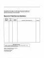
The purpose of this page is to make sure that all service bulletins are
entered
in
this manual. When a service bulletin is received, mark the man-
ual and list the information
in
the record below.
Record
of
Field
Service Bulletins
SERVICE DATE
BULLETIN
OF
CHANGED
NUMBER ISSUE PAGE(S) PURPOSE
OF
SERVICE BULLETIN
LIMITED
RIGHTS
LEGEND
Contractor
is
Zenith
Data
Systems
Corporation
of
St.
Joseph,
Michigan
49085.
The
entire
document
is
subject to
Limited
Rights
data provisions.
Copyright
©
1986
by Zenith
Data
Systems
Corporation
Printed
in
the United
States
of
America
Zenith
Data
Systems
Corporation
St.
Joseph,
Michigan
49085
INITIALS

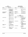
Contents
Characteristics
..
. . . . . . . . . . . . . . . . . . . . . . . . . . 1
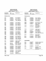
Parts Lists
..............................
19
Controls, Cables, and Indicators
..............
1
Specifications
..............................
2
Waveform Photograph Explanations
........
24
Installation
................................
3
Figures
Circuit Description .
........................
4
Power Supply
..............................
5
1.
ZVM-1240 and ZVM-1240-E Monitors
.....
1
High B + Indicating Circuit
...................
5
2.
ZVM-1240 and ZVM-1240-E Monitor Block Dia-
Video and Highlight Driver Circuits
............
5
gram
.................................
4
Horizontal Sweep
...........................
5
3.
AC
Leakage Voltmeter Circuit
............
8
Horizontal Output
...........................
6
4.
Main Board Component Location
........
13
Vertical Sweep
.............................
6
5.
Main Board Waveforms
................
13
Spot Burn Protection
........................
7
6.
ZVM 1240-/1240-E Schematic . . . . . . . . . . . 13
Brightness
.................................
7
7.
B+
Supply Component Location
........
14
Focus
....................................
7
8.
Waveform - Anode of CRX506
.........
14
Dynamic Focus
............................
7
9.
B+
Supply Schematic - ZVM-1240
......
14
10.
B+
Supply Schematic - ZVM-1240-E
....
14
Servicing
.................................
8
11.
CRT Board Component Location
........
15
Safety and Service Guidelines
................
8
12.
CRT Board Waveforms
................
15
AC Leakage Test
........................
8
13.
CRT Board Schematic
..
. . . . . . . . . . . . . . . 15
Other Precautions
........................
9
14.
ZVM-1240/1240-E Exploded View
........
16
Suggested Equipment and Supplies
...........
9
15.
Lead Dressing
........................
18
Tools and Supplies
.......................
9
Test Equipment
..........................
9
Troubleshooting
............................
9
Tables
Adjustments
..............................
11
B+
(+
16.2
V)
Voltage
..................
11
1 . General Troubleshooting
...............
10
Focus
.................................
11
2.
Circuit Board Troubleshooting
...........
10
CRT
yoke
.............................
12
3.
B + Supply Transistor Voltages
.........
14
Positioning
...........................
12
4.
Major Assemblies
.....................
19
Linearity . . . . . . . . . . . . . . . . . . . . . . . . . . . . . 12
5.
Electronic Components
..................
20
Cleaning Procedures
.......................
12
Servicing Diagrams
........................
12
Listings
Disassembly/Reassembly
..................
17
Back Cover (130)
.....................
17 1 . BASIC Program Used to Fill the Screen with a
CRT Board (125)
.....................
17 Character
.............................
3
Main Board (80)
......................
17
Control Mounting Bracket (40)
..........
18
Power Switch (110)
...................
18
CRT (10)
............................
18
Lead Dressing
........................
18


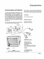
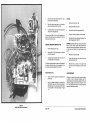
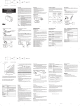
Controls,Cables, and Indicators
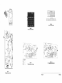
The ZVM-1240 monochrome video monitor is de-
signed to operate with a Zenith Z-100 Series or other
personal computer. The monitor accepts four TTL-
Level video signals (video input, highlight input, vertical
sync, and horizontal sync) at the 9-pin D-type connec-
tor of its shielded signal cable. A micromesh anti-glare
filter on an amber CRT provides viewing comfort
(on
the ZVM-1240-EM version only). The ZVM-1240 oper-
ates from 120 VAC and the ZVM-1240-E operates
from 240 V AC.
The Z-239 Video card is required when operating the
ZVM-1240 with a Zenith
PC
Series computer.
LED
POWER
INDICATOR
POWER
CORD
HORIZONTAL
HOLD
SIGNAL
CABLE
FRONT
Figure 1
ZVM-1240 and ZVM-1240-E Monitors
Characteristics
Refer to Figure 1 for the locations of the following ex-
ternal controls, indicators, and cables. Refer to Figure
4 for the locations of the following internal adjustments.
Front Panel
Power indicator LED, green
Side Panel Controls
Contrast control (upper)
Brightness control (lower)
ZVM-1240
Rear Panel Controls
Vertical Size control
Horizontal Hold control
Horizontal Width control
Power Switch
Power cable (wired into the monitor)
Signal cable (wired into the monitor)
Internal
B + Adjustment control
Master Brightness control
Focus control
Page
1

\
I
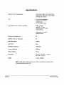
Specifications
Electrical Power Requirements . . . . . . . . . . .
CRT
.........................
.
Input Signals (9-pin, D-type connector). . . . . . .
Maximum Characters/Line . . .
Maximum Rows of Characters
Video Bandwidth
Rise Time
....
Horizontal Frequency.
Vertical Frequency
Vertical Retrace
Dimensions . . .
Weight
........................
.
10S-132 VAC, 60Hz, 0.4A. (ZVM-1240).
216-264 VAC, 50Hz, 0.2A. (ZVM-1240-E).
35 Watts (both models).
12-inch (30 cm) diagonal,
Amber (H-S), micromesh
anti-glare filter,
12.7 kV anode voltage.
Video, TTL level.
Highlight, TTL level.
Horizontal sync, TTL level,
(positive going).
Vertical sync, TTL level,
(negative going).
80.
25.
1SMHz.
20ns.
1S.432 kHz.
49.S2Hz.
750lJ-s.
10" (H) x 12.7"(W) x 11.S"(D).
(25 x 32 x 30 cm).
12.9 Ibs. (5.S5kg).
NOTE: Zenith Data Systems reserves the right to discontinue products and to
change specifications at any time.
Page 2
Characteristics

1. Place the video monitor
on
a horizontal surface
next to the computer and near
an
AC outlet.
CAUTION: The monitor must be located
in
an
area
that will provide proper ventilation. The air vents at
the bottom, back, and top of the monitor must not be
blocked.
2.
3.
4.
5.
Connect the video monitor signal cable between
the computer and the video monitor.
Connect the video monitor power cable to the
correct AC voltage.
Turn on the computer and the video monitor
power switches. The power indicator on the
front of the video monitor should light.
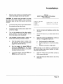
Use the BASIC program shown
in
Listing 1 to
fill the screen with any character as follows:
a.
Enter the program shown
in
Listing 1 into
the computer.
You
may want to save this
program on a disk for later use.
b.
Run the program by typing RUN and
pressing the
RETURN key. The screen
will be filled with the letter Z or any other
character inserted in line
20.
c.
To end the program, press the CTRL and
BREAK keys at the same time.
Installation
Listing 1
BASIC Program
Used
to Fill the Screen
with
a Character
10
FOR
I=l
TO
2000
20
PRINT
liZ";
'replace the
liZ"
with the
'character of your choice
30
NEXT
I
40
GO
TO
40
6.
7.
8.
Set the Contrast and Brightness controls fully
clockwise.
As
the CRT warms up, a raster should fill the
screen.
Adjust the Contrast and Brightness controls
as
desired. The suggested sequence is:
a.
Set the contrast for a slight raster.
b.
Set the brightness to a level that is pleas-
ant.
c.
Reset the contrast for a slight raster.
NOTE: Changes in room lighting or repositioning of
the monitor screen may require resetting the bright-
ness and contrast controls.
9.
Adjust the Vertical Size and Width controls to
fill the screen with raster.
10.
Adjust the Horizontal Hold control to lock in the
characters.
Page
3

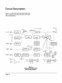
Circuit
Description
Figure
2,
a ZVM-1240
and
ZVM-1240-E
Block
Dia-
gram,
is
provided
for
tracing
signal
paths
while
study-
ing
circuit
descriptions.
+16.2VDC
MASTER
BRIGHTNESS
+500VDC
.--""""IV'--O
+
60
V DC
VIDEO
INPUT
00---1:>1
BRIGHTNESS
.....
~
___
.......,
FOCUS
+16.2VDC
HIGHLIGHT
INPUT
VERTICAL
SYNC
0o---DI
HORIZONTAL
f"8\
0---1:>1
SYNC
\V
HORIZONTAL
HOLD
Q)
~
CABLE
SHIELD
Page
4
CONTROL
120VAC
60Hz
ZVM-1240
Figure 2
ZVM-1240
and
ZVM-1240-E
Monitor Block Diagram
GRID
ANODE
13KV
HIGH
VOLTAGE
_L.-........I---I-
...
HORIZONTAL
OUTPUTI
TRANSFORMER
TX102
SOURCE
SOURCE
240VAC
50Hz
ZVM-1240-E

Refer to the following circuit descriptions for more in-
formation.
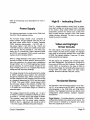
Power Supply
The
following description
is
written for the ZVM-1240.
The ZVM-1240-E oper,ates similarly.
The full-wave bridge rectifier circuit comprised of
diodes CRX501 through CRX504 rectify the
AC
volt-
age when power switch
SX501
is closed. Capacitor
CX507 develops approximately + 155 VDC with 1.7
Vpp
typical ripple
(+335
VDC for the -1240-E and
-1240-EM versions). CX508 and CX509 provide addi-
tional filtering. The
DC
potential of + 155 volts
is
ap-
plied to pin 12 of transformer TX502. Resistors RX505
and
RX510, and capacitor CX513 provide a self-start-
ing
bias circuit for transistor
OX501
.
When a voltage develops at the output of the bridge,
the base of
OX501
is driven positive, forcing the tran-
sistor into conduction. As a current path is established
through OX501, pin 10 of TX502 approaches chassis
ground potential. As current passes through the pri-
mary of TX502, pins 10 to 12, a magnetic field induces
voltage into both secondary windings.
The voltage induced into the winding tied to the emitter
of
OX501
-gradually goes positive until conduction
through the transistor stops. When conduction stops,
the field collapses and the collector-tuned circuit rings
at a frequency determined by CX512 and the primary
of TX502. This keeps
OX501
reverse biased. When
the
sine-wave voltage at the collector of
OX501
tries
to
go
negative, it induces a negative voltage at pin
7 of TX502 and the transistor begins to conduct to
saturation again.
The voltage induced into the winding, pin 1 to pin 2
of
TX502 is rectified by CRX506 and filtered by
CX511
to
provide a + 24 VDC input to the emitter of OX502.
This transistor, along with OX503, OX504, and as-
sociated circuitry, form the power supply regulator.
RX503 is the B + adjustment and should
be
set for
+ 16.2 VDC output. CRX505 is the power indicator.
Circuit Description
High B + Indicating Circuit
If
the B + voltage exceeds a certain level,
an
exces-
sively high voltage can develop and result in damage
to the monitor. Zener diode CR302 and associated
components prevent the vertical sync pulses from
being coupled through capacitor C316 if the excess
voltage condition develops. The lack of sync pulses
makes the monitor unusable.
Video and Highlight
Driver Circuits
The video signal
is
fed through resistor R212 to the
base of 0201, the video driver amplifier. The highlight
input
Signal
is fed through resistor
R221
to the base
of 0203, the highlight amplifier. These are TTL-level,
positive-polarity input signals.
The two signals are amplified and inverted by 0201
and
0203
respectively. The signals are combined at
the junction of R222 and 0201 collector. The Contrast
control, R402, is connected to the base of
0204
to
vary the bias voltage, thus controlling the signal current
through
0204
and 0202. 0202, the video output
amplifier, drives the cathode of the CRT, VX201.
Horizontal Sweep
The operation of the horizontal processor,
IC101
(221-
141-01), is the same as the 221-86-01, and they are
interchangeable in the ZVM-1240 and ZVM-1240-E
monitors. The integrated circuit has four distinct circuit
configurations; phase detector, oscillator, regulator,
and predriver.
Phase
Detector-The
phase detector is comprised of
a differential amplifier and a gated current source. The
current source is strobed by a negative sync signal
that is AC coupled to pin 3 of
IC1
01.
Page
5

The current division of the two transistors of the differ-
ential amplifier is determined by the phase relationship
between the sync and the sawtooth waveform
on
pin
4 of IC101. This sawtooth voltage
is
derived from posi-
tive horizontal flyback pulses. When the sync pulse
and sawtooth voltage are
in
phase, the current division
between the two transistors in the differential amplifier
will be equal. When there is a phase difference, current
will pass into or out
of
pin
5,
which is connected by
way of a low-pass filter to pin 7 of the oscillator. This
current controls the oscillator.
Oscillator-The
oscillator is an R-C type, with pin 7
being the control point. The timing capacitor,
C1
01,
is
charged by the external resistor, R104, to a trip volt-
age set
in
the integrated circuit. When this trip voltage
is reached, the capacitor discharges to a new trip
value. This process is repeated, producing a sawtooth
waveform at pin
7.
The output of the phase detector controls the oscillator
through resistive coupling from pin 5 to pin
7.
The hori-
zontal hold control,
R101
,is also connected to pin
7.
The two 100 kO resistors, R123 and R124,
in
the hori-
zontal hold circuit are used to center the hold control
range.
Regulator-The
input to the regulator is at pin 6 of
IC1
01. The regulator is temperature compensated and
consists of two high-current diodes
in
series with a
zener diode. The zener current is determined by
an
external resistor, R108, connected to the + 16.2-volt
power supply. C102, CX103, and R108 also provide
filtering.
Predriver-
The predriver is a 4-transistor circuit,
which takes the sawtooth voltage formed at pin 7 and
produces a variable duty cycle waveform at pin 1 . This
output is fed to the base of 0101 after it is reduced
by resistors R117 and R118. The "on time" of the out-
put waveform is determined by the bias voltage
on
pin
8.
This voltage is determined by a series of clip
resistors; R106, R107, R109, R127, and R132, that
match the integrated circuit to the monitor.
Page
6
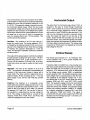
Horizontal Output
The signal from the horizontal output driver, 0101,
is
coupled to the base of
0102
through transformer
TX1
01.
0102
controls the current
in
the primary wind-
ing of horizontal output transformer TX102 to switch
scan current
in
yoke TX2028 for right-side scan. C118
and the yoke inductance provide a resonant retrace
pulse that resets the beam to the left side of the
screen. Diode CR102 then provides scan for the left
side of the screen. The current through the yoke estab-
lishes the magnetic field necessary to deflect the elec-
tron beam along a horizontal plane. The retrace pulse
is also fed to TX102 where it is stepped up to provide
high voltage for the CRT.
Vertical Sweep
The vertical circuit consists of:
1.
A 2-transistor, free-
running oscillator and
2.
An
IC
power amplifier with
retrace pulse generator.
Transistors 0301 and
0302
form a free-running oscil-
lator. Sync pulses injected into the junction of resistors
R302 and R303 lock the oscillator to the proper scan
frequency. A DC reference level, which is determined
by the voltage across resistor R306, is established
across capaCitor C303. The oscillator produces a saw-
tooth voltage which is superimposed
on
this DC level.
The amplitude of the sawtooth voltage and,
in
turn,
the vertical size of the CRT screen raster are set by
resistors R309 and
R311
and VERT SIZE control
R312. The sawtooth voltage is fed to the noninverting
input (pin 7) of power amplifier IC301. The amplified
signal then drives yoke TX202A. The parabola voltage
across yoke coupling capacitor CX306 is "S" -shaped
by a network consisting of resistors R317 and R316
and capacitors CX309 and CX307. This signal is
summed with the yoke current sample from R319 and
fed back into the inverting input (pin
1)
of IC301, pro-
viding linearity correction.
Circuit Description

IC301
also contains a flyback generator which retraces
the vertical scan current quickly without excessive
power penalty. It also provides vertical retrace blanking
from pin
3.
Spot Burn Protection
When the monitor is turned off, the filament of the CRT
is
still hot and capable of emitting electrons. With a
high potential still on the face of the CRT, it is possible
that a beam of electrons could be attracted to one
particular area of the screen. If this occurs, the phos-
phor
on
the screen may be burned, leaving a light spot
which
is
visible even after the filament has cooled and
no
current flow exists.
To
prevent spot burn, capacitor CX124 charges to ap-
proximately 60 volts while the monitor is in use. When
power is switched off, CX124 does not have a dis-
charge path because the collector of Q202 represents
a high impedance. The cathode of the CRT, pin
2,
is
therefore held positive, attracting the electrons from
the hot filament and preventing them from striking the
CRT. Diode CR108 is reverse biased, preventing
CX124 from discharging through
it.
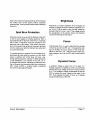
Circuit Description
Brightness
Adjustment of master brightness R142 changes the
amount of voltage across the external brightness con-
trol,
R143.
R143 is used to vary the bias voltage
on
the grid of the CRT, pins 1 and
5.
This voltage controls
the acceleration of the electron beam and therefore
controls the intensity of illumination.
Focus
Potentiometer
R141
is used to adjust the bias voltage
on
the final grid of the CRT, pin
7.
Changing this volt-
age will change the focus (clarity) of the raster dis-
played
on
the CRT. The + 500-volt power supply pro-
vides voltage to pin 6 of the CRT and to focus control
R141.
Dynamic Focus
A parabolic voltage is taken from C113 (yoke "S"-
shaping capacitor), amplified by Q103, and combined
with the
DC
focus voltage at the arm of focus control
R141.
This parabolic voltage compensates for the flat
CRT by raising the focus voltage at the sides of the
CRT,
thus keeping the beam
in
focus as it sweeps
across the entire face of the CRT.
Page
7

Servicing
This section provides servicing information to assist
in
servicing and troubleshooting the monitor. Included
are safety servicing guidelines, cleaning instructions,
adjustments, inspection, testing, and troubleshooting.
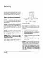
Safety and Service Guidelines
WARNING: No work should be attempted
on
any part
of the chassis by anyone not familiar with Zenith ser-
vice procedures and precautions. Otherwise, personal
injury may result.
WARNING: With the monitor power turned off and dis-
connected, discharge the high voltage anode lead at
the CRT using a jumper lead connected between the
chassis and a screwdriver (See Figure 14). Failure to
comply could result in severe shock and/or personal
injury.
WARNING: Do not operate a monitor with excessive
high voltage because the monitor will produce x-rays
from the CRT when the high voltage is excessive. Al-
ways verify that the high voltage
is
at the normal level
when servicing the unit.
WARNING: Handle the cathode-ray tube carefully
when you hold, remove, or install it. Otherwise, implo-
sion and/or injury may result.
NOTE: Under no circumstances should the original de-
sign be modified or altered without permission of
Zenith Electronics Corporation.
Page
8
A.C.
VOLTMETER
(5K
OHM/VOLT
MINIMUM)
I~I
22-4384
.15uF
AC
TVPE
II
rh
II
PLACE
THI
ROUND
63-10401-76
ON
EACH
PIPE,
TO
GOOD
EARTH
G
SUCH
AS
WATER
CONDUIT,
ETC.
S
PROBE
EXPOSED
PART.
MET
ALLIC
15000
10
WATT
Figure
3
AC
Leakage
Voltmeter
Circuit
AC LEAKAGE TEST
To prevent electrical shock after reassembly, perform
an
AC leakage test on all exposed metal parts of the
monitor.
Do
not use a line isolation transformer to per-
form this test.
1.
2.
Connect the test circuit as shown
in
Figure
3.
With monitor power turned on, measure the
leakage voltage between earth ground and
an
exposed monitor metal part.
3.
Repeat the measurement with the meter leads
reversed.
4.
Repeat steps 2 and 3 until all exposed monitor
metal parts are verified to have satisfactory AC
leakage levels.
WARNING: Any leakage voltage measurement that
exceeds 0.75 volts rms (0.5 milliamperes AC) consti-
tutes a potential shock hazard and must be corrected.
CAUTION: Some of the integrated circuits (ICs) used
in
the monitor are electrostatic-sensitive devices
(ESO). These devices can be damaged by static elec-
tricity. When handling any
IC,
use a wrist grounding
strap or be sure to equalize the static charge before
touching the
IC.

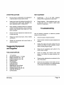
OTHER PRECAUTIONS
•
•
•
•
•
•
Be sure that all components are positioned in
a way that does not cause short circuits.
Inspect and correct all soldered connections for
cold solder jOints, frayed leads, damaged insu-
lation, splashed solder, or sharp points.
Never release a repaired product to a customer
unless all protective devices, such as insulators,
barriers, cover shields, strain reliefs, etc., have
been reinstalled.
Remove all loose material from inside the moni-
tor after servicing.
Follow the original lead layout, dress, lengths,
and tension.
Replace all components with exact Zenith re-
placement types.
Suggested Equipment
and Supplies
TOOLS AND SUPPLIES
•
1/4" nut driver
•
Standard screwdriver, 1/4" blade
•
Phillips screwdriver, No.1 tip
•
Phillips screwdriver,
No.2
tip
•
Diagonal cutters
•
Wire strippers
•
Long-nose pliers
•
Desoldering tool
•
Soldering iron, 25 to 40 watt
•
Solder, 60/40, HE-331-13
•
Desoldering braid, HE-490-185
•
Cable ties, HE-354-59
•
Lint-free cloths
Servicing
TEST EQUIPMENT
•
•
Oscilloscope - DC to 35 MHz, triggered
sweep, with low capacitance (3 pF) probe.
Digital voltmeter - High impedance input, zero
to 1000 volts, zero to 1 megohm, Heath model
SM-2215, or equivalent.
Troubleshooting
Use the following inspection to determine possible
causes of monitor failures.
•
•
•
•
•
•
•
Check for proper computer operation.
Check monitor controls for proper response and
settings.
Unplug the signal and power cables from the
monitor and check for burnt insulation, broken
wires, or loose prongs on plugs.
Check the AC receptacle (wall outlet) for the
proper supply voltage.
Check all cabling and internal circuit board
plugs
in
the monitor for proper electrical con-
nections.
Check monitor adjustments as explained at the
end of this section.
Check all circuit boards in the monitor for bro-
ken
or burnt components or for darkened areas
or other signs of component overheating.
Page 9

Table 1
General Troubleshooting
PROBLEM
Monitor completely dead.
No
video (Power Indicator
is
lit-High
and Low
voltages are OK).
Insufficient brightness.
No
raster.
Characters on screen
out of focus.
No horizontal sync.
Page
1.0
POSSIBLE CAUSE
1.
2.
3.
4.
5.
1.
2.
3.
Power cord not connected.
Power switch not on.
Fuse is missing or blown.
Power supply failure.
Shorted horizontal output.
Signal cable not connected
to computer.
Contrast control set to low.
CRT socket board defec-
tive.
4.
Main circuit board defec-
tive.
5.
6.
1.
2.
3.
1.
2.
3.
4.
1.
2.
3.
1.
2.
Wiring between boards de-
fective.
No
signal from the com-
puter.
Brightness control set to
low.
CRT socket board defec-
tive.
Main circuit board defec-
tive.
Brightness control defec-
tive.
Horizontal circuit/high volt-
age not working.
CRT socket board defec-
tive.
CRT defective.
Focus control defective.
CRT· socket board defec-
tive.
Main circuit board defec-
tive.
Horizontal hold control de-
fective.
Horizontal processor,
IC1
01
, defective.
Table 1 (contInued)
General Troubleshooting
PROBLEM
No vertical sync.
Vertical sweep scans
bottom
to
top.
Horizontal sweep scan
right
to
left.
POSSIBLE CAUSE
1.
2.
Table 2
Vertical size control defec-
tive.
Vertical processor
IC301
defective.
Red
and blue wires re-
versed on deflection yoke.
Yellow and black wires
re-
versed
on
deflection yoke.
Circuit Board Troubleshooting
PROBLEM
No
raster.
No
video (Raster OK).
No
vertical deflection.
No
vertical sync.
POSSIBLE CAUSE
1.
2.
3.
4.
5.
1.
2.
3.
4.
5.
1.
2.
3.
4.
0102, TX102 (check high
voltage at CRT anode.
CR102, RX133, RX136.
0101,0102,
TX101.
IC101.
VX201
CRT.
0201, 0202, 0204.
VX201, R402 Contrast
control.
CR103.
CRT socket.
Excessively high B + volt-
age.
High.8+
will cause
0206
to conduct, killing the
video signal.
0301,0302.
IC301.
TX202A, yoke.
CR301.
CR302, 0301, 0302,
R323, R326, C312, C316.
Servicing

Table 2 (continued)
Circuit Board Troubleshooting
PROBLEM
POSSIBLE CAUSE
Vertical sweep off frequency. IC301.
No
horizontal sync.
1.
0404
and circuit compo-
nents.
2.
IC101.
3.
R101
Horizontal Hold con-
trol, CX104.
Horizontal sync off frequency. 1. IC101.
Poor horizontal linearity 1.
TX102, LX101, LX102,
or foldover.
CR106.
2.
TX202B, yoke.
3.
0106,
0101, 0102.
Narrow horizontal raster.
1.
0102, TX101.
2.
LX102, CR106.
Characters out of focus.
1. CR107, RX136, C122.
2.
R141
Focus control.
3.
0103
and circuit compo-
nents.
Only top or bottom of
1.
IC301.
vertical deflection.
2. Vertical
deflection yoke
TX202A open.
No
high voltage on CRT.
1.
0106,0101,0102.
2.
Yoke TX202B winding
open.
3.
Flyback transformer
TX102.
4.
CR102.
No
video.
1-
0201, 0202, 0204,
l201
open.
2.
Signal cable defective.
Servicing
Adjustments
Use a computer to provide signals for the following
adjustments.
B+
(+16.2
V)
VOLTAGE
NOTE: This adjustment may interact with the focus
adjustment.
1.
Switch off the monitor power and disconnect it
from
facility power.
2.
Remove the back cover
and
reconnect the ca-
bles.
3.
Locate the B + adjustment, RX503 (See Figure
4).
4.
Connect a Heath SM-2215 or equivalent
DVM
between any B + point and chassis ground.
5.
Adjust the B + adjustment for + 16.2 volts.
FOCUS
NOTE: CRT yoke adjustment may interact with the
focus adjustment.
1.
2.
3.
4.
5.
Turn off the monitor power
and
disconnect it
from facility power.
Remove the back cover
and
reconnect the ca-
bles.
Locate the focus adjustment,
R141
(See Figure
4).
Set the contrast
and
brightness controls
to
nor-
mal levels with characters displayed.
Adjust the focus adjustment for the clearest,
sharpest display.
Page
11

CRT YOKE
NOTES:
1.
2.
3.
These adjustments may interact with the focus
adjustment.
Do
not overtighten the yoke clamp.
Make sure the yoke is positioned as far forward
on
the CRT as possible. If necessary, unclamp
the yoke; then slide it forward, and reclamp.
Positioning
1.
2.
Loosen the clamp screw and rotate the deflec-
tion yoke until the edges of the display are
parallel with the edges of the screen; then
tighten the clamp screw.
Adjust the centering rings so that the display
is centered on the screen.
Linearity
1.
2.
3.
Remove the ferrite foam magnets that may be
installed
on
the yoke.
Select the most nonlinear of the four displayed
edges and install a ferrite magnet
on
the yoke
post nearest the greatest distortion.
Repeat step 2 as necessary, around the yoke,
until a uniform rectangular shape is displayed.
NOTE: If only a small change
in
linearity is needed,
reduce the size of the ferrite magnets by cutting off
a small portion with diagonal cutters.
Page 12
Cleaning Procedures
WARNING: Be sure that the monitor's power cable
is unplugged before you clean the monitor.
•
Clean the cabinet with a lint-free cloth, mildly
dampened with a nondetergent cleaning solu-
tion; do not spray liquids directly on the monitor
or use a wet, saturated cloth.
• Clean dust from the monitor's screen with a lint-
free cloth.
•
•
Clean heavy dirt from the monitor's screen with
a swab soaked with isopropyl alcohol.
Be sure the monitor is completely dry before
applying electrical power.
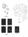
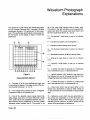
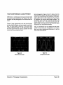
Servicing Diagrams
Component location drawings, waveform photographs,
and schematic diagrams are provided along with Table
3,
B + Supply Transistor Voltages.
The circuit location of each waveform is indicated
on
both the schematic and the component location draw-
ing. A Z -160
PC
Series computer with color bar output
was used to supply signals for generating the
waveforms. Refer to "Waveform Photograph Explana-
tions" at the back of the manual.
Servicing

B+(+
16.2Vdc)~
ADJUST
Servicing
-f+---
CfllI501
---c;(jJ
Figure
4
Main
Board
Component
Location
FOCUS
ADJUST
MASTER
BRIGHTNESS
ADJUST
IC30
1
PIN
5
(RED
LEAD
AT
YOKE)
Page 13
IC30
1
PIN
3
(CX311
NEGATIVE
TERMINAL)
0101
COLLECTOR
(R119)
IC
101,PIN
1
0102
COLLECTOR
Figure 5
Main Board Waveforms
">06
'"
r-----~-~--!-li
~:_~ri
i...r~5YL
Ie
301
1'1302
'"
''1303
no..:
1'1304
"
I/'IW
, I
,,%
IoIORI2
R'f~
!:!2!:E...
"'"
'"
1'11111
cl061
1.2'"
opT
-=
P0lY-=-
.,
RI37
RI24
'r'JOK
V£RT
INPUT
1'1104
'"
,%
1
1
,;.:l;'[
,
101(
Ie
I
01
'---j----
fill3
CI01
l-
~-
1
---t
I--~
"0'
[J
;~ot_c'~i'_~"'_",_,'_·_'
L:~=:~=~~======
0103
BASE
0103
.-
.J',l
Io,;,~
I'
I
-------f--1i
+ '
---------<r------ti-"2"~'
-t
1--
~g
1-
,1-,
i,,,I~":J
JI i
l
_________________
J
~I~~l~
I
+~~~')
- I
MAIN
BOAi'EJ
CRT
BOARD
1,,,1
C406
To022
I
I
~
I~~
~
'09
T''':;'''l
I
_-1
Q203
I;Z02
1.61(
@
~"'"
L201
8.%
..
"
____
c:..~T
B~~'!t:J_c"
BOARD
"
1
RI~O
2201(
'U3.
"""
lit.
"
...
"
>TO,
",.
"
..
""'"
112W
RI41
Icf.::,t/2W
".,
,.
fOCUS
::6~
j
RII"
: 1'1144
r----;:=~=~=;:*~::-!
rFA~~SAFE
-I
I i
tRI02
T i T.,ole . ' I
AX'"
' ,
t-L~IA~
L~·9
NOTE:
'"
~%:&k'
•..
1.
CRITICAL
SAFETY
COMPONENTS
Clts
4TO"'D
,,~
THE
LETTER
·X·
IN
THE
ELECTRICAL
SCHEMATIC
AND
PARTS
LIST
DESIGNATES
SPECIAL
SAFETY
CRITICAL
COMPONENTS.
THESE
SHOULD
BE
RE-
PLACED
ONLY
WITH
TYPES
IDENTICAL
TO
THOSE
IN
THE
ZENITH
PARTS
LIST
AND
SCHEMATIC.
~
REFER
TO
FIGURE
9
FOR
ZVM-124Q
B+
SUPPLY
SCHEMATIC.
REFER
TO
FIGURE
10
FOR
ZVM-1240-E
B+
SUPPLY
SCHEMATIC.
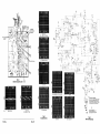
Figure 6
ZVM-1240/1240-E Schematic

Figure 7
REGULATOR
BOARD
(ZVM-1240-E
ONLY)
B + Supply Component Location
Figure 8
Waveform - Anode
of
CRX506
,_.
wm'~4:TE--~
---
-
---
-
--
-
----
I
L~
BLACK
fX501
CR)(502
I
I
________
---.J
~
-
t2ZW2£
CHASSIS ONLY I
I
F)(?OI
(EARLY
MONITORS)
, ,
I'ROW'
mo,
I
lJ
'
~w,
~
I
120VAC i
6£
H_'
______
--.J
Figure 9
B
+ Supply Schematic - ZVM-1240
Page 14
I
I
I
TRANSISTOR
LOCATION
QXso
1
QXS02
QXS03
QXS04
B
-2.00
+22.4S
+.616
+2.41
E
0.00
+23.07
+20.20
+2.90
C
+1S7.6
+
16.20
+00.02
+0.616
B+16.2VDC
(B+
WITH
FULL
CONTRAST
&
BRIGHTNESS=+
16.06)
(8+
WITH
MINIMUM
CONTRAST
&
8RIGHTNESS=+
16.23)
lable3
B + Supply Transistor Voltages
---
-
---
-
-----;
L
__
I
I
~H'
L
'
POWER
ON
I 'tV
ZI
::~~'l---w~""H':';;;::U
I
INDle
...
TOft
-----
,
________
-.
___
.
___
'
._-_
..
_____
.
__
---.J
Figure 10
B
+ Supply Schematic - ZVM-1240-E
Servicing

CRT
SOCKET
.~
7
CRT
SOCKET
PIN
ASSIGNMENTS
(LOOKING
FROM
THE
FOIL
~~'
" CRTSIDE
OF
THE
CRT
BOARD)
\.
".'
SOCtKTET
/
;i!JRO
Figure
11
CRT Board Component Location
0203
BASE
0201
BASE
Figure 12
CRT Board Waveforms
"~O2
Page 15
9
'"
,,~
I , •
C~3OI
"~O4
cr"'-"
'0%
®
AC
COUPLED
0204
COLLECTOR
(+15.53VDC)
SEE
FIGURES
9
AND
10
FOR
Bt(+16.2VDC)
SUPPLY
SCHEMATICS
Figure 13
CRT Board Schematic
"'~I
.
~
.~
I/IW
.M
•
.ro.
,nw
""
_.
1/2_
CRT
CII.
410"~O
".

iO
CIRCUIT
BOARD
GROUND
~-
-----.
CAREFULL
Y
SLIDE
A
GROUNDED
FLAT
SCREWDRIVER
TIP
UNDER
THE
LIP
OF
THE
ANODE
LEAD.
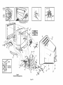
Figure
14
ZVM-1240/1240·E
Exploded
View
WARNING
DISCHARGE HIGH
VOLTAGE BEFORE
ATTEMPTING
LEAD
REMOVAL
Page
16
MAGNET~
I
YOKE
CLAMP
.4l~~~
SCREW
~:.......
~
--_
135
'-
--
Page is loading ...
Page is loading ...
Page is loading ...
Page is loading ...
Page is loading ...
Page is loading ...
Page is loading ...
Page is loading ...
Page is loading ...
Page is loading ...
-
 1
1
-
 2
2
-
 3
3
-
 4
4
-
 5
5
-
 6
6
-
 7
7
-
 8
8
-
 9
9
-
 10
10
-
 11
11
-
 12
12
-
 13
13
-
 14
14
-
 15
15
-
 16
16
-
 17
17
-
 18
18
-
 19
19
-
 20
20
-
 21
21
-
 22
22
-
 23
23
-
 24
24
-
 25
25
-
 26
26
-
 27
27
-
 28
28
-
 29
29
-
 30
30


Zenith ZVM-1240-EM User manual
- Type
- User manual
- This manual is also suitable for
Ask a question and I''ll find the answer in the document
Finding information in a document is now easier with AI
Related papers
Other documents
-
Schonbek 1240-26S Operating instructions
-
Elenco EP130 Owner's manual
-
Sony KDP-65WS550 User manual
-
Texas Instruments AN-1013 Video Amplifier Design for Computer Monitors Application notes
-
Apple 1705 User manual
-
-
Compaq MV7540 User manual
-
 Remotec ZDS-210NA User manual
-
Motorola 14T3 User manual
-
Crown D-Series User manual
