Page is loading ...

Drill Press Milling Vise
Item 94276
Read this material before using this product.
Failure to do so can result in serious injury.
SAVE THIS MANUAL.
When unpacking, make sure that the product is intact and undamaged.
If any parts are missing or broken, please call 1-800-444-3353 as soon as possible.
Visit our website at: http://www.harborfreight.com
Email our technical support at: [email protected]
Copyright
©
2006 by Harbor Freight Tools
®
. All rights reserved. No portion of this manual or any artwork contained herein may be reproduced in any
shape or form without the express written consent of Harbor Freight Tools. Diagrams within this manual may not be drawn proportionally.
Due to continuing improvements, actual product may differ slightly from the product described herein.
Tools required for assembly and service may not be included.
Revised Manual 11f

SKU 94276 For technical questions please call 1-800-444-3353. Page 2
SPECIFICATIONS
SAVE THIS MANUAL
You will need the manual for the safety warnings and precautions, operating
and maintenance procedures, parts list and diagram. Keep your invoice with
this manual. Write the invoice number on the inside of the front cover. Keep
the manual and invoice in a safe and dry place for future reference.
SAFETY WARNINGS AND PRECAUTIONS
1. KEEP PRODUCT USAGE AREA CLEAN. Cluttered areas invite injuries.
2. KEEP CHILDREN AWAY FROM PRODUCT USAGE AREA.
Do not allow children to handle this product.
3. DO NOT USE THIS PRODUCT IF UNDER THE INFLUENCE OF ALCOHOL
OR DRUGS. Read warning labels on prescriptions to determine if judgement or
reexes are impaired while taking drugs. If there is doubt, do not use this product.
4. USE EYE PROTECTION. Wear ANSI-approved safety impact goggles. Use
respiratory mask to cover nose and mouth if working with dusty material. Avoid
dangerous environments. Goggles are available from Harbor Freight Tools.
5. DRESS SAFELY. Do not wear loose clothing or jewelry as they can
become caught in moving parts. Wear a protective hair covering to
prevent long hair from becoming caught in the moving parts.
6. DO NOT OVERREACH. Keep proper footing and balance at all times.
7. STAY ALERT. Watch what you are doing at all times. Use common sense.
Do not operate this product when you are tired or distracted from the job at hand.
8. CHECK FOR DAMAGED PARTS. Before using this product, carefully
check that it will operate properly and perform its intended function.
Check for damaged parts and any other conditions that may affect its
operation. Replace or repair damaged or worn parts immediately.
9. DO NOT USE POWER TOOLS IN DAMP OR WET AREAS.
Use common sense when working with power tools.
ITEM DESCRIPTION
Tool Dimensions 7 IN. X 8-1/2 IN. X 5-5/8 IN. High (Overall Base Dimensions)
Maximum Jaw Opening 4-3/4 IN.
Cross Travel 6 IN.
Jaw Depth 1-1/4 IN.
Longitudinal Travel 6-1/4 IN.
Features 56 Square Inch X and Y Movement Calibrated to Scales
REV 06l; 11f

SKU 94276 For technical questions please call 1-800-444-3353. Page 3
10. MAINTAIN PRODUCT WITH CARE. Keep this product clean and dry,
and moving parts lightly lubricated for better performance. Keep the
Handle dry, clean and free from oil, grease, and solvents.
11. USE THE RIGHT PRODUCT FOR THE RIGHT JOB. Do not attempt to force
a small tool or attachment to do the work of a larger industrial tool. There are
certain applications for which this tool was designed. It will do the job better
and more safely at the rate for which it was intended. Do not modify this tool
and do not use this tool for any purpose other than which it was intended.
12. MOUNT THIS ITEM SECURELY BEFORE USE. The forces exerted on this
vise during use may cause a poorly mounted or unmounted vise or workpiece
to come loose; causing SEVERE PERSONAL INJURY or property damage.
13. CAREFULLY FOLLOW ALL WARNINGS AND OPERATION INSTRUCTIONS,
INCLUDING ACCESSORY MOUNTING INSTRUCTIONS, PROVIDED
WITH THE EQUIPMENT YOU WILL MOUNT THIS VISE ON.
14. MAKE SURE THAT THE EQUIPMENT’S BIT DOES NOT COME IN
CONTACT WITH THIS VISE. Damage to the vise may damage the
workpiece or cause a piece to y off causing personal injury.
INSTALLATION
1. Make sure the power-head of your drill press is fastened securely to
the column of the drill press. Lock the worktable into place.
2. Secure the mount base of the Vise in the center of the drill press worktable, using
appropriate hardware, as provided with or explained in the manual for the milling/drilling
machine (hardware not included). Make sure that the hardware used solidly secures
the vise and does not interfere with the X/Y adjustment of the vise. See Figure 1.
Figure 1
Vise Base

SKU 94276 For technical questions please call 1-800-444-3353. Page 4
OPERATION
All parts below refer to the parts listed on page 8 of this manual.
1. The Adjustment Screw (8) and Middle Base Screw (10) are for adjusting the tension
on X/Y movement. Use the thumbscrews to hold the Adjustment Screws (8 & 10)
at the desired tension. See Figure 2 and Parts Diagram, page 7.
Adjustment
Screw (8)
Figure 2
Middle Base
Screw (10)
2. Turn the Thumb Screw eight turns per inch (1/8” per turn). Match up with the visual aid
reference scales (SAE) which are located on all four sides of the Vise.
See Figures 3 & 4.
Visual Aid
Reference
Scales
Figure 3
Thumb
Screw
Figure 4
Thumb
Screw

SKU 94276 For technical questions please call 1-800-444-3353. Page 5
3. Vertical slack (slop) adjustment is done by loosening the Hex Screws.
The Small Jaw (4) will slide down and ride against the mill rail of
the Upper Base (18). Retighten Screws. See Figure 5.
Hex Screws
Small Jaw
(4)
Figure 5
Mill Rail of Upper
Base (18)
4. The opposing adjustable jaws enable the work piece to be rmly
secured yet located in the middle of the X/Y movement.

SKU 94276 For technical questions please call 1-800-444-3353. Page 6
MAINTENANCE
1. Keep the moving parts oiled, being sure to wipe off any
excess oil off of the Handle and Jaws.
2. Keep the Jaws clean so your workpiece will not be soiled.
3. Check and tighten the screws to be sure the Vise is secure.
4. Replacing a Jaw:
To replace a Jaw, use a Phillips Head Screwdriver (not included). Unscrew
the Screws and set aside. Replace with new Jaw and replace Screws.
Tighten. Repeat on the other Jaws if necessary. See Figure 6.
Figure 6
Jaw Plate (2)

SKU 94276 For technical questions please call 1-800-444-3353. Page 7
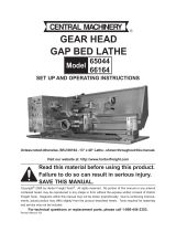
Parts Diagram
Note: Some parts may be listed and
shown for illustration purposes only and
are not available as replacement parts.

SKU 94276 For technical questions please call 1-800-444-3353. Page 8
PARTS LIST
Part Description Qty Part Description Qty
1 Bottom Base 1 11 Retainer Plate 2
2 Jaw Plate 6 12 Spring Washer 1/4” 4
3 Flat Head Screw 1/4”-20 x 1/2” L 12 13 Hex Screw 1/4”-20 x 5/8” L 4
4 Small Jaw 4 14 Middle Base 1
5 Bracket 6 15 Rule 4
6 Flat Head Screw 1/4”-20 x 3/8” L 8 16 Rivet 2 x 5L 8
7 Flat Head Screw 1/4”-20 x 7/8” L 4 17 Upper Base Screw 1
8 Jaw Adjustment Screw 3 18 Upper Base 1
9 Nut Block 2 19 Jaw Screw 1
10 Middle Base Screw 1
PLEASE READ THE FOLLOWING CAREFULLY
THE MANUFACTURER AND/OR DISTRIBUTOR HAS PROVIDED THE PARTS DIAGRAM IN THIS MANUAL
AS A REFERENCE TOOL ONLY. NEITHER THE MANUFACTURER NOR DISTRIBUTOR MAKES ANY
REPRESENTATION OR WARRANTY OF ANY KIND TO THE BUYER THAT HE OR SHE IS QUALIFIED TO MAKE
ANY REPAIRS TO THE PRODUCT OR THAT HE OR SHE IS QUALIFIED TO REPLACE ANY PARTS OF THE
PRODUCT. IN FACT, THE MANUFACTURER AND/OR DISTRIBUTOR EXPRESSLY STATES THAT ALL REPAIRS
AND PARTS REPLACEMENTS SHOULD BE UNDERTAKEN BY CERTIFIED AND LICENSED TECHNICIANS
AND NOT BY THE BUYER. THE BUYER ASSUMES ALL RISK AND LIABILITY ARISING OUT OF HIS OR HER
REPAIRS TO THE ORIGINAL PRODUCT OR REPLACEMENT PARTS THERETO, OR ARISING OUT OF HIS OR
HER INSTALLATION OF REPLACEMENT PARTS THERETO.
90 Day Warranty
Harbor Freight Tools Co. makes every effort to assure that its products meet high quality and durability
standards, and warrants to the original purchaser that this product is free from defects in materials
and workmanship for the period of 90 days from the date of purchase. This warranty does not apply to
damage due directly or indirectly, to misuse, abuse, negligence or accidents, repairs or alterations outside
our facilities, criminal activity, improper installation, normal wear and tear, or to lack of maintenance.
We shall in no event be liable for death, injuries to persons or property, or for incidental, contingent,
special or consequential damages arising from the use of our product. Some states do not allow the
exclusion or limitation of incidental or consequential damages, so the above limitation of exclusion
may not apply to you. THIS WARRANTY IS EXPRESSLY IN LIEU OF ALL OTHER WARRANTIES,
EXPRESS OR IMPLIED, INCLUDING THE WARRANTIES OF MERCHANTABILITY AND FITNESS.
To take advantage of this warranty, the product or part must be returned to us with transportation charges
prepaid. Proof of purchase date and an explanation of the complaint must accompany the merchandise.
If our inspection veries the defect, we will either repair or replace the product at our election or we may
elect to refund the purchase price if we cannot readily and quickly provide you with a replacement. We will
return repaired products at our expense, but if we determine there is no defect, or that the defect resulted
from causes not within the scope of our warranty, then you must bear the cost of returning the product.
This warranty gives you specic legal rights and you may also have other rights which vary from state to state.
3491 Mission Oaks Blvd. • PO Box 6009 • Camarillo, CA 93011 • (800) 444-3353
/