Page is loading ...

INSTALLATION MANUAL
SONANCE OPTILINQ
2 IR REPEATER KIT over CAT5
USB POWER ADAPTOR
Introduction
Sonance IR products provide a simple solution to
controlling multiple AV devices. The IR Receivers pick up
commands from an infrared remote control and send
them to one or multiple points to be re-transmitted
through an IR Emitter. This system allows electronic
components to be hidden in cupboards or mounted
remotely in a rack while still providing a reliable means
of controlling them locally from a single point.
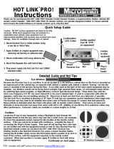
Box Contents
(1) Dual IR Emitter, (2) IR Covers, (1) AC Power Supply
with USB Adaptor Cable, (2) Emitter TX/RX Connection
Blocks with Cat5 Inputs, (3) Adhesive strips with IR
Emitter holes, and (1) Dual Band Receiver.
Specifications
Compatible with all brands of A/V devices
Output frequency:30-60 (kHz)
Receiving Distance: 40’- 50’ (12-15 m)
Two choices for power included, AC or USB
Max cat5e/6 distance 700ft (213m)
Cat5e/6 cable not included
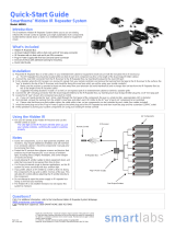
TX/RX Block (bidirectional communication)
1. Power connection, two options (12V,1A)
a) AC power; best extension up to
700 ft.(214 m).
b) USB, for standard IR protocol, detachable
plug/cord up to 330 ft. (100 m)
c) USB, Boxes that have short time IR
protocol cycles like, RCMM (ATT Uverse)
and FoxTel boxes, the range is half the
standard protocol at 165 ft. (50 m)
2 Local IR emitter output, for single or dual emitters
3 Dual Band receiver module with 3.5mm connector
4 Cat5e/Cat6 output to connect to TX/RX POE, power
over ethernet, no need for additional power source for TX/RX
5 Remote IR emitter output, for single or dual emitters
Emitter TX/RX
Connection Blocks
AC Power Supply USB Power Supply Dual Band Receiver
Adhesive Strips
with Emitter holes
IR Covers
USB power cord
OR optional AC Power
Emitter output for local components
(not included)
Dual Band receiver module
with 3.5mm connector
Cat5e or Cat6 network cable from up to
700 ft. (214 m) AC power, and 330 ft. (100 m) for USB
CAT5e/6
IR IN
PWRIR OUT
CAT5e/6
Dual IR Emitter
4
3
1
2
Dual IR Emitter
Emitter output for remote components
4
IR OUT
IR IN
PWR
1
3
5
Optional position for
USB power cord
OR optional AC Power
(only power one side
of repeater system)
Emitter Installation
Place the IR Emitter directly over the IR sensor located
in the front panel colored window. You can locate it
by looking up the front panel of the cable box user
guide or use a flashlight to locate the sensor. It will
look square. Place the Receiver Eye on or near your TV
or flat screen
Notes
Extra adhesive strips with 1/16” hole included to
prevent IR sensor flooding on the device
Keep twist ties to wrap excess cables

LIMITED WARRANTY
Sonance warrants to the first end-user purchaser that this
Sonance-brand product (“Product”), when purchased from
an authorized Sonance Dealer/Distributor, will be free from
defective workmanship and materials for two (2) years.
Sonance will at its option and expense either repair the defect
or replace the Product with a new or remanufactured Product
or a reasonable equivalent.
EXCLUSIONS
TO THE EXTENT PERMITTED BY LAW, THE WARRANTY SET
FORTH ABOVE IS IN LIEU OF, AND EXCLUSIVE OF, ALL OTHER
WARRANTIES, EXPRESS OR IMPLIED, AND IS THE SOLE AND
EXCLUSIVE WARRANTY PROVIDED BY SONANCE. ALL OTHER
EXPRESS AND IMPLIED WARRANTIES, INCLUDING THE
IMPLIED WARRANTIES OF MERCHANTABILITY, IMPLIED
WARRANTY OF FITNESS FOR USE, AND IMPLIED
WARRANTY OF FITNESS FOR A PARTICULAR PURPOSE
ARE SPECIFICALLY EXCLUDED. No one is authorized to
make or modify any warranties on behalf of Sonance.
The warranty stated above is the sole and exclusive remedy
and Sonance’s performance shall constitute full and final
satisfaction of all obligations, liabilities and claims with
respect to the Product. IN ANY EVENT, SONANCE SHALL
NOT BE LIABLE FOR CONSEQUENTIAL, INCIDENTAL,
ECONOMIC, PROPERTY, BODILY INJURY, OR PERSONAL
INJURY DAMAGES ARISING FROM THE PRODUCT, ANY
BREACH OF THIS WARRANTY OR OTHERWISE.
This warranty statement gives you specific legal rights, and you
may have other rights which vary from state to state. Some
states do not allow the exclusion of implied warranties
or limitations of remedies, so the above exclusions and
limitations may not apply. If your state does not allow
disclaimer of implied warranties, the duration of such implied
warranties is limited to period of Sonance’s express warranty.
Your Product Model and Description:
OPTILINQ 2 IR/CAT KIT
2 IR Repeater over Cat5 Kit
and USB Adaptor
Additional Limitations and Exclusions from Warranty Coverage:
The warranty described above is non-transferable, applies
only to the initial installation of the Product, does not include
installation of any repaired or replaced Product, does not
include damage to allied or associated equipment which may
result for any reason from use with this Product, and does not
include labor or parts caused by accident, disaster, negligence,
improper installation, misuse (e.g. excessive heat or cold or
humidity, outdoor installation), or from service or repair which
has not been authorized by Sonance.
Obtaining Authorized Service: To qualify for the warranty,
you must contact your authorized Sonance Dealer/Installer
or call Sonance Customer Service at (949) 492-7777, must
obtain a return merchandise number (RMA), and must deliver
the Product to Sonance shipping prepaid during the warranty
period, together with the original sales receipt, or invoice or
other satisfactory proof of purchase.
©2016 Sonance. All rights reserved.
Sonance is a registered trademark of Dana Innovations.
Due to continuous product improvement, all features and
specifications are subject to change without notice.
For the latest Sonance product specification information visit
our website: www.sonance.com
SONANCE • 991 Calle Amanecer
San Clemente, CA 92673 USA
(949) 492-7777 • FAX: (949) 361-5151 •
Technical Support: (949) 492-7777
www.sonance.com
Wiring Diagrams for Cat5, 5e,
6, 6a Cables
1. For Patch Cables, 568B wiring is by far the most
common method.
2. There is no difference in connectivity between
568B and 568A. Either wiring will work fine on
any system.
3. Ensure both ends are wired identical.
4. Do not confuse pair numbers with pin numbers. A
pair number is used for reference only (there are
four color coded twisted pairs in an 8 conductor
Category 5 or 6 cable). The pin number indicates
actual physical locations on the plug
(RJ45 connector) and jack
Trouble Shooting
Device does not respond to remote control
1. Check to see if the LED on the power supply is on
when plugged in.
2. Check to see if the receiver flashes when remote
keys are pressed
3. Check to see the if the receiver wire is
tightly connected
4. Make sure the remote batteries are new. Do not
mix old and new batteries
5. Make sure the cat5e/6 cables are securely
connected to each TX/RX block
6. Check to see the IR emitters flash when the IR
signal is transmitted
7. Check to see the IR emitters wires are
firmly connected
8. Make sure the emitter is placed directly on top
of the IR sensor located on the front panel of the
cable box or device. You can locate the sensor
by using a flashlight. It is located behind the front
panel bezel and will look square. You can also look
up your user guide on-line by typing in the make
and model number followed by user guide.
/