Page is loading ...

1
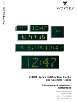
Model WST Programmable Timer
KEYBOARD FUNCTIONS:
Key Marking Function
S1 PROG Program Setting enabled.
S2 INCREMENT Increments the flashing number
S3 DECREMENT Decrement the flashing number
S4 MUTE/CLEAR Clear flashing digit
S5 TIMER Clock setting enabled
PROGRAMMABLE
TIMER
RELAY
PROG
TIM
ER
CLEA
R
HOLD
MUTE
ON
LOCK
1
2
D1
D2
D3
D4
D5
D6

2
S6 PREV Go to previous setting
S7 NEXT Go to next setting
S8 HOLDS Switch “off” relay manually
Relay on Indicator Lamps : These LED lamps glow, when the respective relay is
energized.
* Relay will not operate if Timer is in “Hold” mode.

3
Display Modes :
MODE
DIGIT (LEFT TO RIGHT)
D1
D2
D3
D4
D5
D6
1
DAY
HOURS
MINUTES
2
YEAR
DAY
MONTH
HOURS
DATE
MINUTES
3
HOURS
MINUTES
SECONDS
Mode 1 : This is normal mode. “ Day, Hours : Minutes” are displayed. Method of
returning to this mode is described below.
Mode 2 : “Hours : Minutes” and the “Year : Month : Date” flash alternately the display
reads “Hours : Minutes” for about 10 seconds and “Year : Month : Date” for a second.
To set this mode, ensure that the display is in the normal mode. Push S7, Keeping
“S7” pushed press “S2” to select the data as given below.
DATA Function
12 Slave output in 12 Hours format
12A Slave output in 12 Hours format + Time/ Date alternate
flashing
24 Slave out in 24 Hour format
24A Slave output in 24 Hours + Time / Date alternate
flashing.
Mode 3 : Push S4 for about 2 seconds. Hours. Minutes. Seconds are displayed. To
get back to the previous mode, press S4 for about 2 seconds.
Slave Display :The real time data is provided for driving model “WSS” salve
display units. To connect these, a socket marked “Serial Output” is provided on the
back side. Read troubleshooting before installing slave display.

4
Setting the time :
Push “S5” till all digits start flashing. This is the time setting mode. It allows the user to
set the Year , Month, date, day, Hours and Minutes As an example, let us set “1998
May 16, Tuesday, 2.30 P.M.”
Year : Press S7. D1 & D2 flashes showing a number from 0 to 99. Press S2 or S3 to
set the current year.
Month : Press S7. D3 & D4 flash showing a number from 1 to 12. Press S2 or S3 to set
the month to “5” for May.
Date : Press S7. D5 & D6 flash showing a number from 1 to 31. Press S2 or S3 to set
the date ‘22
nd’
May.
Day : Press S7. D1 flashes. Press S2 or S3 to set the current day of the week as a
number from 1 for Monday. 2 for Tuesday and so on up to 7 for Sunday. Set the day
to “2” for Tuesday.
Hours : press S7. D3 & D4 flash. Press S2 or S3 to set the Hours in the 24 Hour
Format, From 0 to 23. Set the hours to “14” for 2 PM.
Minutes : press S7. D5 & D6 flash. Press S2 or S3 to set the mintes from o to 59. Set
the minutes to “30”.
* Press S6 to go to previous setting.
If the unit is left in setting mode for more than three minutes, the display returns to the
normal mode automatically. If any changes were made, they are not registered.
Resetting the Seconds : Push S5. All digits flash. Push S5 once again. Seconds are
resets to “00”, without changing any other setting . This is useful for synchronizing the
timer with a known “standard” time.
Programming the Timer :
Sixty Four programs can be stored. Step by step procedure for setting or editing a
program is given in this section. Using the programming chart. Make a note of the
program (s) to be entered, modified, activated or de-activated. Keep this note handy
while you follow the steps (1) to (9) Below.

5
Ensure that the timer is in the normal display mode. (It is not in the time setting mode).
As soon as you enter programming mode in switch should be provided for each relay, if
you want to keep the respective output ON, while programming.
1. Push S1. D1 shows “P” and D2 flashes, Set D2 using S2 or S3 to select the desired
program . P flashes (01 to 64)
If D3 to D6 show ‘------ ‘ it means that the program is de-activated. Activating the
program is explained in (9). To examine or modify the program settings, go through
steps (2) to (8). Press S7 or S6.
2) Now, D1 shows “d” and D2 flashes, Use S2, S3, to set D2 for selecting the Day(s)
for operation :
D2 Day (s) of operation
0 Every day
1 Every Monday
2 Every Tuesday
3 Every Wednesday
4 Every Thursday
5 Every Friday
6 Every Saturday
7 Every Sunday
8 Every day except Monday
9 Every day except Tuesday
A Every day except Wednesday
B Every day except Thursday
C Every day except Friday
D Every day except Saturday
E Every day except Sunday
F Every day except Saturday & Sunday
After setting the day (s) of operation, press S7.

6
3) D1 now indicates “ r ”. D2 flashed to indicate the output type.
D2 Output type
1 Relay 1 Continuous
2 Relay 2 Continuous
3 Relay 1 and Buzzer
4 Relay 2 and Buzzer
5 Buzzer
6 Relay 1 interrupted
7 Relay 2 interrupted
use S2 and S3 to select the desire output type. Press S7.
4) D3, D4, flash, Use S2 or S3 to set the “Hours” to the time at which the output
should operate, press S7.
5) D5, D6 flash, use S2 or S3 to set the “minutes” to the time at which the output
should operate. Press S7.
6) D1 flashes a symbol a symbol “o” or “h” . This identifies the “ON duration range for
the output is user selectable.
D1 D2 D3 D4 D5 D6
O * -- Hr ------ ------ Mt ---- Time at which the output will cut-off
h * --- Mt --- -------- Sec ----- ON duration of the output (Max. 59M
59S)
* is 1 to 7 (indicates the output type selected in {3} above)
use S2 to select “o” or “h”. Press S7.
(7) D3, D4 flash. Use S2 or S3 to set the “Hours ” if the choice in (6) is “o”. If “h” was
chosen in (6) then you are setting the “Minutes” Press S7.
(8) D5, D6 flash. Use S2 or S3 to set the “Minutes” if the choice in (6) is “o”. If “h” was
chosen in (6) then you are setting the “Seconds” Press S7.
(9) The display returns to the condition in (1). “-----“ at D3 to D6 means that the
program is de-activated. To activate the program, push S1. Immediately , D3 to D6
will display the time set in steps (4) & (5) above. To de-activate the program, push
S4.
At this stage, you may change the program number to store or edit more programs or
press S5 to return to the normal mode.

7
Samples Programs
Ensure that the timer is in the normal display mode before trying any of the examples
below.
Ex. 1 : Set program no. “03”, to operate Relay -1 & buzzer at 7:15 AM for the period of
15 seconds on every day except Sunday.
1) Push S1, D1 and D2 flashes. Set D1, D2 to “03”using S2 or S3. Press S4 to de-
activate the program so that D3 to D6 read “ ------“. Press S7.
2) Now, D1 shows “d” and D2 flashes. Using S2 or S3 set D2 to “E” for selecting the
operation Days as “every day except Sunday”. Press S7.
3) D1 now indicates “r”. Using S2 or S3 set D2 to “3” for selecting Relay 1 as the
desired output. Press S7.
4) D3, D4 flash. Use S2 or S3 to set the “Hours” to “7” Press S7.
5) D5, D6 flash. Use S2 or S3 to set the “Minutes” to “15”. Press S7.
6) D1 flashed a symbol “o” or “h”. As the desired ON duration is less than an hour, use
S2 or S3 to select “h”. Press S7.
7) D3, D4 flash. Use S2 or S3 to set the “MINUTES” to “00”. Press S7
8) D5, D6 flash. Use S2 or S3 to set the “SECONDS” to “15”. Press S7.
9) The display returns to the condition in (1). Press S1 to activate the program. D3 to
D4 will read 7.15. Press S5.
Ex. 2 : Set program no. “64” , to operate Relay -1 (interupt operation) at 8.30 AM for
20 seconds every day.
1) Push S1. D1 and D2 flashes. Set d1, d2 to “64” using S2 or S3. Press S4 to de-
activate the program so that D3 to D6 read “--------“. Press S7.
2) Now, D1 shows “d” and D2 flashes. Using S2 or S3 set D2 to “o” for selecting the
operation Days as “every day “. Press S7.
3) D1 now indicates “r”. Using S2 or S3 set D2 to “6” for selecting “Relay 1 (interupted)
and buzzer” as the desired output. Press S7.
4) D3, D4 flash. Use S2 or S3 to set the “Hours: to “8” press. S7.
5) D5, D6 flash, Use S2 or S3 to set the “Minutes” to “30”. Press S7.
6) D1 flashes a symbol “o” or “h”. As the desired ON duration is less than an hour, use
S2 or S3 to select “h”. Press S7.
7) D3, D4 flash. Use S2 or S3 to set the “Minutes” to “00” Press S7.
8) D5, D6 flash. Use S2 or S3 to set the “Seconds” to “12” Press S7.
9) The display returns to the condition in (1). Press S1 to activate the program. D3 to
D4 will read 17.30. Press S5.

8
Ex. 3 : De-activate program no. 3 stored in Ex. 1 above. This is accomplished in just
one step.
1) Push S1. D1 and D2 flashes. Set D1, D2 to “03” using S2 or S3, D3 to D6 show
7.15. Press S4. D3 to D6 reads “--------“. Press S5.
TOUBLESHOOTING
The following will help users to overcome minor problems with the timer or slave
display. Before calling ION, Please check the “Faults & remedies” listed below.
Display shows freak readings. : If in normal mode, carry out the time setting
procedure. If in program mode, use S7 to make the freak digit (s) flash and then press
S4.
Relay do not operate as per a particular program. : Select that program in the program
setting mode and check if the decimal point of D6 is ON.
Relays operates when it is not expected to. Press S1 to enter program setting mode
and check all programs to verify that the undesired ones are de-activated.
Display is Blank : Switch OFF the mains supply to the timer momentarily and switch it
“ON” again.
Calibration : If the clock is fast or slow with reference timing do the calibration
procedure as given below.
Flickering in slave display : Check for loose connection. Check that all connections are
hard soldered to ensure good contact. See that all data line cables have shield &
proper earthing is connected.
Calibration of the clock :
Select the display to mode 3 (seconds mode). Push “S7”. D3 & D4 displays the
calibration figure. Keeping “S7” pushed, Push “S2” to select the desire value as per the
chart.
Note : Do not touch or handle data line connections without switching off the master &
buffer unit.

9
Calibration Chart :
-VE Calibration
Seconds Per day
+ VE Calibration
Seconds Per day
00
0
20
0
01
-0.05
21
0.10
02
-0.14
22
0.28
03
-0.23
23
0.46
04
-0.32
24
0.64
05
-0.41
25
0.82
06
-0.50
26
1.00
07
-0.59
27
1.18
08
-0.68
28
1.36
09
-0.77
29
1.54
0A
-0.86
2A
1.72
0b
-0.95
2b
1.90
0C
-1.04
2C
2.08
0D
-1.13
2D
2.26
0E
-1.22
2E
2.44
0F
-1.31
2F
2.62
10
-1.40
30
2.80
11
-1.49
31
2.98
12
-1.58
32
3.16
13
-1.67
33
3.34
14
-1.76
34
3.52
15
-1.85
35
3.70
16
-1.94
36
3.88
17
-2.03
37
4.06
18
-2.12
38
4.24
19
-2.21
39
4.42
1A
-2.30
3A
4.60
1b
-2.39
3b
4.78
1C
-2.48
3C
4.96
1d
-2.57
3d
5.14
1E
-2.66
3E
5.32
1F
-2.75
3F
5.50

10
PROGRAMMING CHART FOR TIMER “WST”
(1)
Progra
m
Number
(2)
Day(s) of
Operation
(3)
Output
type
(4) (5)
Time to Operate
Hours : Minutes
(6)
On Dur
Range
(7) (8)
On Duration
Minutes :
Seconds
(9)
Activation
Status
Remar
k
0.
1.
2.
3.
4.
5.
6.
7.
8.
9.
A
B
C
D
E
F

11
PROGRAMMING CHART FOR TIMER “WST”
(1)
Progra
m
Number
(2)
Day(s) of
Operation
(3)
Output
type
(4) (5)
Time to Operate
Hours : Minutes
(6)
On Dur
Range
(7) (8)
On Duration
Minutes :
Seconds
(9)
Activation
Status
Remark
0.
1.
2.
3.
4.
5.
6.
7.
8.
9.
A
B
C
D
E
F

12
PROGRAMMING CHART FOR TIMER “WST”
(1)
Progra
m
Number
(2)
Day(s) of
Operation
(3)
Output
type
(4) (5)
Time to Operate
Hours : Minutes
(6)
On Dur.
Range
(7) (8)
On Duration
Minutes :
Seconds
(9)
Activation
Status
Remar
k
0.
1.
2.
3.
4.
5.
6.
7.
8.
9.
A
B
C
D
E
F
/