Page is loading ...

COD. 1248033-GB / 1.0
RBAND/UMS - RBAND/CSM
- 1 -
• INTRODUCTION
DESCRIPTION
The RadioBand system is designed of Industrial, Commercial and Domestic door and gate applications where a safety edge
is used. The system provides a wireless system replacing spiral cables or energy chain systems to provide the safety signal to
the door or gate control panel. The receiver monitors the status of transmitters connected to it.
Up to three transmitters per output can be connected to the receiver. There are two outputs on each receiver. The system is
compatible with 8K2 monitored safety edges, opto safety edges and volt free safety contacts. Two inputs available in the
transmitter.
The system complies with EN 954-1 Category 2.
USE OF THE SYSTEM
This equipment is designed to be installed with a safety edge for door and gate installations. It is not guaranteed for directly
activating equipment other than that specified.
The manufacturer reserves the right to change the specification of the equipment without prior warning.
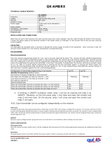
• TECHNICAL CHARACTERISTICS
System non compatible with RADIOBAND 1G.
RBAND/UMS RBAND/CSM
Frequency Multifrequency system (433 MHz, 868 MHz) Multifrequency system (433 MHz, 868 MHz)
Memory 6 transmitters (3 on relay 1, 3 on relay 2) 6 transmitters (3 on relay 1, 3 on relay 2)
Relay numbers 2 relays ---
Power supply 12/24V ac/dc pluggable
Power supply range
9-35V dc
8-28V ac
---
Relay contacts 1A 1A
Consumption
standby/operating
Max 255mA Max 20mA
Autotest signal input Two 0/12/24V ac/dc inputs with selectable polarity integrated
Radiated power < 25mW < 25mW
Operating temperature -40ºC a +85ºC -40ºC a +85ºC
Seal IP54 (with IP65 cable seals) IP20
Box size 82 x 190 x 40mm 50 x 47 x 14mm
Range 10 metres 10 metres

COD. 1248033-GB / 1.0
RBAND/UMS - RBAND/CSM
- 2 -
CHECK
BUTTON
PROGRAMMING
BUTTON
FREQUENCY
SELECTOR
SWITCH
CONTROL PANEL
CONNECTION
CHECK
BUTTON
SAFETY EDGE OR
VOLT FREE CONTACT
SELECTOR
PROGRAMMING
BUTTON
FREQUENCY
SELECTOR SWITCH
RESET JUMPER
POWER
SUPPL
Y
R1 / R2
OU
TP
U
T
S
AUTO TEST
CONNECTION
CURRENT DETECTO
R
CONNECTION

COD. 1248033-GB / 1.0
RBAND/UMS - RBAND/CSM
- 3 -
• INSTALLATION PROCEDURE AND BASIC WIRING
MECHANICAL INSTALLATION RBAND/UMS
Fix the back of the box to the wall, using the wall plugs and screws supplied. Install the receiver, close to the door and avoid
metal surfaces between the receiver and the transmitter. Pass the cables through the bottom of the receiver. Connect the
power cables to the terminals of the printed circuit, following the indications of the connections diagram. Store transmitters.
Fix the front of the receiver to the back with the screws supplied for the purpose.
INSTALLATION ADVISES
Use the cable entry at the bottom of the receiver for the power supply and control connections.
The transmitter and receiver antenna must be parallel to each other for optimum signal reception.
Fit the batteries ensuring the correct polarity.
After programming the transmitter re-fit the front cover of the transmitter and the receiver.
MECHANICAL INSTALLATION RBAND/CSM
Connect to a control panel using a connector for safety devices. The power supply must be disconnected.
OPTIONS SELECTOR
Option No ON OFF
1 – Channel selection See table Multifrequency system See table Multifrequency system
2 – Channel selection See table Multifrequency system See table Multifrequency system
3 – Autotest polarity Negative polarity Positive polarity
4 – Relay 2 function Low battery indicator Normal function
Nota: Options 3 and 4 non available in RBAND/CSM
• ELECTRICAL CONNECTIONS
>20cm

COD. 1248033-GB / 1.0
RBAND/UMS - RBAND/CSM
- 4 -
The outputs can be configured to act an 8k2 or as a N/C Contact.
- The relay jumper in position BS the output is 8K2.
- The relay jumper in position CS the output is N/C Contact.
AUTOTEST SIGNAL
Whilst the RadioBand receiver monitors the RadioBand transmitter every 20 seconds, the system must be tested at the exact
time when the door/gate receives a signal to move. This test is done with the auto test signal.
The auto test signal ensures that all of the parts of the safety edge system are ok before the door/gate can operate.
The auto test signal is sent from the door/gate control panel and activates the output from the RadioBand receiver. When the
door/gate control panel receives this output it allows the door/gate to start.
AUTO TEST
CONNECTION
POWER
SUPPLY
+
-
TO SAFETY EDGE / CONTACT
INPUT OF CONTROL PANEL
TO SAFETY EDGE / CONTACT
INPUT OF CONTROL PANEL
UVW
CURRENT DETECTOR
CONNECTION
CONTROL PANEL
MOTOR CONNECTION
CONNECTION NEEDED IF YOU OPERATE WITH OPTO SAFETY EDG
E
WITH
OU
T A
U
T
O
TE
ST

COD. 1248033-GB / 1.0
RBAND/UMS - RBAND/CSM
- 5 -
The RadioBand receiver will accept two types of auto test signal. The function selector switch must be put in the correct
position for the auto test signal.
1- Positive autotest: A 0V signal which switches to 12/24V ac/dc for the auto test.
2- Negative autotest: A 12/24V ac/dc signal which switches to 0V for the auto test.
Both autotest inputs must be connected althought one of them is not used.
The auto-test signal from the control panel must only remain activated for up to 3 seconds.
In order to comply with the EN ISO 13849-1 safety standard, it is necessary to connect the autotest signal.
• PROGRAMMATION
Each safety edge transmitter must be learnt into the appropriate channel of the safety edge receiver.
Mode Configuration of transmitter programming in the receiver. Led R1 Led R2
1 By pressing the transmitter, relay 1 on the receiver will be activated ON OFF
2 By pressing the transmitter, relay 2 on the receiver will be activated OFF ON
3 By pressing the transmitter, the two relays will be activated at the same time ON ON
4 The relays are activated 1st relay by channel 1 (operate as normal operation for connecting a
safety element) and 2nd relay by channel 2 (operates as a normally open contact for
connecting an auxiliary input) (connection of an auxiliary input, the sender transmits the
status of the auxiliary input to the second relay of the receiver)
Flashing
Flashing
Notes:
- Modes 1, 2 and 3: Up to 6 transmitters (3 on output R1 and 3 on output R2) can be connected to the receiver in modes
1, 2 and 3.
- Mode 4: In this mode only 3 transmitters can be connected to the receiver. The second relay cannot make the function
of indicating low battery.
- Each transmitter can be configured independently on the receiver.
- A Transmitter should only be connected to one receiver.

COD. 1248033-GB / 1.0
RBAND/UMS - RBAND/CSM
- 6 -
If 10 seconds pass without programming a transmitter, the receiver will exit the programming mode.
If when programming a transmitter the receiver’s memory is full then it will emit 7 beeps of 0.5 sec and exit the
programming mode.
MULTIFREQUENCY CHANNEL
For a better communication between the devices of the system and to avoid possible interferences, the system incorporates
4 communication channels selectable by the users.
Moreover, it incorporates a security channel that will be used for guarantee the functioning in front of possible
communications failures on the selected channel.
Channels Frequency bands (MHz) Switch 1 Switch 2
Channel 1 (*) 868,700 – 869,200 OFF OFF
Channel 2 868,000 – 868,600 ON OFF
Channel 3 869,400 – 890,650 OFF ON
Channel 4 869,700 – 870,000 ON ON
Security channel 433,050 – 434,790 --- ---
(*) Default recommended channel
In front of low levels of signal (see function CHECK) or interferences on the selected channel, it could be possible to select
another communication channel, being necessary to program again all the transmitters.
• MAINTENANCE
SYSTEM CHECK
This function has to be used to check the operation and range of all the devices once the installation has been carried out.
Press the receiver’s CHECK button for at least 1 second to enter check mode. The indicator light will come on and four
beeps will be heard.
Perform a complete door opening and closing manoeuvre. During the system check a beep will be heard every 1,5 seconds.
CORRECT OPERATION OF THE SYSTEM
If no other acoustic signal is heard on completing the manoeuvre, the system is operating correctly. Either press the
CHECK button again or wait 5 minutes and the receiver will exit checking automatically, indicating with two beeps
that the check has been correct. The check indicator light will go out.
DETECTION OF TRANSMISSION FAILURE
If the communication with a transmitter fails during checking, or the communication is deficient (for instance, too
many communication retries or poor coverage), the receiver emits three consecutive beeps, indicating that an error
has occurred. Halt the door manoeuvre and press the safety edges installed to detect what has failed.
- If a single beep is heard on pressing a safety edge, this means that the safety edge is correct.
- If three consecutive beeps are heard on pressing the safety edge, this means that the safety edge has failed.
In this event, it is recommended changing the orientation of the transmitting-receiving aerials or installing
an AED-868 or FLAT-868 outdoor aerial to ensure the desired range.
On exiting check mode, seven consecutive beeps will be heard and the indicator light will flash continuously.
Perform another system check until the result is correct.
Signal coverage
After pressing one of the installed safety edges, continuous flashes, ranging from 1 to 5, indicate the signal coverage
for this safety edge at the time it was pressed.

COD. 1248033-GB / 1.0
RBAND/UMS - RBAND/CSM
- 7 -
Number of check LED
flashes
Coverage Result of check
1 Very weak Safety edge failure
2 Weak OK
3 Normal OK
4 Good OK
5 Very good OK
TOTAL RESET
In programming mode, keep the programming PROG button pressed down and make a bridge with the “MR” reset jumper
for 3s. The receiver will emit 10 warning sound signals and then more at a faster frequency, indicating that the operation
has been carried out. The receiver will stay in programming mode.
Wait for the receiver to exit the programming mode.
The receiver will exit the programming mode emitting two 1 sec beeps. If 10 seconds pass without programming a
transmitter, the receiver will exit the programming mode.
TRANSMITTER BATTERY LOW INDICATOR
In normal conditions the battery should operate for two years.
If the battery of a transmitter programmed into the receiver becomes low, the receiver will beep 4 times every 20 seconds. If
there is more than one transmitter programmed, each safety edge should be activated to identify, hearing the 4 beeps, which
transmitter has a low battery. If the battery power is low, replace it immediately.
When the second relay of the receiver is not used for a safety edge, it can be used as a battery low indicator. It will activate
the output relay when a transmitter with low battery is detected, useful to trigger an alarm. In this case the receiver will not
indicate low battery with the beeps. Put dipswitch 4 on the function selector to ON.
Note: Only available in mode 1 and in RBAND/UMS model.
REPLACING THE TRANSMITTER BATTERY
Remove the box cover. Replace the two used batteries with new ones, taking into account the polarity indicated by the
connector. Check that the new batteries support the same temperature range as those they are replacing.
REPLACING A TRANSMITTER
If a transmitter becomes damaged the whole system must be re-set and replacement and non-damaged transmitters must
then be re-programmed into the receiver.
IMPORTANT ANNEX
Disconnect the power supply whenever you proceed to the installation or repair of the control panel.
In accordance with the European low voltage directive, you are informed of the following requirements:
· For permanently connected equipment, an easily accessible connection device must be incorporated into the cabling.
· This system must only be installed by a qualified person that has experience with automatic doors/gates and knowledge of
the relevant EU standards.
· The instructions for use of this equipment must always remain in the possession of the user.
· Terminals with a maximum section of 3.8mm2 must be used to connect the cables.
· The frequency of the RadioBand system does not interfere in any way with the 868 MHz remote control systems.
JCM TECHNOLOGIES, S.A. declares herewith that the product RBAND/UMS, RBAND/CSM complies with the requirements
of the 1999/5/ CEE R&TTE Directive, 2004/108/EC Directive on electromagnetic compatibility and 2006/95/EC on low
voltage, insofar as the product is used correctly.
CE CONFORMITY DECLARATION
See web www.motion-line.com
/