BBC Bircher XRF-RD User manual

Type
User manual

BBC Bircher XRF-RD is a dual channel receiver for XRF wireless transmission systems designed to monitor safety edges and switches on industrial doors and gates. It features two safety outputs (2 x 2 relays), an output for battery low indication, and an input for stationary sensors. With a maximum range of 60 meters and a reaction time of 15 milliseconds, the XRF-RD ensures reliable and quick communication between transmitters and receivers.

BBC Bircher XRF-RD is a dual channel receiver for XRF wireless transmission systems designed to monitor safety edges and switches on industrial doors and gates. It features two safety outputs (2 x 2 relays), an output for battery low indication, and an input for stationary sensors. With a maximum range of 60 meters and a reaction time of 15 milliseconds, the XRF-RD ensures reliable and quick communication between transmitters and receivers.

1
ON
1 2
ON
1 2
XRF-RD
ON
1 2
23
99
94
91 91
23
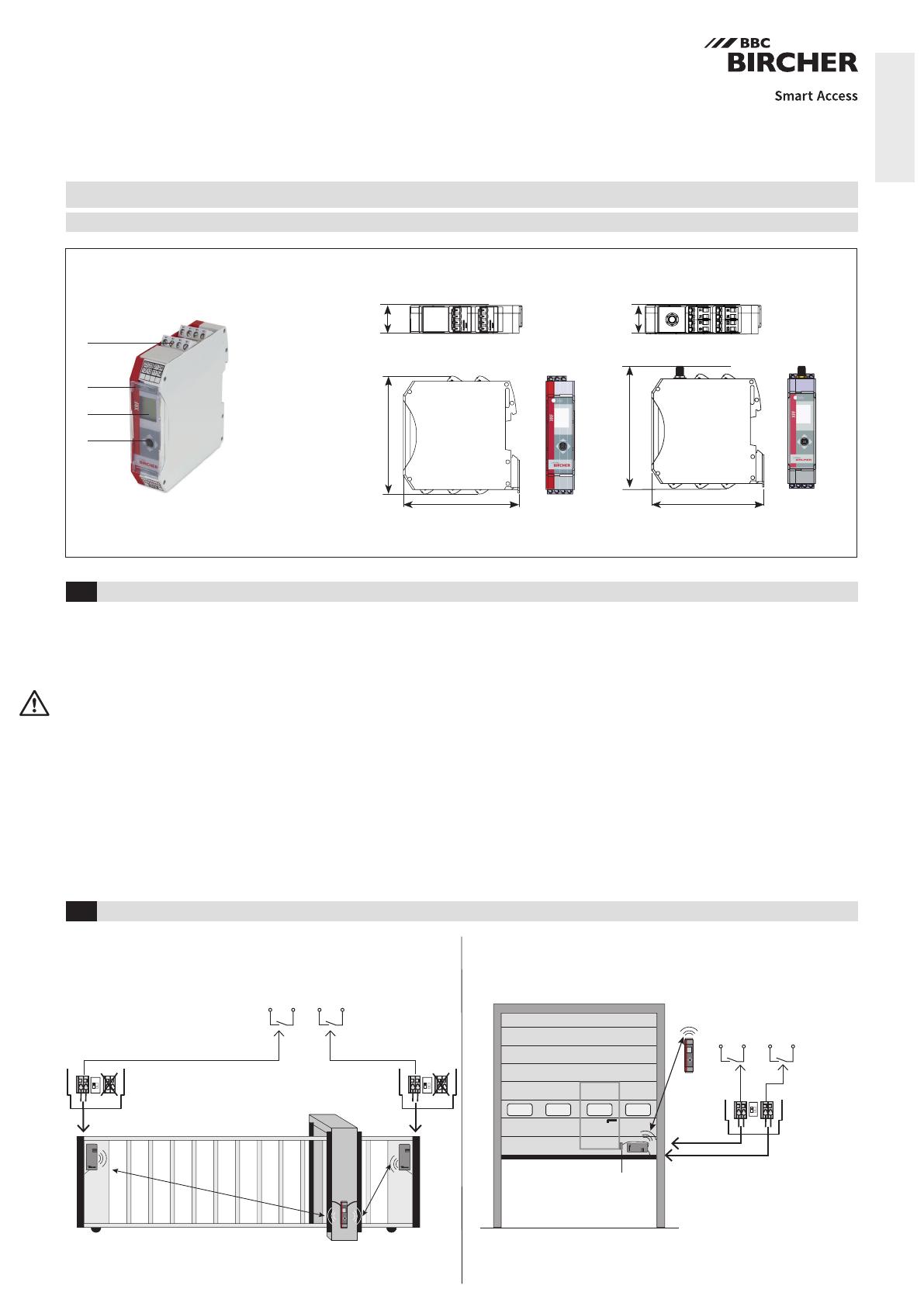
Dual channel receiver to XRF wireless transmission system
Original operating instructions
Intended use: Monitoring safety edges and switches on industrial doors and gates
Safety instructions
2 2Common applications
ENGLISH
404168D
10/22
XRF-RD XRF-RD.A (with antenna)
Receiver
Figure 1.a
Receiver
Transmitter
Door
switch
Figure 1.b
Tx1 Tx2
Receiver
Output
1
Output
1
Output
2
Output
2
Transmitter input 1 corresponds to receiver output 1
Transmitter input 2 corresponds to receiver output 2
Transmitter Tx1 (input 1) corresponds to receiver output 1
Transmitter Tx2 (input 1) corresponds to receiver output 2
Terminals
0.08 – 2.5 mm2
LED SYS
LCD display
Joystick
1
Read these operating instructions thoroughly before putting the device into
operation and keep them for future reference.
Do not use this product other than for its specied application.
Only trained and qualied personnel may install and initialize the device.
Only authorized factory personnel may perform hardware/software changes or
repairs to the product.
Failure to follow these safety precautions may cause damage to sensor or objects,
serious personal injury, or death.
It is the responsibility of the equipment manufacturer to carry out a risk assess-
ment and to install the system in compliance with applicable local, national and
international regulations, safety standards, codes and laws as well as the
Machinery Directive 2006/42/EC, should this apply.
Always consider the safety functions of your applications as a whole, never just in
relation to one individual section of the system.
The installer is responsible for testing the system to ensure it meets all applicable
safety standards.
Safety devices that are classied as Category 2 according to EN ISO 13849-1 must
be tested regularly – at least once per cycle.
If the safety device is not requested operationally at least once a year, it must be
checked manually by the operator at least once a year.
During the operation of electrical components
e. g. in the case of a short circuit, hot and ionised gases can be emitted;
protection covers must not be removed!
The sensor should only be operated from a safety extra low voltage (SELV) system
with safe electrical separation according to EN 61558. The wiring must be
protected against mechanical damage.
Check the voltage data on the label of the switching device.
Pay attention to all local relevant electrical safety regulations.
Ensure that the device/installations cannot be switched on.
• Ensure that the power supply is disconnected.
Protect the device with a housing against contamination or harsh environments.
Disconnect device from mains in the event of a fault.
After accessing the inside of the device, ensure the cover/protection seal is closed
tightly to achieve the designated protection rating.
Max.14 transmitters in this conguration Max.7 transmitters in this conguration
2
A1 A2 5 6
1 2 3 4 14 11 13 12
8k2 8k2
24 21 23 22
8k28k2
T2 T1
2
1
2
1
2
1
2
12
1
2
1
2
1
1 2 l
u
r
d
2
12
1
IN1 IN2
i
i
5.2 Bircher signal indicator (BSI) Details see supplementary sheet
5.3 Congure inputs for stationary sensors
Congure mode
5.1.a Pairing, using the rst inputs of dierent transmitters
5.1.b Pairing, using both inputs of transmitter
5 Conguration
3Installation
4Wiring
VIN Test Output 2
(Uth > 10 V AC/DC /
< 11 mA )
Only to be wired
in case of a
Cat. 2 application
Battery low
Output 3
Power supply
(12–36 V AC/DC)
(36 V AC/DC / 1 A)
Do not wire
12/13 and 14/11
simultaneously
(36 V AC/DC / 1 A)
Do not wire
23/22 and 24/21
simultaneously
(36 V AC/DC / 0.1 A)
Output 1
Press button
Press button
Press button
Transmitter Tx1
Transmitter Tx2
Transmitter(s)
Receiver
Receiver
Receiver
Receiver
Receiver
Receiver
Receiver
Receiver
Receiver
Transmitter Tx1
Transmitter Tx2
Transmitter(s)
Release button
Release button
Release button
Pair
to output 1
Pair
to output 2
Pair
to both outputs
Long press
joystick
Move joystick
left
Move joystick
right
Move joystick
upwards
Move joystick
acc. to requested
conguration (see 7.2)
LED
LED
LED
LED
LED
LED
LED
LED
Flashes
orange
Orange
Orange
Orange
Flashes
orange
Flashes
orange
Flashes
orange
Green Release
joystick
Press joystick
again
Press joystick
again
Beep
Beep
Beep
Beep
Beep
Beep
Beep
Beep
Beep
According to the application, e.g. gure 1.a or 1.b
See gure 1.aSee gure 1.b
Note: When using the NC outputs (13/12, 23/22), in Cat. 3 set-up, the wiring with the control must be permanently installed and protected against
external damage according to EN ISO 13849-2 Tab.D.4 or else Cat. 2 applies and a test signal is needed
(see also manual of transmitter)
Inputs for stationary sensing edges
Buzzer + LED ashing green level of Bircher signal indicator
3
OK?
2x
1
1 2 u
d
2
1
5.4 Congure test input
Leave conguration mode (always possible)
Clear pairings
7.1 Status LED, LCD, outputs
6System test, mandatory after each set-up!
7Receiver
Press each
safety edge
Receiver
Receiver
1 min.
Green
Green Orange Example shows
channel 1
Long press
joystick ...
... or wait
Move joystick
acc. to requested
conguration (see 7.2)
LED
LED LED
Press joystick
Beep
Beep
LED Display Output 1 Output 1 Output 2 Output 2 Output 3 Buzzer
SYS 14–11 13–12 24–21 23–22 5–6
No power supply CLOSED open CLOSED open open
Power-up red 1 2 CLOSED open CLOSED open open ends with
4x beep
System ready, no sensor pressed
*) both dots ashing
green
8k2 closed 8k2 CLOSED open
Sensor 1 pressed (main closing edge) orange 1CLOSED open 8k2 CLOSED open
Sensor 2 pressed (secondary closing
edge)
orange 28k2 CLOSED CLOSED open open
Stationary sensor 1 pressed (output 1) orange 1CLOSED open 8k2 CLOSED open
Stationary sensor 2 pressed (output 2) orange 28k2 CLOSED CLOSED open open
Wicket door open
(XRF-TW on channel 2)
orange 28k2 CLOSED CLOSED open open
Conguration:
a) Pairing, b) BSI, c ) Stationary edges,
d) Test Input
orange
ashing
2
1
a
2
1
b
2
1
c
1 2
d
CLOSED open CLOSED open open upon action
Conguration mode, memory full orange
ashing
1 2 CLOSED open CLOSED open open 10x
Low battery green
ashing
8k2 CLOSED 8k2 CLOSED CLOSED 3x
every min.
Test input active
*) 1st dot stable, 2nd dot ashing
green
*)
CLOSED open CLOSED open open
Error a) Tx lost 1x
red
ashing
2
1
a/c
2
1
b
2
1
d
2
1
d
CLOSED open CLOSED open open (see
8.2)
b) Broken cable between edge and
input, resistor out of range
2x
c) Empty battery 3x
d) System error 30 s
LED
Receiver
Press joystick,
and hold ( > 5 s)
Release
joystick
Flashes
orange
Beep 5x All pairings
deleted
Does the door/gate stop when the sensing
element is activated?
*)
4
3x
OK?
OK?
Designed in Switzerland / Made in China
BBC Bircher Smart Access, BBC Bircher AG, Wiesengasse 20, CH-8222 Beringen, www.bircher.com
11
2
12
1
2
1
2
12
1
2
1
2
1
2
1
2
1
1 2
2
1
2
1
1 2
2
11 2
*
* *
LED LED LED
8Trouble shooting
9Technical data
10 EU Declaration of Conformity
12 Contact
8.1 Warning indicator for low battery voltage
8.2 Errors (see 7.1)
To nd out which transmitter
has low battery voltage:
Press each edge.
To nd out which
transmitter causes
error indication:
Every minute Battery good Battery bad
Receiver
Supply voltage 12–36 V DC
12–36 V AC, 48–62 Hz
Power consumption max. 1.0 W
Safety outputs (2 x 2 relays) max. 36 V AC/DC; 1 A (NC with 1A fuse)
Output battery low (SSR) max. 36 V AC/DC; 0.1 A
Input stat. sensors Sensors with 8.2 kOhm resistor
Test input max. 36 V DC; 36 V AC, 48–62 Hz
max.11 mA
Uth > 10 V AC/DC
Antenna connection
(optional)
SMA (f)
Number of supported
sensors
max. 14
(stationary sensors included)
Mounting DIN-rail
Protection class IEC 60529 IP20
System
Operating frequency 868.3 MHz
Reaction time Typ. 15 ms
Range 60 m (at optimal condition)
According to EN ISO 13849-1 PLd
for Cat. 3 applications
+ test input for Cat. 2 applications
Operating temperature –20 °C to +60 °C
Beep Beep
Beep
See attachment
11 WEEE
Devices with this symbol must be treated separately during disposal. This must be done in accordance with the laws of
the respective countries for environmentally sound disposal, processing and recycling of electrical and electronic equipment.
7.2 Menu structure
Level 3:
Stationary edges
Level 2:
Bircher signal
indicator (BSI)
Level 1:
Pairing
Level 4:
Test input
Entry
Exit
Long press
joystick
Press
joystick
Press
joystick
Press
joystick
Press
joystick
IN1 to output 1
IN2 to output 2
to output 1 + 2 High active
IN2 to
output 2
to
output 2
IN1 to
output 1
to
output 1
none Low active
* default setting
Red Stays red
Flashes orange
or or
Transmitter good Transmitter with error
Details see
supplemen-
tary sheet
  • Page 1 1
  • Page 2 2
  • Page 3 3
  • Page 4 4

BBC Bircher XRF-RD User manual

Type
User manual

BBC Bircher XRF-RD is a dual channel receiver for XRF wireless transmission systems designed to monitor safety edges and switches on industrial doors and gates. It features two safety outputs (2 x 2 relays), an output for battery low indication, and an input for stationary sensors. With a maximum range of 60 meters and a reaction time of 15 milliseconds, the XRF-RD ensures reliable and quick communication between transmitters and receivers.

Ask a question and I''ll find the answer in the document

Finding information in a document is now easier with AI