
Form CP-RP/SC-V (7-16), P/N 132380 R3, Page 1
Instructions for Assembling Replacement Venter Motor & Motor
Mounting Plate
Applies: Replacement Kits, P/N’s 132377, 132378 & 132379 for (C)(H)(HC)RP/
RPV Series 3, 5 & 6 and (H)(S)SC; SC(A)(B)(E) Series 3 & 5 Heaters
Form CP-RP/SC-V (7-16)
Description/
Application
Obsoletes RZ/NA CP-RP/SC-V (Ver A.1)
These instructions apply to the replacement kits listed above. Each kit includes a venter motor
with a capacitor and a hardware bag; including a selection of mounting plates.
Prior to installation on the heater, the replacement venter motor must be attached to a new
mounting plate. To be multifunctional, the hardware package in each kit includes four motor
mounting plates that are used with all voltages of motors. Selection of the appropriate
mounting plate depends on the model and size of furnace being serviced.
Qty Description
1 Venter Motor and Capacitor Assembly
4 Motor Mounting Plates, one each of P/N; 131445, 131446, 131447 & 131448
2 Locking Nuts #8-32, P/N 31522
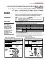
1. Verify Voltage Agreement:
Check the replacement motor label and the heater rating plate to verify the agreement of
the motor voltage and the supply voltage of the furnace being serviced.
Kit P/N’s 132377 132378 132379 132377
Supply Voltage 115V 208V & 230V 460V 575V
Venter Motor Assembly in the Kit 131410 131415 165986 131410
Venter Motor Assembly Includes:
Venter Motor
P/N 163891 163892 163893 163891
Magnetek # JE1F026 JE1F027 JE1F026 JE1F026
Capacitor
P/N 163894
Magnetek # 60P52-561-8
2. Select the Motor Mounting Plate:
Refer to the APPLICATIONS TABLES 1, 2, 3 & 4 and locate the Model/Size of furnace
being serviced. (NOTE: These instructions do not apply to RPV or SC Models prior to
Series 3). Measure each plate in the kit, comparing its size and hole size to the dimensions
on the drawing. Select the mounting plate that applies to the furnace being serviced. The
remaining other three mounting plates will not be used.
Components
Instructions
APPLICATION TABLE 1
Applies to:
Model Sizes Application Details
RP 125 - 350
460V furnaces manufactured prior
to 3/94 (Serial No Code ATC);
115/208/230/575 V furnaces
manufactured prior to 7/94
(Serial No Code ATG)
CRP 125 - 300
HRP 125 - 350
HCRP 125 - 300
RPV 125 - 350
Series 3, 5 & 6
ONLY
CRPV 125 - 300
HRPV 125 - 350
HCRPV 125 - 300
Select
Mounting
Plate P/N
131445
4-9/16”
(116mm)
3-1/4”Dia
(83mm)
APPLICATION TABLE 2
Applies to:
Model Size Application Details
CRP 400
460V furnaces manufactured prior
to 3/94 (Serial No Code ATC);
115/208/230/575 V furnaces
manufactured prior to 7/94
(Serial No Code ATG)
HCRP 400
CRPV 400
Series 3, 5 & 6
ONLY
HCRPV 400
Select
Mounting
Plate P/N
131446
5-3/4” (146mm)
5-3/4”
(146mm)
1-3/4”Dia
(44mm)
WARNING:
Turn off the gas
and the electric
before servicing
any heater. All
service should be
performed by a
qualied service
technician.

Form CP-RP/SC-V (7-16), P/N 132380 R3, Page 2
Specications & illustrations subject to change without notice and without incurring obligations.
©Nortek Global HVAC, LLC 2016. All rights reserved.
All marks are the property of their respective organizations.
O’Fallon, MO I Printed in U.S.A. (7/16)
FORM CP-RP/SC-V (7-16), PN132380 R3
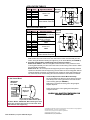
3. Remove the Venter Motor Assembly:
Mark and disconnect the venter motor wires. Remove the venter motor assembly from the
heater, saving all hardware including the support ring on SC Series Models (See FIGURE 1)
4. Assemble the New Motor and Mounting Plate as Selected in Step 2:
Model Series RP/RPV - With the rectangular bracket toward the motor, position the motor
mounting plate assembly over two of the motor studs. Use the locking nuts in the kit to attach
the motor studs to the bracket.
Model Series SC - Re-use the spacers and support ring from the original assembly. Place the
spacers over the motor studs and support ring over the bracket on the mounting plate. With the
rectangular bracket and support ring toward the motor, position the motor plate assembly over
two of the motor studs. Use the locking nuts in the kit to attach the motor studs to the bracket.
APPLICATION TABLE 3
Applies to:
Select
Mounting
Plate P/N
131447
Model Sizes Application Details
SC 125 - 300
Series 3 & 5
ONLY
HSC 125 - 300
SCA 125 - 300
SCB 125 - 300
SCE 125 - 300
SSC 250 - 300 Duct furnaces in packaged
Models SSCBL 500 & 600
4-7/8” (124mm)
4-7/8”
(124 mm)
1-3/4”Dia
(44mm)
APPLICATION TABLE 4
Applies to:
Select
Mounting
Plate P/N
131448
Model Sizes Application Details
RP 400
460V furnaces manufactured
prior to 3/94 (Serial No Code ATC);
115/208/230/575 V furnaces
manufactured prior to 7/94
(Serial No Code ATG)
HRP 400
RPV 400
Series 3, 5 & 6
ONLY
HRPV 400
SC 350 - 400
Series 3 & 5
ONLY
HSC 350 - 400
SCA 350 - 400
SCB 350 - 400
SCE 350 - 400
SSC 350 - 400 Duct furnaces in packaged
Models SSCBL 500 & 600
5-3/4” (146mm)
5-3/4”
(146mm)
1-3/4”Dia
(44mm)
Motor and
Capacitor
IMPORTANT:
All Models
5/16” (8mm)
Motor Support Ring, P/N 125346
required on SC Series Models ONLY
SC Series Models - IMPORTANT: When attaching the motor
to the plate, slide the spiral spacers over the motor studs
and install the motor support ring
FIGURE 1
- Assemble Motor & Plate and Attach
to the Venter Wheel
5. Install the Replacement Venter Motor Assembly:
Re-use the hardware to attach the venter wheel to the motor
shaft. Always leave a 5/16” gap between the wheel and the
motor mounting plate (see FIGURE 1).
Make wiring connections according to the wiring diagram.
Replace all panels.
Follow the instructions on the lighting instruction plate to
re-light the furnace.
CHECK ALL SAFETY FEATURES FOR
PROPER OPERATION
-
 1
1
-
 2
2


Ask a question and I''ll find the answer in the document
Finding information in a document is now easier with AI
Related papers
Other documents
-
Sterling 882.00268.00 User manual
-
Trane GHND-SVX01A-EN User manual
-
-
FIELD CONTROLS CV-4VR & CV-5VR Sidewall Power Venter Kit Installation guide
-
Thomas & Betts HEEDU User manual
-
-
-
-
Unbranded APD User manual
-