Reznor SC Operating instructions

Type
Operating instructions

This manual is also suitable for

Revision: CP-GC Parts (10-18) PN143147R9
FOR MODELS WITHOUT GAS CONVERSION KITS:
INDIRECT-FIRED MODEL RPV SERIES 6, 7, AND 8;
MODELS SC, SCA, SCB, AND SCE, SERIES 5 AND 6;
MODEL EEDU SERIES 3, 5, AND 6;
MODELS X, XE, PAK, AND RX SERIES 7 AND 8;
MODELS RG, RGB, RGBL, RP, RPB, RPBL, SSCBL, AND PGBL*;
DIRECT-FIRED MODEL ADF/ADFH WITHOUT ELECTRONIC MODULATION;
MODELS ADF/ADFH, RDF, AND DV**
*INCLUDES MODELS WITH PREFIX C, H, OR HC
**WITH CAPACITIES 750 MBH WITH ELECTRONIC MODULATION
GAS CONVERSION PARTS AND INSTRUCTIONS
Supersedes: CP-GC Parts (03-18) PN143147R8
TABLE OF CONTENTS
IMPORTANT SAFETY INFORMATION ...................................................................2
GENERAL INFORMATION ............................................................................. 2
DECODING HEATER MODEL NUMBERS. . . . . . . . . . . . . . . . . . . . . . . . . . . . . . . . . . . . . . . . . . . . . . . . . . . . . . . . . . . . . . . . . 2
SELECTING PARTS FOR GAS CONVERSION .............................................................3
Step 1: Select Spring Regulator Kit or Replacement Valve ...................................................3
Step 2: Select Natural Gas or Propane Gas Pilot Orifice .....................................................5
Step 3: Select Main Burner Orifices ..................................................................... 5
Step 4: Select Burner Air Shutter Assembly (for Natural Gas to Propane Conversion) ..............................7
Step 5: Conversion Disk or Conversion Label Selection .....................................................7
Step 6: Select Ignition Controller (for Natural Gas to Propane Conversion with Spark Pilot) .........................7
Step 7: Select Carryover Parts ........................................................................8
INSTALLATION OF GAS CONVERSION PARTS ...........................................................10
FLAME AND PRESSURE ADJUSTMENTS ................................................................15
Adjust Pilot Flame ..................................................................................15
Adjust Manifold Gas Pressure .........................................................................16
GAS CONVERSION OF DIRECT-FIRED FURNACES ........................................................ 17
STARTUP CHECKLIST ...............................................................................18
APPENDIX: GAS CONVERSION AND IGNITION CONVERSION KITS ..........................................19
2
CP-GC Parts (10-18) PN143147R9
IMPORTANT SAFETY INFORMATION
Please read all instructions before servicing this equipment. Pay attention to all dangers, warnings, cautions, and
notes highlighted in this manual. Safety markings should not be ignored and are used frequently throughout to
designate a degree or level of seriousness.
DANGER: A danger statement describes a potentially hazardous situation that if not avoided, will result in severe
personal injury or death and/or property damage.
WARNING: A warning statement describes a potentially hazardous situation that if not avoided, can result in severe
personal injury and/or property damage.
CAUTION: A caution statement describes a potentially hazardous situation that if not avoided, can result in minor
or moderate personal injury and/or property damage.
NOTE: A note provides important information that should not be ignored.
⚠ DANGER ⚠
Gas conversion should be made only by a qualified service technician. Improper conversion will
result in severe personal injury or death. The Manufacturer will not accept responsibility or liability
as a result of improper gas conversion. Due to increased cost of material and labor, gas conversion
should be discouraged as much as possible.
⚠ WARNING ⚠
Selection of replacement control parts from this manual and all servicing of products must be
done by a qualified service technician. Improper selection or servicing could result in death, severe
personal injury, and/or property damage.
GENERAL INFORMATION
NOTE: This instruction sheet includes parts and instructions for several models. It applies only
to the models listed on the front page and requires selection of individual parts. If the heater
being serviced is not listed on the front page, check the APPENDIX for a list of models that have
gas conversion kits. If your model is listed, contact your distributor to obtain a kit designed spe-
cifically for your application. If your heater model is not listed in either place, conversion parts
are not available.
All gas conversion must be done by a Distributor or other qualified service technician in accordance with these
instructions and in compliance with all codes and requirements.
In Canada, the conversion shall be carried out in accordance with the requirements of the Provincial Authorities
having jurisdiction and in accordance with the requirements of the CAN/CGA-B149 (.1 and .2) Installation Code.
This form supersedes and obsoletes all prior information regarding this subject.
DECODING HEATER MODEL NUMBERS
The identifying model number can be found on the heater rating plate. The rating plate identifies only original equipment,
so also check the actual gas valve label and look for any gas or ignition conversion labels. When converting fuels, it
is necessary that you have the complete heater model number. Refer to Table 1 to decode a heater model number.
NOTE: The complete model number, including all model suffixes, is required. Components
needed for gas conversion cannot be selected without this information and, depending on the
series, may not be available.
Table 1. Decoding Heater Model Numbers
Model No. Model Size Series No.
Suffix
RG 200-8-MB RG 200 8 MB (mechanical modulation)
3
CP-GC Parts (10-18) PN143147R9
SELECTING PARTS FOR GAS CONVERSION
Required conversion parts for models with conversion kits are all contained in the kit. Refer to the APPENDIX for a
list of models that have gas conversion kits.
NOTE: If the unit being converted has multiple furnace sections, order all parts for each furnace.
Required conversion parts for models without conversion kits must be selected individually. The following parts are
required for gas conversion:
Spring regulator or gas valve (refer to Step 1: Select Spring Regulator Kit or Replacement Valve)
Pilot orifice (refer to Step 2: Select Natural Gas or Propane Gas Pilot Orifice)
Burner orifices (refer to Step 3: Select Main Burner Orifices)
Burner air shutters (required only for conversion from natural gas to propane) (refer to Step 4: Select Burner Air
Shutter Assembly (for Natural Gas to Propane Conversion))
Conversion disk or conversion label (refer to Step 5: Conversion Disk or Conversion Label Selection)
Ignition controller (required only for conversion from natural gas to propane with spark pilot) (refer to Step 6: Select
Ignition Controller (for Natural Gas to Propane Conversion with Spark Pilot))
Carryover parts as required (refer to Step 7: Select Carryover Parts)
Select conversion parts in accordance with the following steps.
STEP 1: SELECT SPRING REGULATOR KIT OR REPLACEMENT VALVE
Refer to Table 2 for units with single-stage gas valves that require the installation of a spring regulator kit for gas
conversion. Refer to Table 3 for units with single-stage gas valves that require replacement gas valves for gas
conversion. Refer to Table 4 for units with two-stage gas valves that require replacement gas valves for gas conversion.
Refer to Table 5 for units with electronic modulation and spark pilot that require a replacement Maxitrol regulator
and solenoid valve replacement kit.
Table 2. Single-Stage Gas Valves that Require Installation of Spring Regulator Kit
Original Gas Valve Spring Regulator Kit
Propane to Natural Gas Conversion
Natural Gas to Propane Conversion
1
PN Manufacturer’s PN PN Manufacturer’s PN PN Manufacturer’s PN
82196, 82197,
82198, 82199,
82624, 82669
2
Robertshaw
700 & 7000
models
51572 Robertshaw #82445 65291 Robertshaw #82431
82398, 89370,
89371, 96301,
96303, 96308
Honeywell
V800 & VR8440
models
90204 Honeywell #391936 51749 Honeywell #391937
82395, 82396,
82397, 89397,
89398
3
, 96300,
96309, 96311
3
,
221525, 221526
White-Rodgers
36C & 36H
models
82525 White-Rodgers #F92-0656 82524 White-Rodgers #F92-0659
96299, 96302,
96307, 96310
4
,
121598, 121599,
121600, 147830,
147560, 150839,
150840, 176680,
176681, 208920,
209412
Honeywell
VR82 & VR83
models
98721 Honeywell #394588 98720 Honeywell #393691
1
If gas conversion requires lockout (required on indoor propane units in US and all propane units in Canada), select parts in Step 6: Select
Ignition Controller (for Natural Gas to Propane Conversion with Spark Pilot).
2
Use spring regulator kit to convert to natural gas on sizes up to 175 only. For sizes 200 through 400, change valve to PN 96301.
3
If used on natural gas units equipped with Maxitrol control systems, see Table 5.
4
Use spring regulator kit to convert to natural gas on sizes up to 165 only. For sizes 200 and 250, change valve to PN 121599. For sizes 300,
350, and 400, change valve using kit PN 222037.
4
CP-GC Parts (10-18) PN143147R9
SELECTING PARTS FOR GAS CONVERSION—CONTINUED
STEP 1: SELECT SPRING REGULATOR KIT OR REPLACEMENT VALVE—CONTINUED
Table 3. Single-Stage Gas Valves that Require Replacement Gas Valves
Propane to Natural Gas Conversion Natural Gas to Propane Conversion*
Original Gas Valve PN
(Manufacturer’s PN)
Replacement Gas Valve PN
(Manufacturer’s PN)
Original Gas Valve PN
(Manufacturer’s PN)
Replacement Gas Valve PN
(Manufacturer’s PN)
Units with Spark Pilot
89462
(Robertshaw #DER7100)
96307
(Honeywell #VR8204M1000)
89461
(Robertshaw #DER7100)
96310
(Honeywell #VR8204M1018)
Units with Direct Ignition
147134
(Robertshaw #7222DERLP)
260604
(Honeywell #VR8215S1263)
147133
(Robertshaw #7222DER)
260606
(Honeywell #VR8215S5215)
*If gas conversion of unit with spark pilot requires lockout (required on indoor propane units in US and all propane units in Canada), select
parts in Step 6: Select Ignition Controller (for Natural Gas to Propane Conversion with Spark Pilot).
Table 4. Two-Stage Gas Valves that Require Replacement Gas Valves
Propane to Natural Gas Conversion
Natural Gas to Propane Conversion
1
Original Gas Valve PN
(Manufacturer’s PN)
Replacement Gas Valve PN
(Manufacturer’s PN)
Original Gas Valve PN
(Manufacturer’s PN)
Replacement Gas Valve PN
(Manufacturer’s PN)
Size 75–250 Size 300–400 Size 75–400
Units with Match-Lit Pilot
62967
(Honeywell #V850A)
96306
(Honeywell #V850E)
115352
(White-Rodgers #36C41)
115351
(White-Rodgers #36C40,
3/4-inch)
2
62966
(Honeywell #V850A)
96304
(Honeywell #V850E)
3
96305
(Honeywell #V850E)
3
115351
(White-Rodgers #36C40)
115352
(White-Rodgers #36C41,
3/4-inch)
2
Units with Spark Pilot
87431
(White-Rodgers #36D13)
96312
(White-Rodgers #36D13)
177395
(Honeywell #VR8204)
177398
(Honeywell #VR8304)
177396
(Honeywell
#VR8204Q,
1/2-inch)
4
177397
(Honeywell
#VR8304Q,
3/4-inch)
2,4
87430
(White-Rodgers #36D13)
87432
(White-Rodgers #36D13)
177396
(Honeywell #VR8204)
177397
(Honeywell #VR8304)
177398
(Honeywell #VR8304Q,
1/2 × 3/4-inch)
4,5,6
1
Lockout is required for indoor propane models in US and for all propane models in Canada on units with spark pilot. If equipped with
Johnson Controls model G67BG-2 or G67BG-5, change ignition controller using kit PN 257473. If lockout is required for any other model,
change ignition controller to PN 257010 (refer to Step 6: Select Ignition Controller (for Natural Gas to Propane Conversion with Spark
Pilot)).
2
Field-provided reducer is required for 1/2-inch manifold.
3
Honeywell model V85OE valve change requires male compression nut PN 9664 (Baso #43283-2) for 1/4ʺ pilot tubing connection. Remove
pilot tubing fitting supplied with new valve.
4
New valve bracket (PN 194152) is required for EEDU 300, 350, and 400 when replacing valve 177395, 177396, 177397, or 177398.
5
Requires field compression fitting PN 9664 (Baso #43283-2) for 1/4-inch pilot tubing connection. Remove pilot tubing fitting supplied with
valve.
6
Field-provided reducer is required for 3/4-inch manifold on sizes 300–400.
NOTE: Two-stage is identified with suffix “2” in model number (e.g., XE300-2).
5
CP-GC Parts (10-18) PN143147R9
Table 5. Units with Electronic Modulation
1
and Spark Pilot that Require Replacement Maxitrol Regulator
and Solenoid Valve Replacement Kit
Original Gas Valve PN
(Manufacturer’s PN)
Size 75–125 Size 150–200 Size 225–400
Replacement
Regulator PN
(Maxitrol Model)
Solenoid
Valve
Replacement
Kit PN
Replacement
Regulator PN
(Maxitrol Model)
Solenoid
Valve
Replacement
Kit PN
Replacement
Regulator PN
(Maxitrol Model)
Solenoid
Valve
Replacement
Kit PN
Propane to Natural Gas Conversion
157167
(White-Rodgers #36C68)
157168
(White-Rodgers #36C68)
42278
(Maxitrol #MR410,
1/2-inch)
221634
42279
(Maxitrol #MR510,
1/2-inch)
221634
42280
(Maxitrol #MR510,
3/4-inch)
2
221634
Natural Gas to Propane Conversion
3
89398
(White-Rodgers #36C68)
96311
(White-Rodgers #36C68)
156462
(Maxitrol #MR410H-1,
1/2-inch)
4
221634
156463
(Maxitrol #MR510H-1,
1/2-inch)
4
221634
156464
(Maxitrol #MR510H-1,
3/4-inch)
2,4
221634
1
Electronic modulation control is identified with suffix MV in model number (e.g., RP400-MV). It does not apply to modulation options AG 39,
40, 41, and 42.
2
Field-provided reducer is required for 1/2ʺ manifold.
3
Lockout is required for indoor propane models in U.S. and for all propane models in Canada. If equipped with Johnson Controls model
G67BG-2 or G67BG-5, change ignition controller using kit PN 257473. If equipped with UTC model 1003-638-A, change ignition controller to
PN 257010 (refer to Step 6: Select Ignition Controller (for Natural Gas to Propane Conversion with Spark Pilot)).
4
Add time delay relay PN 89661 to prevent delayed ignition. Consult factory for wiring diagram.
NOTE: Electronic modulation control is identified with suffix “MV” in model number (e.g.,
RP400-MV). This does not apply to modulation options AG 39, 40, 41, and 42.
STEP 2: SELECT NATURAL GAS OR PROPANE GAS PILOT ORIFICE
Refer to Table 6 for pilot orifice selection.
NOTE: Required pilot orifice quantity is always one (1).
Table 6. Pilot Orifice Selection
Model*
Propane to Natural Gas Conversion Natural Gas to Propane Conversion
Type PN Type PN
Standing Pilot
X, XE, CX, CXE, PAK, CPAK series 7 or 8 6218 46392 4211 42089
Spark Pilot
EEDU 75-400 prior to series 6 7221 63088 4209 37801
EEDU 75-400 series 6 9731 103034 9733 98695
X, XE, CX, CXE, PAK, CPAK series 7 or 8 7221 63088 4209 37801
SC, SCA, SCB, SCE series 6 7715 93973 9715 126024
RX, CRX series 7 or 8
7223 63397 4209 37801
SC, SCA, SCB, SCE series 5
RPV, CRPV series 6, 7, and 8
All RG, CRG, RGB, CRGB, RP, CRP, RPB, CRPB,
RGBL, CRGBL, RPBL, CRPBL, SSCBL, PGBL
*Also applicable to these models with suffix letter “H”.
STEP 3: SELECT MAIN BURNER ORIFICES
Refer to Table 7 for main burner orifice selection.
NOTE: Table 7 is not applicable for high-altitude operation. When installation is above an eleva-
tion of 2000 feet, the unit must be de-rated. Consult your Distributor for proper orifice size.
6
CP-GC Parts (10-18) PN143147R9
Table 7. Main Burner Orifice Selection
Size
Orifice
Quantity
Propane to Natural Gas Conversion Natural Gas to Propane Conversion
Drill Size Burner Orifice PN Drill Size Burner Orifice PN
(H)EEDU Series 3, 5, and 6
75 4 45 38678 1.20 mm 63003
100 4 41 11792 1.45 mm 61652
125 5 41 11792 1.45 mm 61652
140 5 38 45870 1.55 mm 61653
170 6 38 45870 1.55 mm 61653
200 7 38 45870 1.55 mm 61653
225 8 38 45870 1.55 mm 61653
250 9 39 45871 1.55 mm 61653
300 11 39 45871 53 9789
350 13 39 45871 53 9789
400 15 39 45871 53 9789
Models X, PAK, RX Series 7 and 8; All Models RG, RGB, RGBL, PGBL
1
75 4 45 38678 1.20 mm 63003
100 4 41 11792 1.45 mm 61652
125 5 41 11792 1.45 mm 61652
150 7 43 11828 55 11830
175 7 41 11792 1.45 mm 61652
200 9 43 11828 55 11830
225 9 41 11792 1.45 mm 61652
250 12 44 11833 55 11830
300 12 41 11792 1.45 mm 61652
350 14 41 11792 1.45 mm 61652
400 16 41 11792 1.45 mm 61652
D300 16 45 38678 1.20 mm 63003
Models RPV Series 6, 7, and 8; Models SC, SCA, SCB, SCE Series 5 and 6; All Models RP, RPB, RPBL
1
100 4 41 11792 1.45 mm 61652
125 5 42 84437 1.45 mm 61652
150 7 44 11833 55 11830
175 7 42 84437 1.45 mm 61652
200 9 43 11828 55 11830
225 9 42 84437 1.45 mm 61652
250 12 44 11833 55 11830
300 12 42 84437 1.45 mm 61652
350 14 42 84437 1.50 mm 93410
400 16 42 84437 1.45 mm 61652
D300 16 45 38678 1.20 mm 63003
Models CX, CXE, CRX, CPAK Series 7 and 8; Models CRPV Series 6, 7, and 8; All Models CRG, CRGB, CRP, CRPB, CRGBL, CRPBL
2
75 4 45 38678 1.20 mm 63003
100 4 43 11828 55 11830
125 5 43 11828 55 11830
175 7 43 11828 55 11830
225 9 43 11828 55 11830
250 12 45 38678 1.20 mm 63003
300 12 43 11828 55 11830
350 14 43 11828 55 11830
400 16 43 11828 55 11830
1
Also applies to models listed with prefix H. Do not use on models with prefix C.
2
Also applies to these C models listed with prefix H.
SELECTING PARTS FOR GAS CONVERSION—CONTINUED
STEP 3: SELECT MAIN BURNER ORIFICES—CONTINUED
7
CP-GC Parts (10-18) PN143147R9
STEP 4: SELECT BURNER AIR SHUTTER ASSEMBLY (FOR NATURAL GAS TO PROPANE
CONVERSION)
NOTE: Do not order a burner air shutter assembly if the natural gas unit is already equipped
with optional factory-installed air shutters. Burner air shutters are required when converting to
propane.
Refer to Table 8 for burner air shutter assembly selection.
STEP 5: CONVERSION DISK OR CONVERSION LABEL SELECTION
Refer to Table 9 for conversion disk or conversion label selection.
Table 8. Burner Air Shutter Assembly Selection
Model
Size
75 & 100 125 140 150 170 175 200 225 250 300 350 400
Burner Air Shutter Assembly PN
EEDU, HEEDU
1
165684 165685
165686
165687 165688 165689 165690 165691 165692
55552 46109 46113 46115 46117 46119 46121 46123 46125
X, XE, PAK, RX, , RPV, SC,
SCA, SCB, SCE, SSCBL, CX,
CXE, CRX, CRPV, RG, CRG,
RGB, CRGB, RGBL, CRGBL,
RP CRP, RPB, CRPB, RPBL,
CRPBL, PGBL
2
15681 26562 26563 26563 15683 15683 15685 15685
3
26693 26885
3
1
No assembly PN—order both air shutter assembly and guide.
2
Also applies to these models with prefix H.
3
Assembly listed for size 400 also applies to size 300 with prefix D (DX, DRX, DRPV, HDX, HDRX, HDRPV).
Table 9. Conversion Disk or Conversion Label Selection
Heater with A.G.A. Rating Plate or CSA Rating Plate to ANSI Standards
Heater with C.G.A. Rating Plate
or CSA Rating Plate to ANSI Standards
Propane to Natural Gas Conversion Natural Gas to Propane Conversion
Conversion Label PN
Conversion Disk PN
1401 37752 64391
STEP 6: SELECT IGNITION CONTROLLER (FOR NATURAL GAS TO PROPANE CONVERSION
WITH SPARK PILOT)
NOTE: When converting indoor units with a spark pilot (indoor and outdoor in Canada) to pro-
pane, the ignition controller must have 100% lockout.
Refer to the flowchart shown in Figure 1 for ignition controller selection.
Figure 1. Ignition Controller Flowchart
HEATER EQUIPPED WITH:
PN 89314
(J/C #G67BG-2)
OR
PN 97782
(J/C #G67BG-5)
PN 257009
(UTC #1003-638-A)
PN 97547
(J/C G770NGC-4),
PN 234012
(J/C #G770NHC-1),
PN 257010
(UTC #1003-514)
IF IGNITION CONTROLLER
MUST BE CHANGED TO
LOCKOUT, ORDER KIT
PN 257473 AND
FOLLOW INSTRUCTIONS
IF IGNITION CONTROLLER
MUST BE CHANGED TO
LOCKOUT, ORDER
IGNITION CONTROLLER
PN 257010 WITH LOCKOUT
NATURAL GAS HEATER IS
ALREADY EQUIPPED WITH
IGNITION CONTROLLER WITH
LOCKOUT AND DOES NOT
NEED IGNITION CONTROLLER
CHANGE TO CONVERT
TO PROPANE GAS*
*IF UNIT IS GRAVITY VENTED AND AN AUTOMATIC VENT DAMPER IS ALSO BEING ADDED, IGNITION
CONTROLLER MAY NEED TO BE REPLACED. AVAILABILITY VARIES BY IGNITION CONTROLLER.
PN 97547 (JOHNSON CONTROLS #G770NGC-4) REQUIRES INSTALLATION OF KIT PN 257473. PN
234012 (JOHNSON CONTROLS #G770NHC-1) AND PN 257010 (UTC #1003-514) REQUIRE NO
CHANGE AS EACH OF THESE CONTROLLERS ACCOMMODATES AN AUTOMATIC VENT DAMPER.
8
CP-GC Parts (10-18) PN143147R9
SELECTING PARTS FOR GAS CONVERSION—CONTINUED
STEP 7: SELECT CARRYOVER PARTS
Step 7a: Carryover Lighter Tube System Determination
NOTE: Step 7a applies to models (H)SC, SCA, SCB, SCE series 5 and 6; models (H)X, (H)CX,
(H)XE, (H)CXE, (C)PAK; (H)RX, (H)CRX series 7 and 8; models (H)RPV, (H)CRPV series 6 and 8;
and all models (H)RG, (H)CRG, (H)RGB, (H)CRGB, (C)RGBL; (H)RP, (H)CRP, (H)RPB, (H)CRPB,
(C)RPBL as indicated.
Visually inspect the burner rack to determine whether or not it is factory-equipped with a carryover lighter tube system.
See Figure 2 for burner rack options, which include 1) a burner rack without a carryover lighter tube, 2) a burner
rack with a carryover lighter tube without a regulator (used with natural gas), and 3) a burner rack with a regulated
carryover lighter tube (used with propane).
Burner Rack Without
Carryover Lighter Tube
Burner Rack with Lighter
Tube Carryover System
Without Regulator
(Used with Natural Gas)
Burner Rack with Lighter Tube
Carryover System with Regulator
(Used with Propane Gas)
No Carryover
Carryover
is at the burner
end.
Carryover
Regulator
and Tubing
Applies only to natural gas
on (H)SC, SCA, SCB, SCE
Series 6; (H)X, (H)XE, PAK
Series 8; and PGBL
NOTE: Some older models did
not have a carryover tube; parts
are no longer available to convert
those units.
Figure 2. Burner Rack Options
Step 7b: Carryover Lighter Tube System for Propane to Natural Gas Conversion
NOTE: Step 7b applies to models (H)SC, SCA, SCB, SCE series 5 and 6; models (H)X, (H)CX,
(H)XE, (H)CXE, (C)PAK; (H)RX, (H)CRX series 7 and 8; models (H)RPV, (H)CRPV series 6 and 8;
and all models (H)RG, (H)CRG, (H)RGB, (H)CRGB, (C)RGBL; (H)RP, (H)CRP, (H)RPB, (H)CRPB,
(C)RPBL as indicated.
For propane to natural gas conversions, order the carryover lighter tube orifice listed in Table 10 (if required) plus
the following:
One (1) elbow, brass (PN 93388)
One (1) tube, carryover, 8-3/4 (PN 93389)
One (1) fitting, compression (PN 9664)
NOTE: For units with multiple furnaces, order parts for each furnace.
9
CP-GC Parts (10-18) PN143147R9
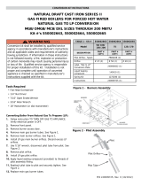
Table 10. Carryover Lighter Tube Orifice Selection (Propane to Natural Gas Conversions)
Model*
Part
Size
75 & 100 125 150 & 175 200 & 225 250 & 300 350 400
PN
Drill
Size
PN
Drill
Size
PN
Drill
Size
PN
Drill
Size
PN
Drill
Size
PN
Drill
Size
PN
Drill
Size
(H)X, (H)CX, (H)RX, (H)CRX,
(H)XE, (H)CXE series 7 and 8
All (H)RG, (H)CRG, (H)RGB,
(H)CRGB, RGBL, CRGBL, PGBL
Natural
gas
carryover
orifice
9870 70 9870 70 9680 65 10370 59 10370 59 9792 54 9792 54
(H)SC, SCA, SCB, SCE series 5
SSCBL
9680 65 9680 65 9680 65 10370 59 9792 54 11872 52
*Models (H)RP, (H)CRP, (H)RPB, (H)CRPB; Models (H)RPV, (H)CRPV Series 6, 7, and 8; Models SC, SCA, SCB, SCE Series 6; Models
(H)X, (H)XE, PAK Series 8; and Model PGBL do not require a carryover orifice change when converting from either propane to natural gas
or natural gas to propane. When converting to natural gas, remove the regulated carryover lighter tube (see Figure 2) and install the natural
gas carryover tube using the original (propane) carryover orifice.
Step 7c: Select Carryover Lighter Tube System for Natural Gas to Propane Conversion
NOTE: Step 7c applies to models (H)SC, SCA, SCB, SCE series 5 and 6; models (H)X, (H)CX,
(H)XE, (H)CXE, (C)PAK; (H)RX, (H)CRX series 7 and 8; models (H)RPV, (H)CRPV series 6 and 8;
and all models (H)RG, (H)CRG, (H)RGB, (H)CRGB, (C)RGBL; (H)RP, (H)CRP, (H)RPB, (H)CRPB,
(C)RPBL as indicated.
For natural gas to propane conversions, order the carryover lighter tube orifice system parts listed in Table 11 (if
required) plus one (1) regulated carryover assembly (PN 100712) as shown in Figure 3.
⚠ CAUTION ⚠
The regulator is factory-set at 1 inch of pressure at the outlet. DO NOT CHANGE PRESSURE SETTING.
NOTE: For units with multiple furnaces, order parts for each furnace.
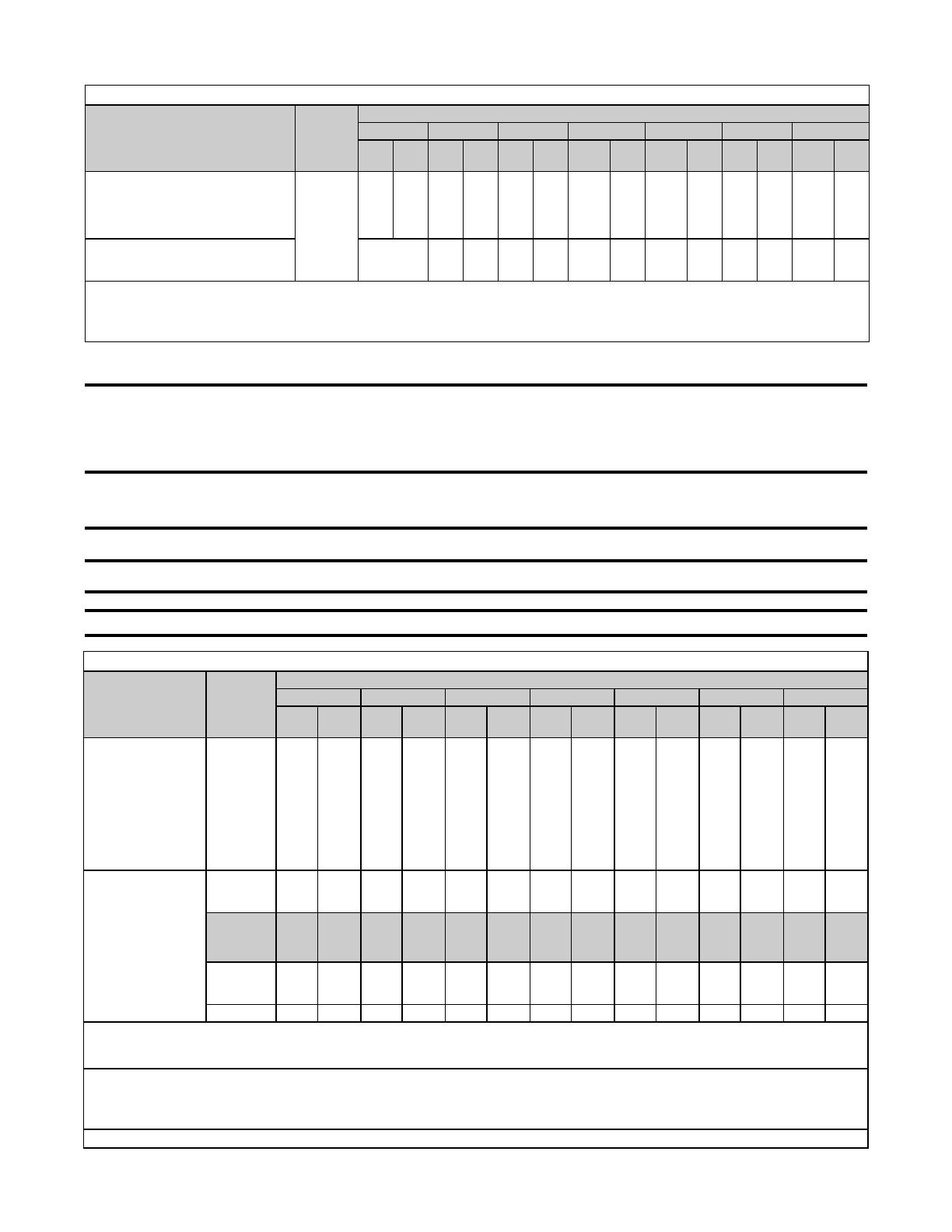
Table 11. Carryover Lighter Tube System Parts Selection (Natural Gas to Propane Conversions)
Model
1
Part
Size
75 & 100 125 150 & 175 200 & 225 250 & 300 350 400
PN
Drill
Size
PN
Drill
Size
PN
Drill
Size
PN
Drill
Size
PN
Drill
Size
PN
Drill
Size
PN
Drill
Size
(H)X, (H)CX,
(C)PAK, (H)RX,
(H)CRX, (H)XE,
(H)CXE series 7
(series 8 see
below)
2
All (H)RG, (H)CRG,
(H)RGB, (H)CRGB,
(C)RGBL
2
Propane
carryover
orifice
9870 70 9870 70 9680 65 9680 65 10370 59 9791 56 9791 56
(H)SC, SCA, SCB,
SCE series 5
SSCBL, (H)SC,
SCA, SCB, SCE
series 6
2
(H)X, (H)XE, PAK
series 8
2
PGBL
2
Propane
carryover
orifice
9870 70 9870 70 9870 70 9680 65 10370 59 38274 57 38274 57
Part PN
LG
3
PN
LG
3
PN
LG
3
PN
LG
3
PN
LG
3
PN
LG
3
PN
LG
3
Carryover
lighter tube
for burner
9899 12-3/8 9859 15-1/8 9821 20-5/8 9783 26-1/8 9747 34-7/8 9711 39-7/8 9520 45-3/8
Drip shield 15015 15014 15013 15012 15011 15010 14957
1
(H)RP, (H)CRP, (H)RPB, (H)CRPB, (H)RPV, (H)CRPV series 6, 7, and 8 do not require a carryover orifice change when converting from
either propane to natural gas or natural gas to propane. When converting to propane, they do require the addition of the regulated carryover
assembly (PN 100712) using the original (natural) carryover orifice.
2
(H)SC, SCA, SCB, SCE series 6; (H)X, (H)XE, PAK series 8; and PGBL do not have a lighter tube carryover system on a natural gas
burner. When converting to propane, remove the burner and remove the factory-installed flash carryover from the orifice end of the burner
rack—do not remove the flash carryover from the other end of the burner rack. Order the drip shield and carryover lighter tube listed by PN
and install as shown in Figure 4.
3
LG = length in inches.
10
CP-GC Parts (10-18) PN143147R9
Figure 3. Regulated Carryover Assembly for Propane Gas
SELECTING PARTS FOR GAS CONVERSION—CONTINUED
STEP 7: SELECT CARRYOVER PARTS—CONTINUED
Step 7c: Select Carryover Lighter Tube System for Natural Gas to Propane Conversion—Continued
Figure 4. Carryover Lighter Tube and Drip Shield
INSTALLATION OF GAS CONVERSION PARTS
⚠ WARNING ⚠
All gas conversions are to be done by a qualified service technician in accordance with these
instructions and in compliance with all codes and requirements of authorities having jurisdiction.
Failure to follow instructions could result in death, serious injury and/or property damage. The
qualified agency performing this work assumes responsibility for this conversion.
NOTE: Field-supplied hardware is required but differs by model and size. Read the instructions
before beginning to determine what hardware is required.
Install selected gas conversion parts as follows (these instructions apply to either all models or to specific models
and sizes, as noted).
1. Check to ensure that selected gas conversion parts are appropriate for furnace model and size being converted.
2. If heater is installed, shut OFF gas supply at shutoff valve upstream of combination valve.
3. Disconnect electrical supply.
4. Remove burner rack in accordance with instructions that apply to heater being converted. Figure 5 shows a
burner rack removed from a model SC unit.
NOTE: SC series burner racks include a burner rack skirt that is used only on separated-com-
bustion models.)
Carryover Lighter Tube
and Drip Shield for Burner
Remove Flash Carryover and Install
Carryover Lighter Tube and Drip Shield
Drip
Shield
Carryover
Lighter Tube
Carryover
Lighter Tube
Drip
Shield
11
CP-GC Parts (10-18) PN143147R9
Figure 5. SC Series Burner Rack with Burner Rack Skirt
a. Remove side panel from unit.
b. Disconnect pilot tubing and thermocouple or sensor lead from pilot.
c. Disconnect electric leads.
d. Uncouple union in gas supply to permit removal of burner rack.
5. Replace burner orifices.
a. Remove two screws that secure bottom of burner rack assembly.
b. Slide drawer-type burner rack out of heater.
c. If burner rack is equipped with carryover lighter tube, break connection at manifold fitting and remove manifold
bracket screws and manifold.
d. Install replacement burner orifices.
⚠ WARNING ⚠
Do not attempt to drill orifices. Use factory-supplied orifices only.
6. Replace pilot orifice.
a. Remove screws and lift out pilot burner.
b. Install replacement pilot orifice.
7. Install valve regulator spring kit.
⚠ WARNING ⚠
The manufacturer of the spring kit and the gas valve must be the same. Spring kits of different
manufacturers are not interchangeable. A spring kit must be used only in the valves for which the
kit is designated.
a. Follow valve manufacturer’s installation instructions that are included with spring kit.
b. Following spring kit installation, it is necessary to adjust spring for correct manifold pressure. This adjustment
can be made only after heater is in operation. Follow instructions in Adjust Manifold Gas Pressure.
8. Install burner air shutters (for natural gas to propane conversion).
⚠ WARNING ⚠
Failure to install and/or adjust air shutters according to directions could cause death,
personal injury, and/or property damage.
NOTE: All of these heaters require burner air shutters when operated on propane. If converting
to propane and the heater does not have air shutters, follow the installation instructions that
apply. If converting to natural gas, it is not necessary to remove the shutters, but the shutters
should be adjusted to full open position.
12
CP-GC Parts (10-18) PN143147R9
INSTALLATION OF GAS CONVERSION PARTS—CONTINUED
a. Install burner air shutters—on models EEDU and HEEDUin accordance with following steps (see Figure 6):
(1) Remove 1/4-inch sheet metal screws in manifold mounting angles and remove manifold assembly.
(2) Drill 7/32-inch holes in air shutter guide, 5/8 inch from top of guide and in 2-3/8 inch on both sides. Drill
additional 7/32-inch holes on 2-3/4-inch centers as required by heater size. Guide must fit flat against rear
support to prevent air leakage around air shutter.
(3) Position air shutter assembly on rear burner support so that clearance holes in lower edge of air
shutter guide fit over extruded holes located on rear burner support.
(4) Ensure that manifold orifices are centered in air shutter and re-attach manifold to rear burner support
using 1/4-inch sheet metal screws.
(5) Using 7/32-inch holes drilled in air shutter guide as guides, drill 1/8-inch holes through rear burner
support and fasten air shutter guide using #10 × 5/8-inch sheet metal screws.
(6) Adjust air shutter to wide open position.
Figure 6. Burner Air Shutter Installation on Models EEDU and HEEDU
b. Install burner air shutters—on models Models RPV series 6, 7, and 8; models SC, SCA, SCB, SCE series
5 and 6; model SSCBL; model EEDU series 3, 5, and 6; models X, XE, PAK, RX series 7 and 8; all models
PGBL, RG, RGB, RGBL, RP, RPB, RPBL (including the above models with prefix C, H, or HC)in accordance
with following steps (see Figure 7):
(1) Remove 1/4-inch sheet metal manifold bracket screws and remove manifold assembly.
(2) Drill 7/32-inch holes in air shutter, 5/8 inch from top of guide and in 2-3/8 inch on both ends. Drill additional
7/32-inch holes on 2-3/4-inch centers as required by heater size. Guide must fit flat against rear support
to prevent air leakage around air shutter.
(3) Drill 9/32-inch hole in corner of manifold bracket next to controls, in 3/8 inch from edge of bracket (see
INSET A, Figure 7).
(4) Insert 1/4-inch × 2-1/2-inch adjustment bolt through 9/32-inch hole drilled in manifold bracket (see INSET
B, Figure 7). Install 1/4-inch locknut onto bolt and tighten until locknut clears bracket by 1/16 inch.
(5) Insert threaded end of adjustment bolt into adjustment bolt tab on air shutter and turn into thread until
manifold bracket lines up with mounting holes.
(6) Ensure that manifold orifices are centered in air shutter and re-attach manifold to rear burner support using
1/4-inch sheet metal screws.
(7) Using 7/32-inch holes drilled in air shutter as guides, drill 1/8-inch holes through rear burner support and
fasten air shutter using #10 × 5/8-inch sheet metal screws.
(8) Adjust air shutters to fully open position.
13
CP-GC Parts (10-18) PN143147R9
Figure 7. Burner Air Shutter Installation on Various Models
9. Install carryover components on required models in accordance with Step 7: Select Carryover Parts.
a. If converting from natural gas to propane, refer to regulated carryover required on propane units and to propane
burner rack with regulated lighter tube carryover system installed as shown in Figure 8.
Figure 8. Carryover Components (Natural Gas to Propane Conversion)
b. If converting from propane to natural gas and removal of carryover regulator is required, as determined in Step 7:
Select Carryover Parts, remove carryover regulator assembly and fittings. If orifice change is required, remove
carryover orifice. Install carryover components required (refer to Table 11) in accordance with following steps:
(1) Install brass elbow with compression fitting in manifold pipe. If orifice change is required, insert replacement
orifice (see Figure 9).
(2) Install carryover tubing from manifold pipe to carryover orifice, replacing carryover regulator that was
required for propane (see Figure 9).
Regulated Carryover Required on Propane Units
Brass
Elbow
Regulator
Brass Elbow
Carryover
Regulator Tubing
Carryover
Tubing
Compression
Fitting
Fitting
(Regulator to Manifold)
Burner Rack
with Carryover
Lighter Tube
equipped with
Carryover
Regulator
Used with
Propane
Carryover
Regulator
Carryover
Lighter
Tube
14
CP-GC Parts (10-18) PN143147R9
INSTALLATION OF GAS CONVERSION PARTS—CONTINUED
Figure 9. Carryover Components (Propane to Natural Gas Conversion)
10. Reverse above procedures to reassemble heater.
a. Ensure that reassembly is done correctly so that unsafe conditions are not created.
b. Ensure that burner rack is properly positioned and is tight against heat exchanger.
c. If conversion requires ignition controller replacement, do not reconnect flame-sensing wire and high-tension
lead to present controller.
11. Replace ignition controller (when required).
a. If ignition controller replacement with lockout is required by Step 1: Select Spring Regulator Kit or Replacement
Valve or Step 6: Select Ignition Controller (for Natural Gas to Propane Conversion with Spark Pilot),
follow instructions in replacement kit.
⚠ CAUTION ⚠
If any of the original wire as supplied with the appliance must be replaced, it must be replaced with
wiring material having a temperature rating of at least 105°C, except energy cutoff, blocked vent
switch, and sensor lead wires which must be 150°C.
b. If replacing UTC ignition controller, model #1003-638-A (PN 257009) with UTC ignition controller, model #1003-
514A (PN 257010), follow unit wiring diagram or Figure 10.
NOTE: When installing kit (PN 257243) with controller (PN 257010), all of the wires are con-
nected to the ignition controller at the factory except to the TH terminal. There are two loose wire
assemblies in the kit. If the existing wire from the limit control is yellow, use the yellow wire to
connect the limit control to the TH terminal. If the existing wire from the limit is black, use the
black wire to connect the limit control to the TH terminal. One wire will not be used.
12. Verify wiring connections as shown in Figure 10. Check special wiring instructions in Figure 10 and follow if
applicable. Keep diagram shown in Figure 10 for future reference.
Burner Rack with Carryover Regulator Removed
Carryover
Compression
Brass Elbow
Lighter
Carryover
Tubing Used
with Natural
Gas
Carryover
Tubing
15
CP-GC Parts (10-18) PN143147R9
Figure 10. Wiring of Controller (PN 257010) with Lockout and Vent Damper Terminal
13. Turn ON electric and gas.
14. Relight heater.
a. Follow Lighting Instructions on heater.
⚠ WARNING ⚠
All components of a gas supply system must be leak tested prior to placing equipment in service.
NEVER TEST FOR LEAKS WITH AN OPEN FLAME. Failure to comply could result in personal injury,
property damage, or death.
b. Check for gas leaks using commercial leak-detecting fluid or rich soap and water solution. Leaks are indicated
by presence of bubbles. Check all connections including pilot connections.
c. If leak cannot be stopped by tightening connection, replace part.
d. Observe pilot flame through pilot-lighting hole. Flame should extend 1/2 inch past flame-sensing device (see
Figure 11).
BL
BK
IGNITION
CONTROLLER
PROBE
GRD
VOLTAGE
FLAME
SENSING
24V
MV/PV
GND BURNER
24V GND
MV
SENSE
TH
PV
G
UNIT CHASSIS
GROUND
OPTIONAL
VENT
DAMPER
BR
Y OR BK
BR
R
OPTIONAL
Y
LIMIT CONTROL
R
R OR BL
24V
LINE VOLT
BR
TRANSFORMER
HIGH
PV
PILOT
MV
PV-MV
MAIN
REDUNDANT GAS VALVE
HONEYWELL
LINE VOLT
USED ON: OPTION AH3 FIELD REPLACEMENT WD.# 257478
W
OPTIONAL
SINGLE STAGE THERMOSTAT
R
R
R OR BL
Special Wiring Instructions when
replacing either a PN 89488 (Johnson
Controls #G67NG-2) or PN 89314
(Johnson Controls #G67BG-2)
ignition controller:
In order to connect the ignitor lead to the
new controller, it will be necessary to cut
on the spark wire. Push back the rubber
the rubber boot. Push the wire directly
onto the spike connector on the ignition
controller.
Special Wiring Instructions when
using an automatic vent damper:
Remove the plug from the ignition
controller and plug in the wiring harness
from the vent damper. The wiring
harness electrically interlocks the vent
damper to the control. Unplugging either
end results in a system shutdown.
Figure 11. Desired Pilot Flame Height
16
CP-GC Parts (10-18) PN143147R9
1. Loosen and remove pilot adjustment cover screw on valve.
2. Turn inner adjustment screw counterclockwise to increase flame or clockwise to decrease flame.
3. Install and tighten pilot adjustment cover screw on valve.
ADJUST MANIFOLD GAS PRESSURE
⚠ WARNING ⚠
Manifold gas pressure must never exceed 3.5 IN WC for natural gas or 10 IN WC
for propane.
⚠ CAUTION ⚠
Before attempting to measure or adjust the manifold gas pressure, ensure that the inlet (supply)
pressure is within the specified range for the gas being used—both when the heater is in operation
and when it is on standby. Incorrect inlet pressure could cause excessive manifold gas pressure
immediately or at some time in the future.
NOTE: Always check the rating plate for the minimum gas supply pressure. Minimum supply
pressure requirements vary based on size of burner and gas control option. Most units require
a minimum of 5 IN WC natural gas, but size 350 with mechanical modulation requires a minimum
of 7 IN WC and sizes 350 and 400 with electronic modulation require a minimum of 6 IN WC natu-
ral gas supply.
For Natural Gas: High fire manifold pressure is regulated by the combination valve to 3.5 IN WC. Inlet pressure to
the valve must be a minimum of 5 IN WC or as noted on the rating plate and a maximum of 14 IN WC.
For Propane: The regulator in the valve must be adjusted to provide a manifold pressure of 10 IN WC. Inlet pressure
to the valve must be a minimum of 11 IN WC and a maximum of 14 IN WC.
Measure and adjust (if required) the manifold gas pressure as follows:
1. Position manual valve (on combination valve) to prevent flow to main burner.
2. Connect manometer to 1/8-inch pipe outlet pressure tap in valve.
NOTE: A manometer (fluid-filled gauge) is recommended for measuring manifold gas pressure
rather than a spring-type gauge, due to the difficulty of maintaining the calibration of a spring-
type gauge.
3. Open valve and operate heater to measure manifold gas pressure.
FLAME AND PRESSURE ADJUSTMENTS
When installation of gas conversions parts is complete, adjust the pilot lame and the manifold pressure as follows.
ADJUST PILOT FLAME
Refer to Figure 11, which shows the desired pilot flame height and adjust the pilot flame as follows.
⚠ WARNING ⚠
In the event of a pilot outage or improper ignition, wait at least 5 minutes before attempting to
relight the heater.
17
CP-GC Parts (10-18) PN143147R9
⚠ CAUTION ⚠
DO NOT bottom out the gas valve regulator adjusting screw. This can result in unregulated manifold
pressure, which can cause excess overfire and heat exchanger failure.
4. If manometer indicates that manifold gas pressure needs adjustment, set correct pressure by turning regulator
screw on valve IN (clockwise) to increase pressure or OUT (counterclockwise) to decrease pressure.
5. Disconnect manometer from 1/8-inch pipe outlet pressure tap in valve.
GAS CONVERSION OF DIRECT-FIRED FURNACES
Perform gas conversion of direct-fired furnaces as follows:
1. Shut OFF gas at main manual shutoff.
2. Turn OFF electric at disconnect switch.
3. Open burner section door panel.
4. For ADF/ADFH models, replace pilot gas regulator. Refer to Figure 12 to select replacement pilot gas regulator.
Figure 12. Pilot Gas Regulator Selection for ADF/ADFH Models
5. For ADF/ADFH model that does not have electronic modulation gas controls, follow valve manufacturer’s instructions
to install spring regulator kit or to install replacement valve. Refer to Step 1: Select Spring Regulator Kit or
Replacement Valve to select spring kit or replacement valve.
6. For ADF/ADFH models with single-stage or two-stage gas valve, follow valve manufacturer’s instructions to install
spring regulator kit or replacement valve.
7. For units with direct-fired burner with capacity 750 MBH with electronic modulation controls, replace spring in
main gas regulator in accordance with following steps:
a. Locate pressure regulator and remove cap (see Figure 13) and adjustment screw from pressure regulator.
Regulator spring is now visible.
Gas Type PN
Propane 124021
Natural 122844
Remove
cap to
access
spring
Figure 13. Regulator Spring Replacement
b. Remove regulator spring.
c. Refer to Table 12 to select replacement regulator spring.
18
CP-GC Parts (10-18) PN143147R9
d. Install replacement regulator spring and replace adjustment screw.
NOTE: Direct-fired models with capacities of 750 MBH that are equipped with an electronic gas
control system have a pressure regulator (see Figure 13) that regulates the gas pressure to the
burner. The maximum differential gas pressure at the burner is 5 IN WC for natural gas and 2 IN
WC for propane. If the ring rate of the installation is less than the full capacity of the burner, it
will be necessary to contact your distributor to determine the proper pressure setting.
e. Measure gas pressure at burner and adjust pressure to meet application requirements.
f. Replace cap on pressure regulator.
8. Turn ON electric at disconnect switch.
9. Turn ON gas at main manual shutoff.
10. Check for gas leaks using commercial leak-detecting fluid or rich soap and water solution. Leaks are indicated
by presence of bubbles. Check all connections including pilot connections. If leak cannot be stopped by tightening
connection, replace part.
11. Replace burner section door panel. Unit is now operational from system switch on remote console.
STARTUP CHECKLIST
Check for safe and proper operation of the heater as follows:
Operate heater for at least one cycle
Cautiously observe main burners for complete flame carryover. Flame must be present on full length of each burner.
⚠ DANGER ⚠
Failure to install and/or adjust air shutters according to directions could cause death,
personal injury, and/or property damage.
Adjust air shutters (if used) after heater has been in operation for 15 minutes. Turn adjustment screws to close
air shutters no more than is necessary to eliminate any problem condition.
Observe flame for yellow tipping. A limited amount of yellow tipping is permissible for propane. Natural gas should
not display any yellow-tipping. A hard blue flame may cause resonance. Adjust air shutters slightly until noise
disappears.
Complete information required on conversion label. Attach disk to heater near gas valve. Attach conversion label
to heater near rating plate.
Gas conversion is now complete.
Table 12. Regulator Springs for Direct-Fired Models with Electronic Modulation Gas Control System
Spring PN Spring Color Gas Type Pressure Range Maxitrol Model
97351 Orange Natural 4–8 IN WC R5310-48
91787 Brown Propane 1–3.5 IN WC R5310-13
97196 Cadmium-Plated Natural 3–6 IN WC R5310-36
GAS CONVERSION OF DIRECT-FIRED FURNACES—CONTINUED
19
CP-GC Parts (10-18) PN143147R9
NOTE: Ignition conversion kits are NOT gas conversion kits.
APPENDIX: GAS CONVERSION AND IGNITION CONVERSION KITS
Ignition Conversion Kits to Convert from Match-Lit Pilot to Spark Pilot
for Models F and B Manufactured Before AUG 2008
Model F or B Gas
Ignition Conversion Kit
Technical
Manual Form
(PN)
Description Model PN
F/B 25-165
Natural
Spark-ignited,
intermittent safety
pilot without
lockout
UTC Model 1003-638A
(PN 257009)
100525
CP-F/B IGN
(100550)
F/B 200-250 100526
F 300-400, B 300 100527
B 400 102348
F/B 25-165
Natural
Spark-ignited,
intermittent safety
pilot with lockout
UTC Model 1003-514
(PN 257010)*
100528
F/B 200-250 100529
F 300-400, B 300 100530
B 400 102349
F/B 25-200
Propane
100531
F 250-400, B 250-300 100532
B 400 102350
*Controller includes terminal for connecting vent damper.
Currently-Manufactured Models with Gas Conversion Kits
Model(s)
Applicable Technical Manual*
Application
Form PN
B, F CP-F/B-GC 99279
All sizesCAUA CP-CAUA-GC 170635
LDAP CP-LDAP-GC 208881
PDH, RDH, RHH, SDH, SHH CP-PREEVA-GC 212063 Units with single- or two-stage gas controls
UDAP, UDAS, UDBP, UDBS, APD CP-UD&APD Series GC 197209
All sizesUEAS I-UEAS 221232
VR CP-VR-GC 205510
*Technical manual lists conversion kit PNs by size. Contact your Distributor for copies of technical manuals listed in this table.
Ignition Conversion Kits to Convert Pilot Systems to Updated Spark Pilot, Hot Surface,
or Direct Spark Ignition System for Models Listed
Ignition System Being Replaced
Gas
Ignition Conversion Kit
Technical Manual
(Included in Kit)
Application
PN Manufacturer’s Model PN
Ignition Controller PN
(Manufacturer’s Model)
Form PN
89488 J/C #G67NG-2
Natural
or
propane
257473
257010
(UTC #1003-514)
CP-IGN CNTRL 134704
Indirect-fired model
with spark pilot and
100% lockout
97547 J/C #G770NGC-4
234012 J/C #G770NHC-1
89314 J/C #G67BG-2
257472
257009
(UTC #1003-638-A)
CP-IGN CNTRL 134704
Indirect-fired model
with spark pilot and
continuous try
97782 J/C #G67BG-5
147102 RAM #3MC4-03
257531
195265
(UTC #1097-210)
CP-DSI CNTRL 256905
Models FT, SFT, and
TRP with direct spark
ignition
174260 J/C #G861KCC-5401D
86972 H/W #RA890F
146268,
146318,
146319
204376
(Synetek #IH-11040B-C)
CP-RDF-HIS*
146321
Model RDF with spark
ignition
89409 H/W #RA890G
89407 H/W #R7795B
89436 H/W #R7795A
86974 H/W #Q624A
178453 RAM #3MC4-06
258251
195573
(UTC #1097-211)
CP-CAUA-IGN CNTRL 178435
Model CAUA with
direct spark ignition
193804 J/C #G822KCC-5401D
97547 J/C #G770NGC-4
216970
DSI #204955
(UTC #1016-426)
CP-TR-IGN CNV**
216975
Models TR and TR-H
with spark pilot
97782 J/C #G67BG-5
*Converts spark—flame rectification or ultraviolet—to hot surface ignition.
**Converts spark pilot to direct spark ignition.
Specifications and illustrations subject to change without notice or incurring obligations.
©2018 Nortek Global HVAC LLC, O’Fallon, MO.
All rights reserved.
  • Page 1 1
  • Page 2 2
  • Page 3 3
  • Page 4 4
  • Page 5 5
  • Page 6 6
  • Page 7 7
  • Page 8 8
  • Page 9 9
  • Page 10 10
  • Page 11 11
  • Page 12 12
  • Page 13 13
  • Page 14 14
  • Page 15 15
  • Page 16 16
  • Page 17 17
  • Page 18 18
  • Page 19 19
  • Page 20 20

Reznor SC Operating instructions

Type
Operating instructions
This manual is also suitable for

Ask a question and I''ll find the answer in the document

Finding information in a document is now easier with AI