Page is loading ...

For additional parts and information, contact your nearest Chore-Time distributor or representative.
Find your nearest distributor at: www.choretime.com/contacts
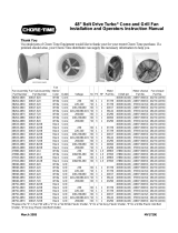
48” Belt Drive Turbo
®
with Tensioner Cone
Fan and Grill Fan
Installation and Operators Instruction Manual
MV1892HNovember 2018

Limited Warranty Installation and Operators Instruction Manual
2
MV1892H
Chore-Time Group, a division of CTB, Inc. (“Chore-Time”) warrants the new CHORE-TIME Turbo Fans
®
manufactured by Chore-
Time to be free from defects in material or workmanship under normal usage and conditions, for One (1) year from the date of
installation by the original purchaser (“Warranty”). Chore-Time provides for an extension of the aforementioned Warranty period
(“Extended Warranty Period”) with respect to certain Product parts (“Component Part”) as set forth in the table below. If such a defect
is determined by Chore-Time to exist within the applicable period, Chore-Time will, at its option, (a) repair the Product or Component
Part free of charge, F.O.B. the factory of manufacture or (b) replace the Product or Component Part free of charge, F.O.B. the factory of
manufacture. This Warranty is not transferable, and applies only to the original purchaser of the Product.
CONDITIONS AND LIMITATIONS
THIS WARRANTY CONSTITUTES CHORE-TIME’S ENTIRE AND SOLE WARRANTY AND CHORE-TIME EXPRESSLY
DISCLAIMS ANY AND ALL OTHER WARRANTIES, INCLUDING, BUT NOT LIMITED TO, EXPRESS AND IMPLIED
WARRANTIES, INCLUDING, WIHTOUT LIMITATION, WARRANTIES AS TO MERCHANTABILITY OR FITNESS FOR
PARTICULAR PURPOSES. CHORE-TIME shall not be liable for any direct, indirect, incidental, consequential or special damages
which any purchaser may suffer or claim to suffer as a result of any defect in the Product. Consequential or Special Damages as used
herein include, but are not limited to, lost or damaged products or goods, costs of transportation, lost sales, lost orders, lost income,
increased overhead, labor and incidental costs, and operational inefficiencies. Some jurisdictions prohibit limitations on implied
warranties and/or the exclusion or limitation of such damages, so these limitations and exclusions may not apply to you. This warranty
gives the original purchaser specific legal rights. You may also have other rights based upon your specific jurisdiction.
Compliance with federal, state and local rules which apply to the location, installation and use of the Product are the responsibility of
the original purchaser, and CHORE-TIME shall not be liable for any damages which may result from non-compliance with such rules.
The following circumstances shall render this Warranty void:
• Modifications made to the Product not specifically delineated in the Product manual.
• Product not installed and/or operated in accordance with the instructions published by the CHORE-TIME.
• All components of the Product are not original equipment supplied by CHORE-TIME.
• Product was not purchased from and/or installed by a CHORE-TIME authorized distributor or certified representative.
• Product experienced malfunction or failure resulting from misuse, abuse, mismanagement, negligence, alteration, accident, or lack
of proper maintenance, or from lightning strikes, electrical power surges or interruption of electricity.
• Product experienced corrosion, material deterioration and/or equipment malfunction caused by or consistent with the application of
chemicals, minerals, sediments or other foreign elements.
• Product was used for any purpose other than for the care of poultry and livestock.
The Warranty and Extended Warranty may only be modified in writing by an officer of CHORE-TIME. CHORE-TIME shall have no
obligation or responsibility for any representations or warranties made by or on behalf of any distributor, dealer, agent or certified
representative.
Effective: April, 2014
Limited Warranty
Component Part Extended Warranty Period
RXL Fan (except motors and bearings)
Three (3) Years
TURBO® Fan (except motors and bearings) Three (3) Years
TURBO® Fan fiberglass housing, polyethylene cone, and cast aluminum blade. Lifetime of Product
TURBO® fan motor and bearings. Two (2) Years
Chore-Time® Poultry Feeder Pan Three (3) Years
Chore-Time® Rotating Centerless Augers (except where used in applications involving high
moisture feed stuffs exceeding 17%)
Ten (10) Years
Chore-Time Steel Auger Tubes Ten (10) Years
ULTRAFLO® Breeder Feeding System auger and feed trough. Five (5) Years
ULTRAPAN® Feeding System augers. Five (5) Years

Installation and Operators Instruction Manual Safety
MV1892H
3
Carefully read all safety messages in this manual and on your equipment safety signs. Follow recommended
precautions and safe operating practices. Keep safety signs in good condition. Replace missing or damaged safety
signs.
Decal Descriptions
Danger: Electrocution Hazard
Disconnect electrical power before inspecting or servicing equipment unless
maintenance instructions specifically state otherwise. Ground all electrical
equipment for safety. All electrical wiring must be done by a qualified electrician
in accordance with local and national electric codes. Ground all non-current
carrying metal parts to guard against electrical shock. With the exception of motor
overload protection, electrical disconnects and over current protection are not
supplied with the equipment.
DANGER : Rotating Fan Blade
Keep Hands away. Disconnect power before servicing. Fan may start
automatically. Do not operate the Fan without the screens in place.
Disregard to the above mentioned Danger may cause serious injury including
death.
• Keep all Safety Signs and decals in good condition. Replace damaged or missing
decals.
Planning the layout of the spacing between fans is very
important. Spacing too close together will cause
interference with the flanges. Allow a minimum of 12"
between framed openings of adjacent fans.
Safety
Fan and Fan Framing Dimensions
Slant Wall Fan
Item Description
1 58” [147.32 cm]
2 55” [139.70 cm]
3 50.25” [127.63 cm]
4 8" [20.32 cm]
5 48.5” [123.2 cm]
6 64.5" [163.83 cm]
MV1700-003 03/02
Spacing Between
Framed Openings 12"
2

Installation Installation and Operators Instruction Manual
4
MV1892H
Insert the Fan Assembly in the wall opening and secure using the (12) 1/4 x 1-3/4 Lag Screws, (6) Shutter
Clips, and (6) Nylon Washers provided. The Shroud is pre-drilled. The hardware must be installed as
shown in the Figure below. This allows for rotation of the Shutter Clips when installing Shutter.
Installation
Key Description Part No.
1 1/4 x 1-3/4 SS Lag Screw 41561
2 Shutter Clip 36729
3 Nylon Washer 4856
32
1

Installation and Operators Instruction Manual Installation
MV1892H
5
Installing the Cone and Grill to the Fiberglass Fan
1. Slide the Cone onto the Shroud—the Shroud fits inside the Cone. (See Figure below)
4" slots are cut into the edge of the cone to allow expansion as the Cone is slid onto the Shroud.
2. Align the holes in the Shroud with the slots in the Cone.
3. Insert the (6) Wafer Head Bolts from inside the Shroud through the Cone and thread the Flange Nuts onto ends of
the Wafer Head Bolts.
4. Snap the Cone Grill into the slots on the outlet end of the Cone.
Removing Wire Tie and Installing Belt
1.Cut and remove Wire Tie from Driven Sheave (See Figure below).
2.Install Belt as shown.
2
5
4
3
4
1
Key Description Part No.
1 Shroud (White) 37914
Shroud (Black Interior) 46631
2 1/4-20 SS Hex Ser. Flange Nut 46298
3 Cone Grill 35199
4 Cone (White) 38268
Cone (Black) 46630
5 1/4-20 x 7/8 Wafer Head Bolt 40775
Belt
Wire Tie

Shutter Installation/Cord Routing and Wiring Installation and Operators Instruction Manual
6
MV1892H
1.See Wiring diagram on Motor for Motor electrical connections. Follow local, state, and national electrical codes
for wiring
2.Install an electrical disconnect within reach of each Fan.
3.Route the motor cord (not supplied) toward the upper left corner of the Fan and attach the cord to the Motor
Mount using the three Cable Ties—included in the hardware package.
4.Cut a 3/8" [9.53 mm] slot in the upper left flange of the Shutter frame in order to route the electrical cord out the
back.
5.Position the Shutter, centered in the Fan Shroud, and rotate the Shutter Clips to lock the Shutter into place. Check
the Shutter for proper operation. The Shutter must be able to open and close freely without obstructions.
6.Some installations may require an exit hole for the motor cord to be drilled in the side of the Shroud. These
installations must have electrical wires routed through conduit.
Note:Make sure the conduit or wires do not interfere with the Fan Blades or Shutter operation.
Shutter Installation/Cord Routing and Wiring
Key Description
1 Shroud
2 Shutter
3 Shutter Clip
4 3/8" Slot to Route Motor Cord
1
2
3
4

Installation and Operators Instruction Manual Maintenance
MV1892H
7
•Disconnect Power Prior To Maintaining Or Cleaning The Fan. The fan may start automatically causing serious injury
or death.
• Service and repair of fans should be done only by a qualified technician.
• Keep the fan clean for maximum life and best performance. Avoid spraying water on fan shaft bearings.
• Periodically check the V-Belt and replace if necessary. A bad Belt will cause a substantial drop in Fan performance or
it can break and cause Fan failure. If a Belt rides below the Sheave edge, replace the Belt. (See Figure Below)
• Keep Shutters, Blades, and Housing clear of obstacles for best air performance.
• Check Sheaves for wear. Replace if Sheave groove is
worn.
(See Figure to the Right).
•Check Belt Tension. The Belt should be tensioned just
tight enough to minimize Belt slippage. Over tension
-
ing the belt will cause premature Belt and Bearing wear.
With a new Belt, the notches on the outside wheel
(Item 1, below) of the Tensioner should line up with
the mark on the inside wheel (Item 2) of the Tensioner
based on the chart below.
Maintenance
Worn Sheave
(Needs Replaced)
Good Belt Bad Belt
Good Sheave
Bad Sheave
Bad Belt
(Needs Replaced)
1
2
3
4
"4th Notch"
"3-1/2 Notch"
1
2
1
2
1
2
"5th Notch"
Fan Model Number
(see chart for correct Tensioner
positioning with belt installed)
"3rd Notch"
1
2
3
4
1
2
1
2
3
4
5
5
1
2
3
4
5
Fan Part No. Tensioner Position
50232-32X Series
"3rd Notch"
50232-52X Series
50232-92X Series
50232-22X Series "3-1/2 Notch"
50232-42X Series
50232-72X Series
50232-82X Series
50232-21X Series "4th Notch"
50232-51X Series "5th Notch"
50232-41X Series
Item Description
1 Outside wheel on Tensioner
2 Inside wheel on Tensioner

Maintenance Installation and Operators Instruction Manual
8
MV1892H
Fan Bearing and Belt Tensioner Lubrication
• Grease zerks are provided for lubrication on the fan shaft bearings and the belt tensioner.
• Lubricate the fan every 2-6 months or whenever these components get wet.
• Disconnect power to the fan before lubricating.
• Clean the zerk before lubricating to prevent contamination from entering the bearing.
• Use a high quality lithium based, NLGI #2, grease such as Shell Gadus S2 V100 2. Do not use incompatible greases
containing aluminum, barium, calcium, bentonite clay or polyurea thickeners.
• Slowly rotate the fan shaft by hand while slowly applying the grease. Rapidly applying grease to a stationary bearing
can damage the bearing seals.
• Apply about .10 oz (2.8 g, 3.1 cc) of grease at a time or until a slight amount of grease can be seen purging from the
seal.
Grease Zerk
Grease Zerk
Note: Some Parts removed for Clarity

Installation and Operators Instruction Manual Part Numbers
MV1892H
9
Fan Assembly Part Numbers
Part Numbers
*Replace the "X" in Fan P/N with a "2" for a Flat White Plastic Shutter, "4" for a Flat Gray Plastic Shutter, "5" for
a White Plastic Inlet Bell Shutter, "6" for Gray Plastic Inlet Bell Shutter, "B" for Black Shroud Interior.
Fan A ss embly
Part Number
Fan Sub-
Assembly Part
Number
Fan
Inter ior
Color Outlet Voltage Hz Ph HP
Moto r
Par t
No. V-Belt p/n
Motor sheave
Part No.
Fan sheave
Part No.
38264-480X 50232-02X White Cone -- -- -- -- --
50271 (AX49)
24697 (AK32) 40274 (AK94)
38264-482X 50232-22X White Cone 230 60 1 1 37729
50271 (AX49)
24697 (AK32) 40274 (AK94)
38264-483X 50232-32X White Cone 220-240 50 1 1 37729
50270 (AX48)
37919 (AK34) 28143 (AK84)
38264-484X 50232-42X White Cone 208-230/460 60 3 1 40157
50271 (AX49)
24697 (AK32) 40274 (AK94)
38264-485X 50232-52X White Cone 220-240/380-415 50 3 1 48608
50270 (AX48)
37919 (AK34) 28143 (AK84)
38264-487X 50232-72X White Cone 200/400 60 3 1 43290
50271 (AX49)
24697 (AK32) 40274 (AK94)
38264-488X 50232-82X White Cone 208-230/460 60 3 1 44694
50271 (AX49)
24697 (AK32) 40274 (AK94)
38264-489X 50232-92X White Cone 200/400 50 3 1 43290
50270 (AX48)
37919 (AK34) 28143 (AK84)
38264-484XS 50232-42XS White Cone 208-230/460 60 3 1 40157
50271 (AX49)
24697 (AK32) 40274 (AK94)
46633-480X 50232-02XB Black Cone -- -- -- -- --
50271 (AX49)
24697 (AK32) 40274 (AK94)
46633-482X 50232-22XB Black Cone 230 60 1 1 37729
50271 (AX49)
24697 (AK32) 40274 (AK94)
46633-482XS 50232-22XBS Black
B
lack Con
e
230 60 1 1 37729
50271 (AX49)
24697 (AK32) 40274 (AK94)
46633-482XS
W
50232-22XBS Black
W
hite Con
e
230 60 1 1 37729
50271 (AX49)
24697 (AK32) 40274 (AK94)
46633-483X 50232-32XB Black Cone 220-240 50 1 1 37729
50270 (AX48)
37919 (AK34) 28143 (AK84)
46633-484X 50232-42XB Black Cone 208-230/460 60 3 1 40157
50271 (AX49)
24697 (AK32) 40274 (AK94)
46633-485X 50232-52XB Black Cone 220-240/380-415 50 3 1 48608
50270 (AX48)
37919 (AK34) 28143 (AK84)
46633-487X 50232-72XB Black Cone 200/400 60 3 1 43290
50271 (AX49)
24697 (AK32) 40274 (AK94)
46633-488X 50232-82XB Black Cone 208-230/460 60 3 1 44694
50271 (AX49)
24697 (AK32) 40274 (AK94)
46633-489X 50232-92XB Black Cone 200/400 50 3 1 43290
50270 (AX48)
37919 (AK34) 28143 (AK84)
46633-484XS 50232-42XBS Black
B
lack Con
e
208-230/460 60 3 1 40157
50271 (AX49)
37919 (AK34) 40274 (AK94)
46633-484XS
W
50232-42XBS Black
W
hite Con
e
208-230/460 60 3 1 40157
50271 (AX49)
37919 (AK34) 40274 (AK94)
47898-482X 50232-21X White Cone 230 60 1 1.5 49903
50270 (AX48)
24697 (AK32) 28143 (AK84)
47898-484X 50232-41X White Cone 208/230-460 60 3 1.5 47693
50270 (AX48)
24697 (AK32) 28143 (AK84)
47898-485X 50232-51X White Cone 200 50 3 1.5 50347
50270 (AX48)
24697 (AK32)
49811 (AK69)
47943-482X 50232-21XB Black Cone 230 60 1 1.5 49903
50270 (AX48)
24697 (AK32) 28143 (AK84)
47943-484X 50232-41XB Black Cone 208/230-460 60 3 1.5 47693
50270 (AX48)
24697 (AK32) 28143 (AK84)
38948-480X 50232-02X White Grill -- -- -- -- --
50271 (AX49)
24697 (AK32) 40274 (AK94)
38948-482X 50232-22X White Grill 230 60 1 1 37729
50271 (AX49)
24697 (AK32) 40274 (AK94)
38948-483X 50232-32X White Grill 220-240 50 1 1 37729
50270 (AX48)
37919 (AK34) 28143 (AK84)
38948-484X 50232-42X White Grill 208-230/460 60 3 1 40157
50271 (AX49)
24697 (AK32) 40274 (AK94)
38948-485X 50232-52X White Grill 220-240/380-415 50 3 1 48608
50270 (AX48)
37919 (AK34) 28143 (AK84)
38948-487X 50232-72X White Grill 200/400 60 3 1 43290
50271 (AX49)
24697 (AK32) 40274 (AK94)
46750-480X 50232-02XB Black Grill -- -- -- -- --
50271 (AX49)
24697 (AK32) 40274 (AK94)
46750-482X 50232-22XB Black Grill 230 60 1 1 37729 50271 (AX49) 24697 (AK32) 40274 (AK94)
46750-483X 50232-32XB Black Grill 220-240 50 1 1 37729 50270 (AX48) 37919 (AK34) 28143 (AK84)
46750-484X 50232-42XB Black Grill 208-230/460 60 3 1 40157
50271 (AX49)
24697 (AK32) 40274 (AK94)
46750-485X 50232-52XB Black Grill 220-240/380-415 50 3 1 48608
50270 (AX48)
37919 (AK34) 28143 (AK84)
46750-487X 50232-72XB Black Grill 200/400 60 3 1 43290
50271 (AX49)
24697 (AK32) 40274 (AK94)

Part Numbers Installation and Operators Instruction Manual
10
MV1892H
Fan Part Numbers

Installation and Operators Instruction Manual Part Numbers
MV1892H
11
Shutter Part Numbers
Item Description Part No.
16** Sheave Varies**
17** Grip Notch V-Belt Varies**
18** Motor Sheave Varies**
19
Shutter Clip
36729
20 1" Shaft 39688
21 1" Pillow Block Bearing 50553
22 Outlet Cone (White) 38268
Outlet Cone (Black) 46630
23 1/4x1-1/8 Sq. Key 2419-2
24 1/4-20x1.00 SS Hx Hd Bolt 4404-11
25 Motor Mount Connector Angle 47877
26 48" Turbo
®
Fan Motor Mount Brace 39710
27
Idler with Bushings (For Repair) 50879
* See “Shutter Part Numbers” below
**See “Fan Assembly Part Numbers” on page 9
Turb o
®
Fan Part Numbers
Item Description Part No.
1** Motor Varies**
2 3.5" Arm 3" Dia. Tensioner Assembly 48429
3 48" Tensioner Bracket 50233
4 Fiberglass Fan Shroud Grill 37921
5 Upper Motor Mount Support 50266
6 Fan Shroud (White) 37914
Fan Shroud (Black Interior) 46631
7 Danger Decal 2527-50
8 48" Cast Aluminum Fan Blade 38903
9 Lower Motor Mount Support 37732
10 48" Fan Motor Mount 50267
11 1" Taper Lock Hub 38909
12* 48" Shutter Varies*
13 Identification Decal Varies
14 Cone Grill 35199
15 Chore-Time Decal 2525-4
MV1700-016 03/02
1
4
3
4
5
2
6
Item Description Part No.
1 Belled Plastic Shutter (White) 48291
Belled Plastic Shutter (Gray) 48296
2 Flat Plastic Shutter (White) 38029
Flat Plastic Shutter (Gray) 46716
3 Push Nut 1/4'' 38032
4 Shutter Pivot Rod 38702-4
5 Shutter Louver (White) 38038-4
Shutter Louver (Gray) 46715-4
6 Shutter Clip 36729

Part Numbers Installation and Operators Instruction Manual
12
MV1892H
MADE TO WORK.
BUILT TO LAST.
®
Note: The original, authoritative version of this manual is the English version produced by CTB, Inc. or any of its
subsidiaries or divisions, (hereafter collectively referred to as "CTB"). Subsequent changes to any manual made by
any third party have not been reviewed nor authenticated by CTB. Such changes may include, but are not limited
to, translation into languages other than English, and additions to or deletions from the original content. CTB
disclaims responsibility for any and all damages, injuries, warranty claims and/or any other claims associated with
such changes, inasmuch as such changes result in content that is different from the authoritative CTB-published
English version of the manual. For current product installation and operation information, please contact the
customer service and/or technical service departments of the appropriate CTB subsidiary or division. Should you
observe any questionable content in any manual, please notify CTB immediately in writing to: CTB Legal
Department, P.O. Box 2000, Milford, IN 46542-2000 USA.
Revisions to this Manual
Page No. Description of Change ECO
33685
Various Show 6 Screen Clips instead of 4 and 1 Washer per Screen Clip instead of 2.
Moved Fan Assembly Part numbers to back.
Moved Shutter part numbers to back
Moved Warranty and Safety to front of manual
For additional parts and information, contact your nearest Chore-Time distributor or representative.
Find your nearest distributor at: www.choretime.com/contacts
Chore-Time Group, A division of CTB, Inc.
PO Box 2000
Milford, Indiana 46542-2000 USA
Phone (574) 658-4101 Fax (877) 730-8825
Email: [email protected]m
Internet: www.choretime.com
/