Page is loading ...

The Ultimate Connection
Continental
®
Continental Industries, Inc. Tel. 800.558.1373 www.conind.com
4102 S 74th East Ave Tel. 918.627.5210 www.thermoweld.com
GAS • PROPANE • PLUMBING • WATER DISTRIBUTION • CATHODIC PROTECTION
34-6034-12
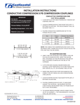
CON-STAB PE X COPPER TRANSITION COUPLINGS
Installation Instructions
1. Cut copper tubing end square and remove all burrs.
2. Clean tubing thoroughly to assure there is no dirt, grease or oil in assembly area.
3. Check the tubing surface within 1" from the end to ensure it is smooth and free of scratches. If
surface is not smooth or scratches exist, recut tubing to eliminate damaged area.
4. Remove compression nut from the tting and slide the nut onto the copper tubing.
5. Flare copper tubing end to 45° using aring tool.
6. Slide the compression nut up to the are and thread onto the tting nger-tight. (In the case of
slight side loads which may exist during assembly, it may be necessary to "snug up" the mating parts
with a wrench to achieve a nger-tight condition.)
7. To provide a leak tight joint, tighten compression nut 1/4 turn past nger-tight.
8. Leak test assembled joint.
ECN 2241 REV "K" 11/18/08

ASSEMBLY INSTRUCTIONS : I.D. SEAL
®
CON-STAB
Repeat steps 1 thru 8 for all Con-Stab joints.
9
To assure proper assembly and to comply with
49 CFR 192 Subpart J—Test Requirements, the
joint shall be leak tested.
10
Cut pipe ends square.
2
Clean piping thoroughly
to assure there is no dirt,
grease or oil in assembly
area.
3
Chamfer end of pipe
using Continental's
ID chamfering tool with ID
gauge.
or
4a
Chamfer end of pipe
using Continental's
double ended ID chamfering
tool.
4b
Verify the stab fitting
is the correct size for
the polyethylene (P.E.)
pipe. Verify the SDR (or
wall thickness) of the pipe matches the SDR (or wall
thickness) printed on the tting label.
1
If using ID chamfer tool
with gauge, check for
proper chamfer by inserting
pipe on gauge up to the o
ring. With proper chamfer,
o ring will begin to enter
pipe.
6
Proper Chamfer
Improper Chamfer
Mark the stab depth by
inserting pipe into ID
chamfer tool and marking
the pipe at the entrance as
shown.
5
Stab pipe completely
into tting entrance.
7
Stab pipe completely
into fitting so that
the mark on the pipe is
within 1/8" from the tting
entrance.
8
IMPORTANT
CHAMFER THE
ID OF PIPE
P
.E
.
P
i
p
e
IMPORTANT
For use on:
Polyethylene gas pipe meeting the requirements of
ASTM D 2513
Pressure Rating: 125 psig MAOP
Operating Temperature: -20 to 140° F
/


