Page is loading ...

The Ultimate Connection
CONTINENTAL INDUSTRIES
The Ultimate Connection
34-6034-36
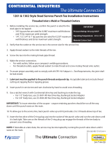
1214, 1315, 1416 & 1517 STYLE TRANSITION SADDLE TEE
INSTALLATION INSTRUCTIONS
1" IPS & Smaller Steel Mains X Con-Stab ID Seal® Transition
1. Before installing the service tee, conrm the punch is rated for the steel
pipe to be tapped.
• 3/8" tip punches are rated for 0.280" maximum wall thickness
and 70 ksi maximum yield strength.
• 1/4", 1/2", 3/4" & 1" tip punches are rated for 0.250" maximum
wall thickness and 65 ksi maximum yield strength.
2. Verify that the outlet on the transition tee is the correct size for the
service line.
3. Clean the main of all coatings, rust, dirt, etc., in the area where the
saddle is to be installed. The elastomer seal should not be installed over
pits or gouges in the pipe where the sealing integrity might be compromised.
4. Remove saddle bolt and place saddle in the desired position.
5. Replace saddle bolt and tighten leak tight, taking care not to rotate saddle on the main. It is recommended that
the bolt be tightened to 25 foot pounds of torque.
DO NOT OVER TORQUE BOLT.
6. Make the service connection. See back of this sheet for P.E. Con-Stab outlets.
7. To assure proper assembly and to comply with 49 CFR 192 Subpart J—Test Requirements, the joint shall be leak
tested.
8. Remove pipe cap and punch.
9 . Lubricant must be applied to the punch threads and punch tip. Acceptable lubricants include thread cutting
oil, tapping uid or tapping grease.
10. Insert punch in transition tee and turn clockwise by hand to avoid cross threading.
11. Use a ratchet wrench with Continental drive key and bushing to make the tap.
• For 1/2" body tees, use 23-3691-00 Hex Drive Key, Bushing & Socket Adapter
• For 3/4" body tees, use 23-3692-00 Hex Drive Key, Bushing & Socket Adapter
• For 1" body tees, use 23-0941-00 Square Drive Key, Bushing & Socket Adapter
• For 1 1/4" body tees, use 23-0940-00 Square Drive Key, Bushing & Socket Adapter
IMPORTANT: To insure retention of the coupon - coupon retaining punches should be run all the way down until the
punch seats on the main.
12. To allow gas to the service line, back punch up until it is ush with the top of the tee.
13. Apply thread sealant and install pipe cap leak tight.
NOTE: If desirable at a later date, the service may be interrupted by running the punch valve down until it seats on the
main.
NOTE: It is advisable to limit shear at main connections. In this regard, your company's policies should be followed.
For further information, reference; ASTM D 2774 Standard Practice for Underground Installation of Thermoplastic
Pressure Piping; Code of Federal Regulations, Title 49, Transportation Part 192; AGA Plastic Pipe Manual and/or The
Guidance Manual for Operators of Small Gas Systems by the U.S. Department of Transportation.
ECN 2625 REV "V" 08/25/14
IMPORTANT
Pressure Rating: Designed to meet or
exceed pressure rating of PE pipe per
49 CFR Part 192 and ASTM D 2513
Operating Temperature: -20 to 140° F
For Use With: Natural Gas or Propane

NOTE: It is advisable to limit shear at main connections. In
this regard, your company’s policies should be followed.
For further information, reference; ASTM D 2774 Standard
Practice for Underground Installation of Thermoplastic
Pressure Piping; Code of Federal Regulations, Title 49,
Transportation Part 192; AGA Plastic Pipe Manual and/or
The Guidance Manual for Operators of Small Gas Systems
by the U.S. Department of Transportation.
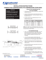
ASSEMBLY INSTRUCTIONS : I.D. SEAL® CON-STAB
Repeat steps 1 thru 8 for all Con-Stab joints.
9
To assure proper assembly and to comply with
49 CFR 192 Subpart J—Test Requirements, the
joint shall be leak tested.
10
Cut pipe ends square.
2
Clean piping thoroughly
to assure there is no dirt,
grease or oil in assembly
area.
3
Chamfer end of pipe
using Continental's
ID chamfering tool with ID
gauge.
or
4a
Chamfer end of pipe
using Continental's
double ended ID chamfering
tool.
4b
Verify the stab fitting
is the correct size for
the polyethylene (P.E.)
pipe. Verify the SDR (or
wall thickness) of the pipe matches the SDR (or wall
thickness) printed on the tting label.
1
If using ID chamfer tool
with gauge, check for
proper chamfer by inserting
pipe on gauge up to the o
ring. With proper chamfer, o
ring will begin to enter pipe.
6
Proper Chamfer
Improper Chamfer
Mark the stab depth by
inserting pipe into ID
chamfer tool and marking
the pipe at the entrance as
shown.
5
Stab pipe completely
into tting entrance.
7
Stab pipe completely
into fitting so that
the mark on the pipe is
within 1/8" from the tting
entrance.
8
IMPORTANT
CHAMFER
THE
ID OF PIPE
P
.E
.
P
ip
e
IMPORTANT
For use on:
Polyethylene gas pipe meeting the requirements of ASTM
D 2513
Pressure Rating: Designed to meet or exceed pressure rat-
ing of PE pipe per 49 CFR Part 192 and ASTM D 2513
Operating Temperature: -20 to 140° F
/


