Broan ERVS100S Installation guide

Type
Installation guide

The Broan ERVS100S Energy Recovery Ventilator is an efficient, whole-house ventilation solution that provides fresh, filtered air while removing stale, humid air. It features a compact design that can be installed in the ceiling, attic, or under the ceiling in a living area. With its ability to connect to a Standby switch or Broan VB20W 20-minute push-button control, you can customize your ventilation needs.

The Broan ERVS100S Energy Recovery Ventilator is an efficient, whole-house ventilation solution that provides fresh, filtered air while removing stale, humid air. It features a compact design that can be installed in the ceiling, attic, or under the ceiling in a living area. With its ability to connect to a Standby switch or Broan VB20W 20-minute push-button control, you can customize your ventilation needs.

4
2 Unit Preparation
Inspect the exterior of the unit for shipping damage.
Unit should never operate while the building is still in construction.
Unit is shipped with its door covered with a cardboard for protection during construction. Leave the cardboard on until painting.
3 Installation
3.1 Positioning the Unit
Unit can be installed between 24” on-center trusses, on top of 24” on-center trusses or under the ceiling, using brackets. A set
of 4 brackets is included in the hardware kit, along with the necessary screws.
A standard 3-prong electrical outlet has to be available within 28” of the unit and must be connected to its own dedicated circuit.
Allow a 12” clearance for the door, core and filters to be removed for maintenance.
3.1.1 Installation in the ceiling (between 24 on-center trusses)
1. Trace a level line on both trusses, at 1/2” or 1” from the bottom, for
the unit bracket location (1/2” will allow the unit door perimeter to
lay on ceiling material while 1” will result in flush mount installation;
see A and B in next page). On one truss, screw half way on level line
two no. 8 x 1½” provided screws, leaving 23” between each other.
2. Mount the 4 brackets to the unit as illustrated at right,
using two no. 10 x 5/8" screws provided for each
bracket.
TIP: Screw half way the screws to allow adjusment
between trusses, see insets at right (left shows the
minimum distance and right the maximum distance.
3. Hang the lightest side of the unit on the screws mounted on
the truss using the larger holes of the brackets.
4. Lift the other side of the unit and secure it to the other truss
using one no. 8 x 1½” screw per bracket, inserted through
the smaller hole of the brackets.
VD0391A
VD0394
VD0390
5
3.1.1 Installation in the ceiling (between 24 on-center trusses)
(cont'd)
5. Secure the first brackets installed to the truss using one no. 8 x 1½” screw per
bracket, inserted through their smaller hole, then tighten completely the brackets
screws to the unit.
6. Spread the insulation over the unit (and around, as for B at right).
3 Installation (cont'd)
3.1 Positioning the Unit (cont'd)
VD0393
VD0386
1/2”
1”
A
B
1/2" CEILING MATERIAL
INSULATION
(OVER AND AROUND
THE UNIT)
INSULATION
(OVER AND AROUND
THE UNIT)
CAUTION
When installed in the attic, insulation must be spread over the
unit.
6
3 Installation (cont'd)
3.1 Positioning the Unit (cont'd)
VH0111
DOOR
NO. 10 X 5/8"
NO. 8 X 1½"
3.1.2 Installation in the attic (unit having its door on top)
1. Rotate the backdraft damper 180° (no tool required) so that it falls in closed position and the word "TOP" engraved on the
damper is up once the unit is in place.
2. Mount the brackets to the unit as illustrated below using two no. 10 x 5/8" screws provided for each bracket.
3. Secure the unit to the trusses using one no. 8 x 1½" screw provided for each bracket.
4. IMPORTANT: If the attic is not ventilated and without radiant barrier sheathing, insulation material must be added around and
over the unit. Ensure access is kept for product maintenance.
3.1.3 Installation under the ceiling (in a living area)
9¼”
VD0385
24"-DEEP CLOSET
1. Mount the brackets to the unit as illustrated above using two no. 10 x 5/8”
screws provided for each bracket.
2. Secure unit to the ceiling using two no. 8 x 1½” screws provided for each
bracket, making sure not to secure it into drywall alone.
7
3.2 Combining with an AHU
3.2.1 Recommended configurations
When the distribution of fresh air from the ERV is connected to the return of an AHU (such as in the image below, on the left),
the connection should be done as close as possible from one AHU return grille to ensure proper functionning of the built-in
fresh air damper.
3.2.2 Prohibited configurations
Distribution of fresh air from the ERV in the distribution ducting from the AHU (such as in the image below, on the left) may cause
condensation issues during cooling season and must be avoided.
Connecting both distribution of fresh air from the ERV and stale air exhaust in the AHU return ducting (such as in the image
below, on the right) must be avoided.
ERV
AHU
Stale air
to outdoors
with backdraft
damper
Return grille
of AHU
Fresh air
from outdoors
Stale air
from home
VH0114A
Return grille
of AHU
Distribution of
fresh air in AHU
Stale air
from home
ERV
Fresh air
from outdoors
Stale air
to outdoors
with backdraft
damper
AHU supply ducting
and grille to home
AHU
VH0112A
Stale air from home
connected to return
ducting of AHU
Distribution
of fresh air
using plastic grille
AHU
AHU supply ducting
and grille to home
Stale air
to outdoors
with backdraft
damper
Fresh air
from outdoors
VH0113A
ERV
OPTION 2OPTION 1
3 Installation (cont'd)
ERV
AHU supply ducting
and grille to home
Stale air from home
connected to return
ducting of AHU
Distribution
of fresh air
connected to return
ducting of AHU
Stale air
to outdoors
with backdraft
damper
Fresh air
8
3 Installation (cont'd)
3.3 Installing the Registers, Ductwork and Hoods
3.3.1 Registers
Refer to applicable building codes to plan where the stale air exhaust registers and fresh air distribution registers should be
installed. Below are some general recommendations.
Stale air exhaust registers:
Install the stale air exhaust registers where the contaminants are produced: bathroom (up to 2), kitchen, living room, etc.
Position the registers as far from the stairway as possible and in such a way that the air circulates in all the lived-in spaces in
the house.
If a register is installed in the kitchen, it must be located at least 4 feet away from the cooking applicances.
Install the registers on an interior wall, 6 to 12 inches below the ceiling OR in the ceiling.
Fresh air distribution registers (Option 2 in 3.2.1):
Install the fresh air distribution registers in bedrooms, dining rooms, living rooms and basement, if applicable.
Keep in mind that the fresh air registers must be located as far as possible from the ERV stale air registers.
Install the registers on an interior wall, 6 to 12 inches below the ceiling OR in the ceiling.
If a register must be floor installed, direct the airflow up the wall.
WARNING
Never install a stale air exhaust register in a closed room where a combustion device operates, such as a gas
furnace, a gas water heater or a fireplace.
!
3.3.2 Ductwork
All units ports should be connected to 6” ducts, but can be connected to larger ducts using an appropriate transition.
If you have to connect rigid ducts to the unit, use a short lenght (approximately 6”) of flexible duct to avoid transmission of
vibrations. Use a tie wrap and foil tape to connect the flexible duct to the port and to the rigid duct.
Never use screws to connect rigid ducting to the ports.
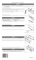
Connecting insulated flexible ducts to the ports:
1. Pull back the insulation to expose the flexible duct.
2. Attach the flexible duct to the port using a tie wrap; ensure tie wrap is tighten to its maximum strength.
3. Pull the insulation over the joint, then pull the vapor barrier (shaded part in illustrations below) over the insulation. Make sure
that the vapor barrier does not tear due to manipulation to avoid condensation within the ducts.
4. Apply foil tape to the joint, making an airtight seal. Avoid compressing the insulation when pulling the tape tightly around the
joint. Compressed insulation loses its R value and causes water dripping in cold climates due to condensation on the exterior
surface of the duct.
NOTE: If sealant mastic has to be used over the foil tape as an extra sealing layer, use water based mastic to ensure material
compatibility with the port.
WARNING
When performing duct connections, always use approved tools and materials. Respect all corresponding laws
and safety regulations. Please refer to your local building code.
!
CAUTION
If ducts have to go through an unconditioned space (e.g.: attic), always use insulated ducts.
VJ0134
TIGHTEN TIE WRAP TO ITS
MAXIMUM STRENGTH!
9
3.3.3 Hoods
Refer to applicable building codes to plan where the stale air exhaust hood and fresh air distribution hood should be installed.
Below are some general recommendations.
There must be a minimum distance of 6' between the hoods to avoid cross-contamination.
Hoods must be at least 18" above the ground.
Exhaust hood must have a backdraft damper.
WARNING
Make sure the intake hood is at least 6 feet away from any of the following:
Dryer exhaust, high efficiency furnace vent, central vacuum vent
Gas meter exhaust, gas barbecue-grill
Any exhaust from a combustion source
Garbage bin and any other source of contamination
!
3 Installation (cont'd)
3.3 Installing the Registers, Ductwork and Hoods (cont'd)
3.4 Connecting the Controls (energized by unit, low voltage)
Controls are not included with this unit.
Unit may be connected to a dry contact Standby switch if desired. In such case, unit remains powered on, but is put in Standby
mode when the switch is turned on.
• This ERV can replace up to 2 bath fans. Where this is the case, unit should be connected to a 20-minute override control in
each bathroom.
3.4.1 Connecting unit to a Standby switch
Install the dry contact Standby switch in a convenient place and connect it to unit as follows.
3.4.2 Connecting unit to 1 or 2 Broan VB20W 20-minute push-button control(s)
1. Install the 20-minute push-button control in the bathroom(s) following instructions included with the control.
2. Connect it to unit as follows.
R RED
Y YELLOW
B BLACK
G GREEN
R RED
Y YELLOW
B BLACK
G GREEN
G
R
B
Y
VE0357A
G
R
B
Y
OL
OC
I
VE0358A
OL
OC
I
ON ON
CAUTION
Ensure all unused wires are capped off.
Switch position Unit mode
Dry contact opened
Unit will run in the
selected mode
Refer to 4.1
Dry contact closed
Unit is kept in
Standby mode
10
3.4.3 Connecting unit to a Standby switch AND 1 or 2 Broan VB20W 20-minute push-button control(s)
1. Install the 20-minute push-button control in the bathroom(s) following instructions included with the control.
2. Install the Standby switch in a convenient place.
3. Connect both with the unit as follows.
3 Installation (cont'd)
3.4 Connecting the Controls (energized by unit, low voltage) (cont'd)
R RED
Y YELLOW
B BLACK
G GREEN
G
R
B
Y
OL
OC
I
BROAN VB20W
20-
MIN.
PUSH-BUTTON CONTROL
DRY CONTACT
S
TANDBY SWITCH
VE0359A
ON
ON
I
OC
OL
This connection allows the operation of VB20W push-button controls even if the dry contact standby switch is turned off.
Switch position Unit mode
Dry contact opened
Unit will run in the
selected mode
Refer to 4.1
Dry contact closed
Unit is kept in
Standby mode
3.5 Installing a Tandem
®
Transition* Kit
If desired, a Tandem transition kit can be used instead of 2 exterior hoods.
An additional backdraft damper (not included) must be installed on the stale air to
outdoors duct following common best practice. Should the backdraft damper cause
an interruption in the insulation of the stale air to outdoors duct, make sure that
insulation is added around the backdraft damper to avoid condensation.
The joist opening needed to install the Tandem
®
transition must be 9¾” minimum. The
maximum height of the Tandem transition is 8¾”.
To connect the insulated flexible ducts to the Tandem transition (Exhaust air to
outdoors and Fresh air from outdoors), follow the instructions included with the
Tandem transition kit (part no. VTYIK1).
*Patented.
VR0003
Tandem transition kit
CAUTION
If using a Tandem Transition, a backdraft damper must be installed on the stale air to outdoors duct. If this causes an
interruption in the duct insulation, insulation must be added around the backdraft damper to avoid condensation.
  • Page 1 1
  • Page 2 2
  • Page 3 3
  • Page 4 4
  • Page 5 5
  • Page 6 6
  • Page 7 7

Broan ERVS100S Installation guide

Type
Installation guide

The Broan ERVS100S Energy Recovery Ventilator is an efficient, whole-house ventilation solution that provides fresh, filtered air while removing stale, humid air. It features a compact design that can be installed in the ceiling, attic, or under the ceiling in a living area. With its ability to connect to a Standby switch or Broan VB20W 20-minute push-button control, you can customize your ventilation needs.

Ask a question and I''ll find the answer in the document

Finding information in a document is now easier with AI