Page is loading ...


Sargent Electrical Services Ltd. 2005
AC75&50 Control Panels - Issue 5 (connection data).docPage 2 of 3 10/10/2005
AC50 and AC75 Operation (when fitted to SG product)
Symbol Function Description
12v Power On / OFF This switch turns on (or off) the 12-volt power to all circuits.
Note: as this switch works in conjunction with a relay (that uses
around 40mA to operate), it should only be used for relatively
short periods of time while using the caravan (i.e. when going
out for the day).
For long-term isolation of the12 volt power, please place the Car
/ Van selector switch on the ESM2004 power supply unit in the
centre (Off) position (i.e. during storage).
Entry light This switch operates the internal entry light (usually the first light
within the caravan).
AC50
Only
Water Pump This switch turns on power to the water pump ready for use. It
can be used to turn off the pump over night to avoid any noise
from the pump (down on, up off).
Note: A green indicator lamp will illuminate within the bottom left
corner of the battery gauge when the pump motor is running.
AC75
Only
Dual Pumps In caravans with an onboard water tank, the pump switch will be
a two-way switch with a centre off position. This allows the
selection of either the internal pump (switch up – Tap symbol) or
external pump (switch down – Water container symbol).
Note: A green indicator lamp will illuminate within the bottom left
corner of the battery gauge when the internal pump motor is
running.
Battery Level test This switch is used to display the battery voltage level. Press
and hold the switch to display the battery level on the gauge.
The green region indicates a battery with a good charge, the
yellow region indicates a battery with an adequate charge, and
the red region indicates a battery that requires charging.
Water Level test This switch is used to display the fresh water level within the
onboard water tank. Press and hold the switch to display the
water level on the gauge.
The gauge indicates the water level on an ‘Empty - ¼ - ½ - ¾ -
Full’ scale, with empty being on the left.
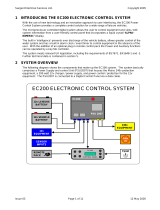
When using the optional remote control unit, please ensure the control panel ‘12v Power’
switch is in the ON position and the ‘Entry light’ switch is in the OFF position for correct
operation of the remote control (as the remote control operates in parallel with the control
panel switches). The remote control button [I] controls the Entry Light and button [II]
controls the 12v Power.
If you do not wish to use the remote control, or the remote battery is flat / remote has
been lost, you can of course return to manual operation by using the switches on the
control panel. If the power has been turned off using the remote control and then the
remote has been lost / battery become flat you will need to carry out the following to
reset the caravan: Place the Car / Van selector switch on the ESM2004 power supply
unit in the centre (OFF) position and turn the charger switch to the OFF position, wait 5
seconds and then turn the charger & Car / Van selector switch back on.
The UH**** number on the back of the remote control is the remote code number.
Please keep a record of this number in case you need to order a replacement or
additional remote control.
+
-
PDF created with pdfFactory trial version www.pdffactory.com

Sargent Electrical Services Ltd. 2005
AC75&50 Control Panels - Issue 5 (connection data).docPage 3 of 3 10/10/2005
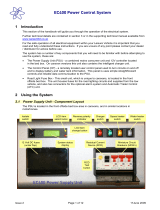
AC50 and AC75 Connection Data
Note: Pins 1 & 10 are not used on the AC50 panel
51 2 3 4
6 7 8 9
11 12 13 14
10
15
OUTPUT
51 2 3 4
6 7 8 9
11 12 13 14
10
15
51 2 3 4
6 7 8 9
11 12 13 14
10
15
OUTPUT
Water Level Sensor Feed10Internal Pump2
--12v Supply8
Spare15Power / EMC Relay Feed7
Spare14Spare6
Spare1312v Supply5
Spare12Awning / Entry Light4
Negative Supply11Pump Switch Feed3
Water Level Signal9External Pump1
Water Level Sensor Feed10Internal Pump2
--12v Supply8
Spare15Power / EMC Relay Feed7
Spare14Spare6
Spare1312v Supply5
Spare12Awning / Entry Light4
Negative Supply11Pump Switch Feed3
Water Level Signal9External Pump1
View looking at mating face
of control panel connector
(or rear face of harness
connector).
PDF created with pdfFactory trial version www.pdffactory.com
/