Page is loading ...

Sargent Electrical Services Ltd. 2006
AS250 Manual issue 2.doc Page 1 of 8 14/02/06
1 INTRODUCTION
The AS250 Remote Control Alarm System is a one-piece design with the control circuitry mounted in the
same casing as the alarm siren. When triggered, the siren sounds for 30 seconds after which the alarm
automatically resets and rearms. The system has 3 triggering modes: Current Sensing, Shock Sensing
and Electrical Contact Switching with optional connection to an Ultrasonic movement detector.
Features include: Panic alarm, choice of siren sounds, indicator flasher, battery back up, disable key-
switch and vehicle locator. The system has inputs and outputs for optional accessories, such as
Ultrasonic Sensors, Automatic Central Locking and Tracking System, enabling it to be expanded into a
highly sophisticated, tailor-made security system.
2 OPERATION
Once your alarm has been wired, set up and tested, operation is very straightforward. In most cases
simply pressing the Large Button is all that is required to either arm or disarm the alarm, noting the
following:
How to Arm the alarm
Press the Large Button to arm the alarm, which is indicated by a chirp of the siren & flash of the
indicators. The dashboard LED indicator will start to flash.
How to Disarm the alarm (if the siren is not operating)
Press the Large Button to disarm the alarm, which is indicated by 2 chirps of the siren & 2 indicator
flashes. The dashboard LED indicator will switch off.
How to Disarm the alarm when the siren is operating
Press the Large Button to cancel the siren (siren stops) the dashboard LED indicator will now indicate
what caused the alarm (see section 2.2) then press the Large Button again to disarm the alarm, which is
indicated by 4 chirps of the siren & 4 indicator flashes. The dashboard LED indicator will now indicate
what caused the alarm for 30 seconds (see section 2.2).
General Notes
If you do not enter the vehicle within 30 seconds the alarm will rearm automatically, and if central locking
is fitted, all the doors will be locked.
Further details of each element of the alarm system are contained in the following sections.
2.1 Transmitter Operation
Transmitter Button System Function Remarks
Large Button Arm/Disarm
Large Button, Large Button Arm with Shock Sensor off Press twice within 3 seconds
Large Button Panic Alarm Press and hold for 2 seconds
Small Button, Large Button Silent Arm/Disarm Useful at night
Small Button Car Locator Press and hold for 2 seconds
Both buttons then Small
button
Programme Shock Sensitivity
On disarm, within 10 seconds, press
both buttons for 2 seconds then the
Small Button to select sensitivity
Both buttons then Large
button
Programme Siren Tone
On disarm, within 10 seconds, press
both buttons for 2 seconds, then the
Large Button to select tone
PDF created with pdfFactory trial version www.pdffactory.com

Sargent Electrical Services Ltd. 2006
AS250 Manual issue 2.doc Page 2 of 8 14/02/06
2.2 LED Status Indicator Operation
LED Function
Off Disarmed
Slow flashing Armed
1 Flash ... pause Intrusion on Current Sensor
2 Flashes ... pause Intrusion on Pin Switch / Ultrasonic Movement
3 Flashes ... pause Intrusion on Shock Sensor
2.3 Audible Chirp Indicator
Number of chirps Function
1 Chirp Arm
2 Chirps Disarm
4 Chirps Disarm after alarm has sounded
Note: 4 chirps indicate that the alarm is now disarmed, but had been triggered during the armed period
and had reset and rearmed, i.e. the vehicle may have been tampered with.
2.4 Direction Indicator Flash
Number of flashes Function
1 Flash Arm
2 Flashes Disarm
3 Flashes Disarm after alarm has sounded
2.5 Override Key Switch
The key-switch on the back of the alarm allows the owner to manually disable and enable the system.
This is particularly useful when the vehicle is being serviced, valeted, etc., or if the remote key-fob has
been lost (don't keep the override key on the key fob). To enable the alarm, turn the override key-switch
to OFF To disable the alarm turn the override key-switch to ON. With the override key-switch in the ON
position, the alarm will not respond to the key-fob transmitter or any stimulus that would normally set it off.
2.6 Active Arming
With the alarm disarmed, press the Large Button on the key fob transmitter. The siren will chirp once, the
Status Indicator will start to flash and the indicators will flash once. After a 3 second delay, the Alarm will
be active.
2.7 Active Disarming
With the alarm armed, press the Large Button on the transmitter. The siren will chirp twice, the Status
Indicator will go out and the indicators will flash twice or 3 times to indicate that the alarm is disarmed.
Notes:
1 Tamper Disarming. If the alarm had been triggered during the time that it was armed, the alarm will
chirp 4 times, the indicators will flash 3 times and the Status indicator will flash in a 1, 2, or 3 flash
sequence depending on which sensor was triggered. After 30 seconds or when the ignition switch is
turned on, the Status Indicator will turn off.
2 Automatic Rearming. The alarm is equipped with an automatic rearming circuit that will rearm the
alarm if a door or the boot or bonnet are not opened within 30 seconds of disarming. This helps to
prevent the alarm from accidentally being left disarmed.
PDF created with pdfFactory trial version www.pdffactory.com

Sargent Electrical Services Ltd. 2006
AS250 Manual issue 2.doc Page 3 of 8 14/02/06
2.8 Panic Alarm
To manually set off the alarm in case of an emergency, e.g., personal attack, press and hold the Large
Button for longer than 3 seconds and the siren will sound and the indicators will flash. To stop the panic
alarm, press the Large Button again.
2.9 Vehicle Locator
Forgotten where you parked? Press and hold the Small Button for 2 seconds and the alarm will sound
and the indicators will flash to show you where it is.
2.10 Silent Arm and Disarm
To arm or disarm the alarm at night, or when the chirps could cause a noise nuisance, press the small
Button and then the Large Button.
2.11 Warn Away Facility
This system incorporates a 'Warn Away' facility, which produces a low volume 'chirp' sound if the shock
sensor is triggered, e.g., by an attempted entry. This alone may well be sufficient to deter a thief. (Or, in
the case of an accidental bump, will not inconvenience anyone by setting off the siren). If however, an
intruder persists and the sensor is triggered more than twice, within a 20 second period, the siren will
sound and the indicators will flash as normal.
2.12 Alarm Triggered
After the initial delay from arming the system, opening the doors or boot/bonnet, or rocking the vehicle,
will set off the alarm. The siren will sound for 30 seconds and then stop. The alarm will automatically reset
and rearm. If the shock sensor is continually triggered, e.g., by high winds, the alarm will sound and reset
as above a maximum of 3 times. If the shock sensor continues to be triggered, the alarm will ignore it until
it ceases to be triggered for a time, i.e., when the wind dies down. After this time the alarm will return to
normal operation. This avoids the nuisance of the alarm sounding for excessively long periods.
In high winds or areas of high vibration, etc., the shock sensor can be temporarily switched off by
pressing the Large Button to arm the alarm, then within 3 seconds, pressing the Large Button again. The
operation of the sensor reverts to normal when the alarm is next set.
2.13 Transmitter Battery Replacement
If the range of your transmitter decreases or it fails to operate, the transmitter battery may require
changing.
1 Remove the screw from the back of the transmitter case.
2 Carefully remove the top half of the case.
3 Remove the old battery.
4 Fit a new battery (12V, type 23A) noting the '+' and '-' marks.
5 Replace the top case, taking care not to damage the internal components.
6 Replace and tighten the screw in the back of the transmitter case.
2.14 Fuse Replacement
Two blade-type fuses are fitted in the wiring of the alarm. The red power lead is fitted with a fuse rated at
5A. If this fuse blows, all alarm functions will be lost. The red/white wire is fitted with a fuse rated at 10A. If
this fuse blows, the indicator flashing facility will be lost but all other alarm functions will continue to work.
When replacing fuses, you must ONLY USE REPLACEMENT FUSES OF THE SAME RATING.
Replacement fuses are widely available from car accessory shops or from your dealer.
PDF created with pdfFactory trial version www.pdffactory.com

Sargent Electrical Services Ltd. 2006
AS250 Manual issue 2.doc Page 4 of 8 14/02/06
3 PROGRAMMING AND ADJUSTMENTS
Note: You MUST program the transmitter codes before proceeding with any adjustments. Ensure that the
key switch located under the rubber cap on the back of the AS250 is set to OFF.
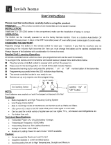
AS250 KEY FOB
3.1 Programming the Transmitter Codes
Note: The AS250 can learn the codes of up to two transmitters, allowing a second transmitter to be used
as a spare or by a second user of the vehicle.
1 DOUBLE-CHECK THE WIRING and reconnect the vehicle battery.
2 Disconnect the back-up battery, if fitted.
3 Reset the AS250 by disconnecting the 9-way connector, wait 10 seconds, and then reconnect.
4 Press the Large button of the transmitter and hold it down until you hear a chirp from the siren, then
release the button.
5 If you have a SECOND transmitter, within 5 seconds, press the large button of the SECOND
transmitter and hold it down until you hear 1 or 2 chirps from the siren, then release the button.
6 Reconnect the back-up battery, if fitted.
Notes:
· After programming the FIRST transmitter code, the AS250 waits for 5 seconds to allow you to
programme the SECOND transmitter. If the AS250 does not receive another transmitter code
within those 5 seconds it automatically exits the programming mode.
· Should you wish to reprogram the transmitter codes, repeat steps 1 to 6 above.
3.2 Shock Sensor Testing and Adjustments
On disarming the alarm, the shock sensor sensitivity can be adjusted to suit your requirements. Proceed
as follows:
1 Arm the alarm by pressing the large button once. The alarm will chirp once to confirm setting.
2 Disarm the alarm by pressing the large button again. The alarm will chirp twice to confirm disarming.
3 Within 10 seconds, press and hold both buttons for 2 seconds. The alarm will chirp once to confirm
that it is now in programming mode.
4 By repeatedly pressing the small button, you can select one of 8 sensitivity levels as indicated by
corresponding tones. The higher the pitch of the tone, the more sensitive the alarm is to shock.
5 Hit the vehicle with your palm to simulate an intrusion.
6 The alarm produces a single chirp sound if the shock sensor is only gently triggered, and a ding-dong
sound if the shock sensor is heavily triggered.
7 Adjust the sensitivity of the sensor, either up or down, by pressing the small button. The ideal setting
is when a gentle bump produces the chirp sound, but a heavy bump, e.g., kicking a tyre, produces the
ding-dong sound.
PDF created with pdfFactory trial version www.pdffactory.com

Sargent Electrical Services Ltd. 2006
AS250 Manual issue 2.doc Page 5 of 8 14/02/06
8 When you are satisfied with the setting, press the large button to exit programming mode. The-alarm
will chirp twice to confirm exit. The alarm will also exit automatically if no buttons are pressed within
10 seconds.
NOTE: DO NOT SET THE SENSITIVITY TOO HIGH AS THIS MAY RESULT IN FALSE ALARMS,
ADJUST THE SENSITIVITY TO THE MINIMUM THAT WILL PROTECT YOUR VEHICLE.
3.3 Siren Tone Selection
A choice of 5 different siren tones and a multi-tone can be selected. Proceed as follows:
1 Arm the alarm by pressing the large button once. The alarm will chirp once to confirm setting.
2 Disarm the alarm by pressing the large button again. The alarm will chirp twice to confirm disarming.
3 Within 10 seconds, press and hold both buttons for 2 seconds. The alarm will chirp once to confirm
that it is now in programming mode.
4 By repeatedly pressing the large button, you can select one of 5 siren tones or the multitone.
5 The last tone produced is the one that will be stored. When you have selected a tone, press the small
button to exit programming mode. The alarm will chirp twice to confirm exit. The alarm will also exit
automatically if no buttons are pressed within 10 seconds.
PDF created with pdfFactory trial version www.pdffactory.com

Sargent Electrical Services Ltd. 2006
AS250 Manual issue 2.doc Page 6 of 8 14/02/06
4 INSTALLATION
PLEASE READ THIS INSTRUCTION MANUAL COMPLETELY BEFORE COMMENCING
INSTALLATION.
CAUTION: DO NOT CONNECT THE SYSTEM TO THE VEHICLE'S POWER SUPPLY UNTIL ALL
WIRING IS COMPLETE AND CHECKED. THIS ALARM CAN ONLY BE USED ON NEGATIVE EARTH
VEHICLES
Disconnect the vehicle battery before commencing any wiring and ensure that wiring is kept away from:
· Moving parts such as cooling fans and control linkages, etc.
· Heat such as from the exhaust manifold and pipes.
· High voltage cables such as spark plug leads.
Secure the wires to the car body or wiring harness at regular intervals, using cable ties or tape. Where
possible, route wires under carpets or trim to give a neat finish and to prevent accidental damage during
cleaning and maintenance activities. To prevent cables being cut by sharp metal edges and causing a
short circuit, ensure that all cables passing through holes in metal panels are protected by rubber
grommets or insulating tape.
TOOLS REQUIRED:
Terminal crimper, Electric drill, Pliers, Philips screwdriver, Voltmeter/Tester, Electrical insulating tape,
Wire cutter, 11mm socket, Wire stripper, 5mm 6mm 7mm 8mm Drill bits.
4.1 Mounting the Alarm System
1 Mount the AS250 in the engine compartment and, if possible, facing the front of the vehicle in order to
obtain best sound results. Do not mount the AS250 'face up' or near heat sources such as the
exhaust manifold. Choose a position, which will not expose the AS250 to excessive moisture, and
allows easy connection of wiring.
2 Using the mounting bracket as a template, mark the position of the fixing holes. Using a 5mm bit, drill
out the holes being careful not to damage any wires, pipes, etc., which may be beneath the panel you
are drilling. Fix the bracket to the vehicle using the self-tapping screws, washers and lock-washers
provided.
3 Mount the AS250 on the bracket and fasten it with the bolts, washers and lock washers provided.
Adjust the unit to the correct angle and tighten the bolts.
4.2 Installing the LED Status Indicator
The LED Status Indicator should be mounted in a highly visible area such as the top of the dashboard,
the steering column cover or the face of the dashboard. There must be at least 16mm clearance behind
the mounting position to accommodate the LED housing. When a suitable position has been found, drill a
8mm hole, taking care not to damage any wiring, etc., beneath the panel you are drilling. Feed the LED
wires through the hole and through the bulkhead into the engine compartment and then to the AS250.
Push-fit the indicator into the mounting hole.
4.3 Installing Bonnet / Boot Pin Switches
Select a suitable position for the Pin Switches. This will probably be in the channel that the bonnet/boot
closes into, as it must be operated by the closure of the bonnet/boot. For the boot, use the gold, fully
adjustable Pin Switch provided. Drill a 7mm hole, taking care not to damage wires and pipes, etc., which
may be beneath the panel you are drilling, and mount the Pin Switch at a depth at which it is operated by
the closed boot. For the bonnet, use the silver, non-adjustable, Pin Switch. Drill a 6mm hole and use an
11 mm socket to self-tap the Pin Switch into position.
Notes:
· The Pin Switch mountings must provide a good electrical connection to the chassis.
· If boot/bonnet lights are fitted to your vehicle and the alarm is used in Current Sensing mode,
the alarm will be set off by the boot/bonnet light switching on. It is therefore not essential, in this
case, that the pin switches are fitted.
PDF created with pdfFactory trial version www.pdffactory.com

Sargent Electrical Services Ltd. 2006
AS250 Manual issue 2.doc Page 7 of 8 14/02/06
4.4 Installing the Back-up Battery
Undo the two retaining screws and remove the battery storage compartment cover. Clip the battery
connector to a PP3 size battery and place it in the battery storage compartment. Connect the 2-pin socket
on the other end of the battery connector to the 2-pin plug on the alarm, noting that the socket only fits
one way round. Position the cover the right way round and secure it with the retaining screws. The battery
must be a quality alkaline long life battery, and should be replaced annually.
4.5 Fitting the Decals
Ensure that the area of window / windscreen that you intend to place the decal on is clean, dry and free
from oil or grease. Simply peel the decal from the backing paper and apply to the inside of the
window/windscreen. The decal alone can be an effective deterrent to a would-be thief.
4.6 Main 9-Way Connector
· RED WIRE: System Power - Constant 12V input. The red wire incorporates a 5A fuse, and is
supplied already connected to the red/white wire (paragraph 7). Locate the cable on the vehicle
that feeds power to the fuse, which protects the interior courtesy light; check that this connection
is capable of supplying at least 10A. Refer to the vehicle-wiring diagram if necessary. Connect
the red wire from the alarm as close as possible to the fuse end of the cable, e.g., on the fuse
holder connector. If the connection is made too close to the battery end of the cable, the Current
Sensing mode may not function properly. (If the Current Sensing mode is not going to be used,
then this connection should be made as close as possible to the battery end of the cable.)
· BLACK WIRE: System Ground. This is the Negative or Ground connection of the AS250. A
good electrical connection to the vehicle body is essential for correct operation. Do not connect it
to any existing Ground wires, instead secure it directly to the vehicle's metalwork with a nut and
bolt (not a screw).
· YELLOW WIRES: Ignition Disable. Locate the wire coming from the ignition key-switch that
supplies power to the ignition coil, if necessary refer to the vehicle handbook. With the vehicle
battery disconnected, cut the cable so as to leave both ends accessible. To check that you have
the correct wire, reconnect the vehicle battery and attempt to start the car. (Handbrake on,
select neutral.) The starter should turn but the engine should not start. Disconnect the vehicle
battery. Connect one of the yellow wires to each end of the cut wire. If these wires are not going
to be used, tape the ends, coil up and secure for possible future use.
· BLACK/WHITE WIRE: LED Status Indicator Connection. Connect this wire to the black wire of
the LED Status Indicator. Connect the red wire of the indicator to a constant 12V supply.
· ORANGE WIRE: Grounded output when armed. This output has a current capacity of 500mA,
and becomes grounded when the Alarm is armed. It is used to control optional accessories such
as automatic central locking, automatic electric window close, starter interrupt, etc., which
operate when the Alarm is armed. See Additional Accessories.
· RED/WHITE WIRE: Indicator Flash Power Input. This wire supplies power to the alarm for the
Indicator Flash Outputs and incorporates a l0A fuse. This wire is already connected to the red
wire (paragraph 1).
· WHITE WIRES: Indicator Flash Outputs. When the Alarm is triggered, these wires each provide
a pulsed 12V, 5A output to flash the vehicle's indicator lights. Connect one wire to the switched
side of the left indicator circuit and the other to the switched side of the right indicator circuit. The
total wattage of bulbs connected to each output must not exceed 60W.
4.7 2-Way Connector
· BLUE WIRE: Ground trigger input. This is the wire that connects to the boot and bonnet Pin
Switches if you have chosen to fit them. Make the connections using the crimp-on bullet
connectors supplied, which push into the base of the Pin Switch. Connect both switches to the
blue wire. This is also the input to which additional Ground Output sensors, such as ultrasonic
detectors, may be connected. See the instructions supplied with the Additional Accessories
described later in this manual. If this wire is not going to be used, tape the end, coil up and
secure for possible future use.
· VIOLET WIRE: Current Sensing Circuit control. Some cars are fitted with electric cooling fans,
which operate for a short period after the ignition is switched off. This could cause the Current
PDF created with pdfFactory trial version www.pdffactory.com

Sargent Electrical Services Ltd. 2006
AS250 Manual issue 2.doc Page 8 of 8 14/02/06
Sensing Circuit to trigger if the Alarm is armed immediately after the ignition is turned off,
resulting in a false alarm. If your vehicle has such a fan, connect the violet wire as follows. If
your vehicle does not have such a fan, tape the end, coil up and secure for possible future use.
Consult the vehicle-wiring diagram if necessary, and locate the switched positive wire to the
vehicle's electric fan relay. The wire required is at 1 2V when the fan is running and at OV when
the fan is not running. Connect the violet wire to the switched positive wire.
Note: To completely disable the Current Sensing facility if it is not required, connect the violet
wire to a point as close as possible to the positive side of the battery. The battery terminal itself
could be used or the other end of the thick cable from the battery to the starter solenoid, where
there may be a more suitable connection point. Instead, protect the vehicle by using Pin
Switches on the doors, boot and bonnet, connected to the blue wire.
4.8 Thin Black Wire: RF Antenna
This is the receiver's RF antenna or aerial and MUST be FULLY extended as straight as possible, angled
AWAY from the chassis or large metal objects. If poor range is encountered, try different antenna
positions. When satisfactory, secure it in position with cable ties or tape. Do not shorten or extend this
wire, as this may adversely affect the operation of the receiver. The antenna MUST NOT be connected to
either Ground or the 12V supply. Tape the end of this wire, if necessary, to prevent short circuits.
5 ADDITIONAL ACCESSORIES AVAILABILITY
5.1 Power lock Door Interface
When added to the system, this interface will automatically operate the vehicle's central locking system (if
fitted), locking the doors when the Alarm is armed and unlocking them when the Alarm is disarmed.
5.2 Spare/Second Key Fob Transmitter
Two button key fob transmitters are available either as replacement or for a second user of the vehicle.
See programming instructions for further details.
5.3 Ultrasonic Movement Detector
CS-18S ultrasonic sensor
Operation voltage range: 8v - 18v DC, Quiescent current: 3ma - 5ma
Detecting range: 0.5m - 3m (adjustable), Output drain: 100ma (max)
Output pulse width: negative pulse about 0.8s-1.2s
Installation notes:
Ultrasonic cells should be placed on the left and right side as high as possible so as to obtain the best
performance. Placing the cells on the same side will reduce the sensitivity.
5.4 Garage Door Module
A receiver module that can use the same key fob transmitter as your alarm and is ideal for garage door
opening and remote light switching.
For prices and availability of accessories, contact Sargent Electrical Services Ltd. on 01482 881655.
PDF created with pdfFactory trial version www.pdffactory.com
/