Roland TD-17KVX Installation guide

Category
Music drums
Type
Installation guide

Roland TD-17KVX is an advanced electronic drum kit that offers a realistic and immersive drumming experience for musicians of all levels. With its wide range of features and capabilities, it provides a versatile and customizable platform for practice, performance, and recording. The TD-17KVX includes a variety of drum pads, cymbals, and a sound module packed with hundreds of high-quality drum and percussion sounds. It also features advanced practice tools, connectivity options, and the ability to expand the kit with additional components.

Roland TD-17KVX is an advanced electronic drum kit that offers a realistic and immersive drumming experience for musicians of all levels. With its wide range of features and capabilities, it provides a versatile and customizable platform for practice, performance, and recording. The TD-17KVX includes a variety of drum pads, cymbals, and a sound module packed with hundreds of high-quality drum and percussion sounds. It also features advanced practice tools, connectivity options, and the ability to expand the kit with additional components.

01
02
MDS-4KVX
Assembly procedure
Parts of the TD-17KVX
03
04
Connection procedure
05
For a left-handed setupAttaching the TD to a dierent location
Setup Guide
© 2018 Roland Corporation
In order to use this device correctly, please carefully read “Using
the Unit Safely” and “Important Notes” (included in each owner’s
manual) before use.
Check the included items
Assemble the stand
* When checking the items
included with the MDS-
4KVX refer to “MDS-4KVX
Owners Manual.
* The tip of the mount is sharp. Handle it with care.
* When setting up or storing the stand, be careful not to pinch the ngers you use to
handle the stand.
Attach the parts
1. Connect the cable to TD as
shown in the illustration.
Insert the connector all the
way, then turn the knobs to
fasten it securely.
2. Labels indicating the pad to
be connected are attached
to the cable. Connect the
cable to the OUTPUT jack of
each pad as shown in the
illustration.
Connect the pads to TD
3. Using the included trigger cable,
connect crash cymbal 2 to the
TD’s CRASH 2 jack.
Connect the AC adaptor
and speakers
Connect the AC adaptor, speakers, or headphones as described in the
owner’s manual of the TD.
* To prevent malfunction and equipment failure, always turn down the volume, and turn
o all the units before making any connections.
The setup described in this guide is for right-handed players. To set up for a left-handed player,
reattach the components as follows.
5 Exchange curved pipes (L) and (R), and straight pipes (L) and (R), left-for-right.
5 Attach holder (C) and the snare pipe to the right side.
5 Exchange the pads and cymbals with their attachment mounts left-for-right.
5 Exchange the TD with its sound module mount left-for-right.
Using the included trigger cable, connect crash cymbal 2 to the TDs
CRASH 2 jack.
9 When you’ve nished making connections, turn on the power as described in the TD-17/17-L Owners Manual, and
verify that you can hear sound.
This completes assembly and connections.
Connect the cables as shown in the illustration.
TD-17KVX
Cymbal mounts
Pad mounts
Pad mounts
Cymbal mount
If the stand wobbles, loosen
this hand knob and adjust
the height.
1.2 m
* For reasons of safety, do not spread the stand
wider than 1.2 meters (47 inches).
CY-12C
PDX-12
PDX-8 PDX-8
PDX-8
CY-13R
CY-12C
KD-10
VH-10
TD-17
Loosen this hand knob, and rotate the
mount holder (L) 90 degrees in the direction
of the arrow.
Diameter: 6.0–7.0 mm
(0.236”–0.276”)
Diameter: 11.7 mm (1/2”)
Max.
Attach the hi-hat (VH-10)
Motion Sensor Unit
CONTROL OUT jack on the
farther side
Clutch screw
Hi-Hat
“Roland” logo on the
farther side
Insulating Plate
Sponge side up
Compatible hi-hat stand
Attach the TD
1. Align the protrusions of the
sound module mount with the
rails of the TD, and slide it in until
you hear it click.
2. Loosen the hand knob of the
mount holder, and insert the
sound module mount.
3. Adjust the angle of the TD, and
then tighten the hand knob.
Tighten the wing nut to
obtain an appropriate
amount of sway.
Attach the crash cymbal (CY-12C) and ride cymbal (CY-13R)
Wing nut
Felt washer
Attach the snare (PDX-12) and toms (PDX-8)
Loosen
Tighten
Rod
Loosen
Tighten
Rod
Attach the kick pedal (KD-10)
Install the kick pedal securely.
Adjust the height of the rod so that the highest point of the cymbal is
less than 1.2 meters.
1.2 m
OK Not OK
Attach the cymbal so that its center does not extend toward the back
beyond the pipes of the stand (the pipes at the back of the stand).
Adjusting the position of the cymbal
Knob
As seen from the back
CR1
T2 T1
T3
KIK
HH
SNR
RD
RDB
TD-17
Symbal side
TD-17 side
* Fasten the cables so that they will
not obstruct your playing; use cable
clips and cable ties.
Make sure to wrap the cable ties
around the pipes.
BOW/EDGE
OUTPUT jack
BELL
OUTPUT jack
RD plug
RDB plug
You can change the location at which the TD is attached,
so that the hi-hat stand is on the outside as shown in the
illustration.
1. Position the sound module mount as shown in the illustration below,
and attach it to the TD.
2. Of the mount holders of curved pipe (L), insert the sound module
mount into the mount holder to which the cymbal mount is not
attached.
“Roland” logo on the farther side
* Insert the plug rmly,
making sure it’s all the
way in.
TRIGGER OUT
Jack
CONTROL OUT
Jack
HH plug
HHC plug
HHC
Connection cable
Trigger cable
Crash
Cymbal 2
8 Kick pad (KD-10) 8 V-Hi-hat (VH-10)
8 V-Cymbal for crash
(CY-12C x 2)
8 V-Pad for snare (PDX-12)
8 V-Pad for tom
(PDX-8 x 3)
8 V-Cymbal for ride
(CY-13R)
8 Drum sound module (TD)
(TD-17)
8 Connection cable
(special for TD)
8 AC adaptor
8 Setup Guide (this document)
8 Owners manual set
8 Trigger cable
As soon as you open the package, check to see that all items are included. If anything is missing, please contact your dealer.
* This package does not include a kick pedal, and a hi-hat stand. Use with a commercially available kick pedal, hi-hat stand, and snare stand.
CY-12C
PDX-12
PDX-8
PDX-8
CY-13R
CY-12C
KD-10
VH-10
TD-17
PDX-8
(T1)
(T2)
(T3)
(SNR)
(KIK)
(HH)
(CR1)
(RD) (RDB)
Remove the caps, remove holder (C) and the snare pipe,
and reattach them to the right side.
Connection cable
Trigger cable
CR1
T2T1
T3
KIK
RD
RDB
TD-17
HHC
SNR
HH
Crash
Cymbal 2
As seen from the back
Assemble the stand using the procedure described in “MDS-4KVX Owner’s Manual.
Attach the stopper so that
the bolt is on the right-hand
side, from the performer’s
perspective.
Tighten the bolt with a drum key.
Stopper
(Be sure to orient it correctly)
Adjust the location at which
the KD-10 is installed so that
it’s at a comfortable position
for playing.
After exchanging the curved pipes, attach
the holders so that the marks on the pipes
are visible through the gaps of the holders.
Mark
Straight pipe R
(short)
Curved pipe R
(including the pad mount)
Straight pipe L (long)
Curved pipe L
Detailed explanation of each part
9 Adjust the VH-10
9 KD-10 (Kick)
9 PDX-12 (Snare)
9 CY-12C (Crash) 9 CY-13R (Ride)9 PDX-8 (Tom)
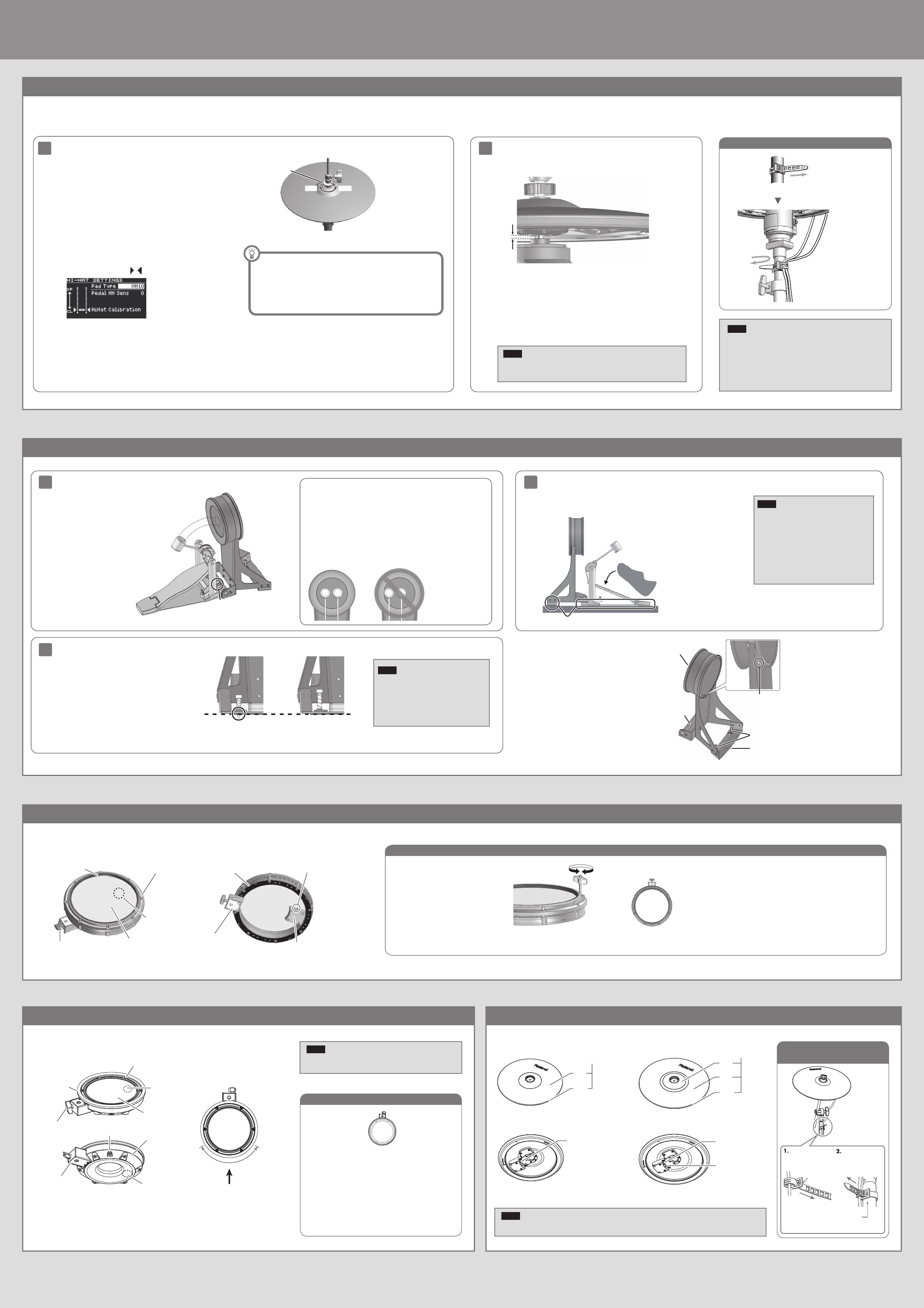
Fixing the cables
(CY-13R/CY-12C)
Secure the cable
in place with the
cable tie
Leave some slack in
the cables
Be sure to make this
small plastic hook
visible from you.
Wind a cable tie
around the pipe and
tighten it in order to
not to slip.
Wind a cable tie around
a cable.
Insert the small plastic hook to a hole
to secure the cable to the cymbal arm.
Beater
Install the kick pedal
securely.
Position the beater so that it strikes the
center of the head, then secure the kick
pedal and KD-10 rmly in place.
* A variety of commercially available
beaters can be used, including felt,
plastic, or wood types. However if a felt
beater is used, the felt may leave marks
on the striking surface.
01
Correct positioning Incorrect positioning
02
Check to be sure they’re making contact with the oor
03
When using on the V-Drums mat, noise
eater, or carpet
When using on the oor
Head
OUTPUT jack
Anchor bolts
Slip-prevention tape
Mounting plate for
the kick pedal
Adjusting the head tension
OUTPUT jack
Tuning bolts
Knob bolt
Hoop rubber
Head sensor
Rim sensor
Head
Holder
Shell
Adjusting the head tension
When the unit is shipped from the factory,
this is adjusted fairly loosely.
Before use, adjust the head to a fairly high
tension.
18
72
36
54
Tighten
Loosen
1. Adjust each tuning bolt a little at a time, moving in order from one side to
the opposite side as shown in the illustration.
2. Fine-tune the adjustment while continuing to check the pad feel and
response.
* Do not rmly tighten a single tuning bolt by itself. Doing so will make it
impossible to tension the head evenly, and will cause malfunctions.
01
OPEN CLOSE
Oset
Adjustment
Screw
02
When using the VH-10, be sure to adjust the oset on the TD after connection.
This adjustment is required in order to correctly detect open, close, and pedal operations.
Wind the
cable tie once
Tighten it not to slip
Leave some slack in the
cables
Turn back to x the cables
Fixing the cables
1. Make adjustments so that the cosmetic part in the lower middle of the hi-hat is
3 mm away from the center tip of the sensor, and then tighten the clutch screw.
3mm3mm
* The spacing can be adjusted to the distance that you nd comfortable for
playing, but if it is too narrow or too wide, malfunctions may occur, and you
might not be able to play as expected.
3 mm is the spacing at which you’ll be able to play the VH-10 with the most
natural feel.
2. Use the hi-hat stand to adjust the tension of the pedal spring.
* Depending on the stand, it might not be possible to make adjustments.
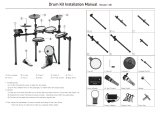
1. After making the hi-hat settings, release your foot from the pedal, and
while keeping your foot o the pedal, turn on the power of the TD.
2. Loosen the clutch screw and let the hi-hat rest naturally on the motion
sensor unit.
3. Press the [SETUP] button.
4. Use the dial to select the “Hi-Hat Settings, and press the [ENTER]
button.
5. Turn the dial to set the Pad Type to VH10.
6. While watching the meter that’s shown in the right of the screen,
make adjustments by turning the VH oset adjustment screw of the
VH-10.
Adjust the oset so that the
appear in the meter.
7. Press the [DRUM KIT] button to return the KIT screen.
Adjust the oset.
NOTE
The hi-hat has a correct orientation. You’ll obtain the optimal sensitivity if the
“Roland” logo is toward the back as seen from the performer.
Adjust the hi-hat.
If you nd the closed hi-hat sound dicult to play, turn the VH oset
adjustment screw toward “CLOSE.
If you nd the open hi-hat sound dicult to play, turn it toward “OPEN.
* If the sound is interrupted when you play a strong strike, adjust the VH
oset adjustment screw toward “OPEN.
NOTE
* Continuous playing may cause dis-coloration of the pad, but this
will not aect the Pad’s function.
* If the hi-hat clutch has been detached from the hi-hat, refer to “If
the Clutch Was Apart from the Hi-Hat in the owners manual.
NOTE
* Attach the KD-10 and the kick pedal securely.
* Take care not to pinch your ngers.
* Depending on how you’re using the unit,
the bolts that attach the pedal to the plate
could become loose, causing the pedal to
rattle during performance. In such cases, use
commercially available tools to tighten the
bolts.
Adjusting the Anchor Bolts.
If you’re using this unit on a V-Drums mat, on a noise eater
(NE-10), or on carpet, extending the anchor bolts will
secure the unit in place.
However, if that’s not enough to keep the KD-10 in a xed
position, you can adjust things so that the tips of the
anchor bolts protrude through the base. That should keep
it in place and make it easier for you to play.
When Using a Twin Pedal
Position the two beaters equally apart from the center of the pad as shown in
the gure at left. If one of the beater is further away from the center than the
other, the sound from the further beater will be lower in volume, or will not
sound as desired.
If you’re using twin pedals, the sensitivity will be lower than when a single
pedal is used. Raise the sensitivity on the sound module.
For details, refer to the TD’s owners manual.
NOTE
* When used on ooring, the anchor bolts
may damage the oor. Adjust the anchor
bolts correctly.
* The tips of the anchor bolts are sharp.
Handle with care.
Component names
Attach the kick pedal.
Step on the kick pedal and make sure that it’s properly attached
and in a stable position.
Check to make sure that the base of the KD-10 and the kick pedal both make contact
with the oor.
Component names
CY-12C component names CY-13R component names
BOW/EDGE
OUTPUT jack
Pad face
Bow
Edge
Bell
BELL
OUTPUT jack
Pad face
Bow
Edge
BOW/EDGE
OUTPUT jack
NOTE
Continuous playing may cause dis-coloration of the pad, but this will not aect the Pad’s function.
Component names
Suitable position
for rim shots
Player
1. Adjust each tuning bolt a little at a time, moving in order from
one side to the opposite side as shown in the illustration.
The appropriate amount of tension is one that will provide
approximately the same striking response as on an acoustic
drum.
2. Use the drum key to adjust the tension as needed.
Knob bolt
Head
Tuning bolts
OUTPUT jack
Hoop rubber
Head sensor
Shell
Rim sensor
Holder
NOTE
Be sure to adjust the head tension of the pad before use.
4 3
2 5
6 1
1 / 1

Roland TD-17KVX Installation guide

Category
Music drums
Type
Installation guide

Roland TD-17KVX is an advanced electronic drum kit that offers a realistic and immersive drumming experience for musicians of all levels. With its wide range of features and capabilities, it provides a versatile and customizable platform for practice, performance, and recording. The TD-17KVX includes a variety of drum pads, cymbals, and a sound module packed with hundreds of high-quality drum and percussion sounds. It also features advanced practice tools, connectivity options, and the ability to expand the kit with additional components.

Ask a question and I''ll find the answer in the document

Finding information in a document is now easier with AI

Ask the document