Page is loading ...

MODEL G0805
SUPER HD ANGLE NOTCHER,
9-GAUGE
OWNER'S MANUAL
(For models manufactured since 01/16)
COPYRIGHT © NOVEMBER, 2016 BY GRIZZLY INDUSTRIAL, INC.,
WARNING: NO PORTION OF THIS MANUAL MAY BE REPRODUCED IN ANY SHAPE
OR FORM WITHOUT THE WRITTEN APPROVAL OF GRIZZLY INDUSTRIAL, INC.
#JH18067 PRINTED IN TAIWAN
V1.11.16

This manual provides critical safety instructions on the proper setup,
operation, maintenance, and service of this machine/tool. Save this
document, refer to it often, and use it to instruct other operators.
Failure to read, understand and follow the instructions in this manual
may result in fire or serious personal injury—including amputation,
electrocution, or death.
The owner of this machine/tool is solely responsible for its safe use.
This responsibility includes but is not limited to proper installation in
a safe environment, personnel training and usage authorization,
proper inspection and maintenance, manual availability and compre-
hension, application of safety devices, cutting/sanding/grinding tool
integrity, and the usage of personal protective equipment.
The manufacturer will not be held liable for injury or property damage
from negligence, improper training, machine modifications or misuse.
Some dust created by power sanding, sawing, grinding, drilling, and
other construction activities contains chemicals known to the State
of California to cause cancer, birth defects or other reproductive
harm. Some examples of these chemicals are:
• Lead from lead-based paints.
• Crystalline silica from bricks, cement and other masonry products.
• Arsenic and chromium from chemically-treated lumber.
Your risk from these exposures varies, depending on how often you
do this type of work. To reduce your exposure to these chemicals:
Work in a well ventilated area, and work with approved safety equip-
ment, such as those dust masks that are specially designed to filter
out microscopic particles.

INTRODUCTION ............................................................................................................................... 2
Contact Info ................................................................................................................................ 2
Manual Accuracy ........................................................................................................................ 2
Identification ............................................................................................................................... 3
Controls & Components ............................................................................................................. 4
Machine Data Sheet ................................................................................................................... 6
SECTION 1: SAFETY ....................................................................................................................... 8
Safety Instructions for Machinery ............................................................................................... 8
Additional Safety Instructions for Notchers .............................................................................. 10
SECTION 2: POWER SUPPLY ...................................................................................................... 11
440V Conversion ...................................................................................................................... 13
SECTION 3: SETUP ....................................................................................................................... 15
Needed for Setup ..................................................................................................................... 15
Unpacking ................................................................................................................................ 15
Inventory ................................................................................................................................... 16
Cleanup .................................................................................................................................... 16
Site Considerations .................................................................................................................. 17
Lifting & Placing ....................................................................................................................... 18
Test Run ................................................................................................................................... 18
SECTION 4: OPERATIONS ........................................................................................................... 20
Operation Overview.................................................................................................................. 20
Adjusting Fences ...................................................................................................................... 21
Aligning Blades......................................................................................................................... 22
Setting Stroke Depth ................................................................................................................ 23
Cutting Notches ........................................................................................................................ 24
SECTION 5: ACCESSORIES ......................................................................................................... 25
SECTION 6: MAINTENANCE......................................................................................................... 27
Schedule .................................................................................................................................. 27
Cleaning & Protecting .............................................................................................................. 27
Lubrication ................................................................................................................................ 27
SECTION 7: SERVICE ................................................................................................................... 29
Troubleshooting ........................................................................................................................ 29
SECTION 8: WIRING ...................................................................................................................... 31
Wiring Safety Instructions ........................................................................................................ 31
Electrical Components ............................................................................................................. 32
220V Wiring Diagram ............................................................................................................... 33
440V Wiring Diagram ............................................................................................................... 34
Hydraulic & Motor Wiring Diagram ........................................................................................... 35
SECTION 9: PARTS ....................................................................................................................... 36
Main Parts Diagram ................................................................................................................. 36
Labels & Cosmetics ................................................................................................................. 38
WARRANTY AND RETURNS ........................................................................................................ 41
Table of Contents

-2-
Model G0805 (Mfd. Since 1/16)
We stand behind our machines! If you have ques-
tions or need help, contact us with the information
below. Before contacting, make sure you get the
serial number
and manufacture date from the
machine ID label. This will help us help you faster.
Grizzly Technical Support
1815 W. Battlefield
Springfield, MO 65807
Phone: (570) 546-9663
Email: [email protected]
We want your feedback on this manual. What did
you like about it? Where could it be improved?
Please take a few minutes to give us feedback.
Grizzly Documentation Manager
P.O. Box 2069
Bellingham, WA 98227-2069
Email: [email protected]
Contact Info
We are proud to provide a high-quality owner’s
manual with your new machine!
We
made every effort to be exact with the
instruc-
tions, specifications, drawings, and photographs
in this manual. Sometimes we make mistakes, but
our policy of continuous improvement also means
that
sometimes the machine
you receive is
slightly different than shown in the manual
.
If you find this to be the case, and the difference
between the manual and machine leaves you
confused or unsure about something
,
check our
website for an updated version. W
e post
current
manuals and
manual updates for free
on our web-
site at
www.grizzly.com.
Alternatively, you can call our Technical Support
for help. Before calling, make sure you write down
the
Manufacture Date and Serial Number
from
the machine ID label (see below). This information
is required for us to provide proper tech support,
and it helps us determine if updated documenta-
tion is available for your machine.
Manufacture Date
Serial Number
Manual Accuracy
INTRODUCTION

Model G0805 (Mfd. Since 1/16)
-3-
Blade
Guard
Work Table
Foot Pedal
Identification
Become familiar with the names and locations of the controls and features shown below to better understand
the instructions in this manual.
Emergency Stop
Button
Waste
Chute
Adjustable Fence
Depth-of-Cut
Gauge
Shear Blade
Adjustable Fence
Control
Panel

-4-
Model G0805 (Mfd. Since 1/16)
Controls &
Components
Figure 2. Base controls and components.
Hydraulic Pressure Gauge: Shows amount of
hydraulic pressure applied to cut (see Lubrication
on Page 27).
Hydraulic Ram: Actuates shear blades when foot
pedal is pressed.
Hydraulic Fluid Regulator: Controls hydraulic
fluid pressure available to ram.
Hydraulic Tank: Holds 23.25 quarts of ISO 32
hydraulic fluid. Features a clear gauge to check
fluid level.
Hydraulic Components
Refer to Figures 1–4 and the following descrip-
tions to become familiar with the basic controls
and components of this machine. Understanding
these items and how they work will help you
understand the rest of the manual and stay safe
when operating this machine.
To reduce your risk of
serious injury, read this
entire manual BEFORE
using machine.
Work Area Controls & Components
Adjustable Fences: Allow quick cut and angle
alignment of workpiece for repeat notching opera-
tions.
Blade Guard: Reduces risk of finger amputation
during operation of notcher. Do not remove blade
guard during cutting operation or while connected
to power.
Notch Size Scale: Provides reference for adjust-
able fence when adjusting notch size.
Figure 1. Work area components.
Shear
Blades
Blade
Guard
Notch Size
Scale
Hydraulic
Tank
Hydraulic Ram
Hydraulic
Pressure
Gauge
Hydraulic
Fluid Regulator
Adjustable Fence
(1 of 2)

Model G0805 (Mfd. Since 1/16)
-5-
Emergency Stop Button: Stops all cutting ac-
tion. Twist clockwise and pull outward to reset.
Foot Pedal: Controls cutting action of shear
blades. Pedestal connects to machine via four-
foot-long flexible control line.
Figure 3. Foot pedal control.
Foot
Pedal
Control Pedestal
Emergency
Stop Button
Figure 4. Electrical controls on control panel.
Control Panel
UP/DOWN Switch: Controls cutting action of
shear blades in MANUAL mode. Turning switch
will raise or lower blade in one direction only.
MANUAL/AUTO Switch: Switches notcher blade
movement from foot pedal-controlled (AUTO) to
UP/DOWN switch-controlled (MANUAL).
ON/OFF Button: Turns machine ON ("I" button)
or OFF ("O" button). Indicator light illuminates
when machine is turned ON.
ON/OFF
Button
MANUAL/
AUTO
Switch
UP/DOWN
Switch

-6-
Model G0805 (Mfd. Since 1/16)
Page 1 of 2 Model G0805
MODEL G0805
SUPER HEAVY-DUTY ANGLE NOTCHER, 9-GAUGE
Product Dimensions:
Weight ........................................................................................................................................................................... 827 lbs.
Width (side-to-side) x Depth (front-to-back) x Height .......................................................................................40 x 26 x 40 in.
Footprint (Length x Width) ............................................................................................................................ 27-1/2 x 20-1/2 in.
Shipping Dimensions:
Type ........................................................................................................................................................................ Wood Crate
Weight ............................................................................................................................................................................ 904 lbs.
Length x Width x Height .....................................................................................................................................37 x 29 x 44 in.
Must Ship Upright .................................................................................................................................................................Yes
Electrical:
Required Requirement .............................................................................................................. 220V or 440V, 3-Phase, 60 Hz
Prewired Voltage ................................................................................................................................................................ 220V
Full-Load Current Rating .................................................................................................................8.6A at 220V, 4.3A at 440V
Minimum Circuit Size ........................................................................................................................15A at 220V, 15A at 440V
Connection Type .................................................................................... Cord & Plug at 220V, Permanent (Hardwire) at 440V
Power Cord Included ............................................................................................................................................................Yes
Power Cord Length ...............................................................................................................................................................6 ft.
Power Cord Gauge ....................................................................................................................................................... 14 AWG
Plug Included ......................................................................................................................................................................... No
Recommended Plug Type ..................................................................................................................................15-15 for 220V
Switch Type ..................................................................................................................................ON/OFF Push Button Switch
Motor:
Main
Type ..........................................................................................................................................................TEFC Induction
Horsepower ...............................................................................................................................................................3 HP
Phase .................................................................................................................................................................. 3-Phase
Amps .................................................................................................................................................................8.6A/4.3A
Speed ...............................................................................................................................................................1720 RPM
Power Transfer ...............................................................................................................................................Direct Drive
Bearings .........................................................................................................................Shielded & Permanently Sealed

Model G0805 (Mfd. Since 1/16)
-7-
Model G0805Page 2 of 2
Main Specifications:
Operation Information
Maximum Thickness Mild Steel ...........................................................................................................................9 Gauge
Maximum Hydraulic Power ...................................................................................................................................12 Tons
Maximum Notch Size .............................................................................................................................. 7-7/8 x 7-7/8 in.
Notch Angle ...........................................................................................................................................................90 deg.
Strokes Per Minute ........................................................................................................................................................50
Table Size (Length x Width) ................................................................................................................ 23-1/2 x 27-1/2 in.
Table Thickness ...................................................................................................................................................1-7/8 in.
Floor-to-Table Height .........................................................................................................................................35-1/2 in.
Oil Tank Capacity .....................................................................................................................................................5 gal.
Construction
Base ..........................................................................................................................................................................Steel
Table ................................................................................................................................................................... Cast Iron
Headstock/Ram .................................................................................................................................................. Cast Iron
Guard ...................................................................................................................................................................... Acrylic
Shear Blades ...............................................................................................................Precision-Ground Hardened Steel
Paint/Finish ............................................................................................................................................................Enamel
Other Specifications:
Country of Origin ............................................................................................................................................................. Taiwan
Warranty ........................................................................................................................................................................... 1 Year
Approximate Assembly & Setup Time ...................................................................................................................... 30 Minutes
Serial Number Location ................................................................................................................................................ ID Label
ISO 9001 Factory ................................................................................................................................................................... No
CSA Certified ......................................................................................................................................................................... No
Features:
9-Gauge Mild Steel Cutting Capacity
Emergency Stop Button on Foot-Control Pedestal
12-Ton Force Capacity
7
7
⁄8" x 7
7
⁄8" Max Notch Dimension
50 Strokes Per Minute
Foot-Controlled, Hydraulic-Powered Cutting Operation
Large 23
1
⁄2" x 27
1
⁄2" Cast Iron Table Features Angle Guides and Inch/Metric Scales

-8-
Model G0805 (Mfd. Since 1/16)
ELECTRICAL EQUIPMENT INJURY RISKS. You
can be shocked, burned, or killed by touching live
electrical components or improperly grounded
machinery. To reduce this risk, only allow qualified
service personnel to do electrical installation or
repair work, and always disconnect power before
accessing or exposing electrical equipment.
DISCONNECT POWER FIRST.
Always discon-
nect machine from power supply BEFORE making
adjustments, changing tooling, or servicing machine.
This prevents an injury risk from unintended startup
or contact with live electrical components.
EYE PROTECTION. Always wear ANSI-approved
safety glasses or a face shield when operating or
observing machinery to reduce the risk of eye
injury or blindness from flying particles. Everyday
eyeglasses are NOT approved safety glasses.
OWNER’S MANUAL. Read and understand this
owner’s manual BEFORE using machine.
TRAINED OPERATORS ONLY. Untrained oper-
ators have a higher risk of being hurt or killed.
Only allow trained/supervised people to use this
machine. When machine is not being used, dis-
connect power, remove switch keys, or lock-out
machine to prevent unauthorized use—especially
around children. Make workshop kid proof!
DANGEROUS ENVIRONMENTS. Do not use
machinery in areas that are wet, cluttered, or have
poor lighting. Operating machinery in these areas
greatly increases the risk of accidents and injury.
MENTAL ALERTNESS REQUIRED. Full mental
alertness is required for safe operation of machin-
ery. Never operate under the influence of drugs or
alcohol, when tired, or when distracted.
For Your Own Safety, Read Instruction
Manual Before Operating This Machine
The purpose of safety symbols is to attract your attention to possible hazardous conditions.
This manual uses a series of symbols and signal words intended to convey the level of impor-
tance of the safety messages. The progression of symbols is described below. Remember that
safety messages by themselves do not eliminate danger and are not a substitute for proper
accident prevention measures. Always use common sense and good judgment.
Indicates a potentially hazardous situation which, if not avoided,
MAY result in minor or moderate injury. It may also be used to alert
against unsafe practices.
Indicates a potentially hazardous situation which, if not avoided,
COULD result in death or serious injury.
Indicates an imminently hazardous situation which, if not avoided,
WILL result in death or serious injury.
This symbol is used to alert the user to useful information about
proper operation of the machine.
NOTICE
Safety Instructions for Machinery
SECTION 1: SAFETY

Model G0805 (Mfd. Since 1/16)
-9-
WEARING PROPER APPAREL. Do not wear
clothing, apparel or jewelry that can become
entangled in moving parts. Always tie back or
cover long hair. Wear non-slip footwear to reduce
risk of slipping and losing control or accidentally
contacting cutting tool or moving parts.
HAZARDOUS DUST. Dust created by machinery
operations may cause cancer, birth defects, or
long-term respiratory damage. Be aware of dust
hazards associated with each workpiece mate-
rial. Always wear a NIOSH-approved respirator to
reduce your risk.
HEARING PROTECTION. Always wear hear-
ing protection when operating or observing loud
machinery. Extended exposure to this noise
without hearing protection can cause permanent
hearing loss.
REMOVE ADJUSTING TOOLS. Tools left on
machinery can become dangerous projectiles
upon startup. Never leave chuck keys, wrenches,
or any other tools on machine. Always verify
removal before starting!
USE CORRECT TOOL FOR THE JOB. Only use
this tool for its intended purpose—do not force
it or an attachment to do a job for which it was
not designed. Never make unapproved modifica-
tions—modifying tool or using it differently than
intended may result in malfunction or mechanical
failure that can lead to personal injury or death!
AWKWARD POSITIONS. Keep proper footing
and balance at all times when operating machine.
Do not overreach! Avoid awkward hand positions
that make workpiece control difficult or increase
the risk of accidental injury.
CHILDREN & BYSTANDERS. Keep children and
bystanders at a safe distance from the work area.
Stop using machine if they become a distraction.
GUARDS & COVERS. Guards and covers reduce
accidental contact with moving parts or flying
debris. Make sure they are properly installed,
undamaged, and working correctly BEFORE
operating machine.
FORCING MACHINERY. Do not force machine.
It will do the job safer and better at the rate for
which it was designed.
NEVER STAND ON MACHINE. Serious injury
may occur if machine is tipped or if the cutting
tool is unintentionally contacted.
STABLE MACHINE. Unexpected movement dur-
ing operation greatly increases risk of injury or
loss of control. Before starting, verify machine is
stable and mobile base (if used) is locked.
USE RECOMMENDED ACCESSORIES. Consult
this owner’s manual or the manufacturer for rec-
ommended accessories. Using improper acces-
sories will increase the risk of serious injury.
UNATTENDED OPERATION. To reduce the
risk of accidental injury, turn machine OFF and
ensure all moving parts completely stop before
walking away. Never leave machine running
while unattended.
MAINTAIN WITH CARE. Follow all maintenance
instructions and lubrication schedules to keep
machine in good working condition. A machine
that is improperly maintained could malfunction,
leading to serious personal injury or death.
DAMAGED PARTS. Regularly inspect machine
for damaged, loose, or mis-adjusted parts—or
any condition that could affect safe operation.
Immediately repair/replace BEFORE operating
machine. For your own safety, DO NOT operate
machine with damaged parts!
MAINTAIN POWER CORDS. When disconnect-
ing cord-connected machines from power, grab
and pull the plug—NOT the cord. Pulling the cord
may damage the wires inside. Do not handle
cord/plug with wet hands. Avoid cord damage by
keeping it away from heated surfaces, high traffic
areas, harsh chemicals, and wet/damp locations.
EXPERIENCING DIFFICULTIES. If at any time
you experience difficulties performing the intend-
ed operation, stop using the machine! Contact our
Technical Support at (570) 546-9663.

-10-
Model G0805 (Mfd. Since 1/16)
Additional Safety Instructions for Notchers
No list of safety guidelines can be complete.
Every shop environment is different. Always
consider safety first, as it applies to your
individual working conditions. Use this and
other machinery with caution and respect.
Failure to do so could result in serious per-
sonal injury, damage to equipment, or poor
work results.
Like all machinery there is potential danger
when operating this machine. Accidents are
frequently caused by lack of familiarity or
failure to pay attention. Use this machine
with respect and caution to lessen the pos-
sibility of operator injury. If normal safety
precautions are overlooked or ignored, seri-
ous personal injury may occur.
Fingers, hands, etc. can be amputated or severely pinched by notching blades. Workpieces
or cut-offs can be ejected by notcher at high speeds and strike operator or bystanders. To
minimize risk of injury, anyone operating this machine MUST completely heed hazards and
warnings below.
GUARDS. Keep all guards in place, properly
positioned, and in working order. If bladeguard
is removed or not properly positioned, fingers
may accidentally be cut or amputated by blades.
Always position guard just high enough to allow
workpiece to enter but not fingers.
CHECK MACHINE. Carefully check components
of notcher prior to use for wear that could affect
operation. Check blade alignment, notching depth
and gib play, and ensure guard is properly
installed.
HANDS AND FINGERS. Always keep hands and
fingers away from blade during notching opera-
tions to avoid contact with blades. If hands or
fingers enter blade path during use, serious injury
may occur.
EXPERIENCING DIFFICULTIES. If at any time
you are experiencing difficulties performing
the intended operation, stop using the notcher!
Contact Tech Support at (570) 546-9663.
CAPACIT Y. Never exceed the rated capacity of
this notcher. Doing so could result in machine fail-
ure and bodily injury as a result of flying debris or
sudden unexpected movement or breakage.
OPERATOR POSITION. Avoid awkward body and
hand positions where a sudden slip could cause
your hand or body to fall into work area or a sharp
edge of workpiece.
MAINTENANCE/SERVICE. Always disconnect
air from machine and wait for all moving parts to
come to a complete stop before preforming any
inspections, adjustments, and maintenance.
SHEAR BLADE ADJUSTMENT. When replac-
ing blades, disconnect machine from power, and
wear gloves to protect hands and safety glasses
to protect eyes.
METAL EDGES. The sharp edges of sheet metal
can quickly cut your fingers or hands. Always
wear heavy leather gloves when handling sheet
metal. Always chamfer and deburr sharp metal
edges before inserting them into notcher.

Model G0805 (Mfd. Since 1/16)
-11-
SECTION 2: POWER SUPPLY
Availability
Before installing the machine, consider the avail-
ability and proximity of the required power supply
circuit. If an existing circuit does not meet the
requirements for this machine, a new circuit must
be installed. To minimize the risk of electrocution,
fire, or equipment damage, installation work and
electrical wiring must be done by an electrician or
qualified service personnel in accordance with all
applicable codes and standards.
Electrocution, fire, shock,
or equipment damage
may occur if machine is
not properly grounded
and connected to power
supply.
Full-Load Current Rating
The full-load current rating is the amperage a
machine draws at 100% of the rated output power.
On machines with multiple motors, this is the
amperage drawn by the largest motor or sum of all
motors and electrical devices that might operate
at one time during normal operations.
Full-Load Current Rating at 220V .... 8.6 Amps
Full-Load Current Rating at 440V .... 4.3 Amps
The full-load current is not the maximum amount
of amps that the machine will draw. If the machine
is overloaded, it will draw additional amps beyond
the full-load rating.
If the machine is overloaded for a sufficient length
of time, damage, overheating, or fire may result—
especially if connected to an undersized circuit.
To reduce the risk of these hazards, avoid over-
loading the machine during operation and make
sure it is connected to a power supply circuit that
meets the specified circuit requirements.
Circuit Requirements for 220V
This machine is prewired to operate on a power
supply circuit that has a verified ground and meets
the following requirements:
Nominal Voltage ................... 220V, 230V, 240V
Cycle ..........................................................60 Hz
Phase .................................................... 3-Phase
Power Supply Circuit ......................... 15 Amps
Plug/Receptacle ............................NEMA 15-15
Circuit Requirements for 440V
This machine can be converted to operate on a
power supply circuit that has a verified ground
and meets the requirements listed below. (Refer
to Voltage Conversion instructions for details.)
Nominal Voltage ............................. 440V, 480V
Cycle ..........................................................60 Hz
Phase .................................................... 3-Phase
Power Supply Circuit ......................... 15 Amps
Connection ........Hardwired w/Locking Switch
Note: Circuit requirements in this manual apply to
a dedicated circuit—where only one machine will
be running on the circuit at a time. If machine will
be connected to a shared circuit where multiple
machines may be running at the same time, con-
sult an electrician or qualified service personnel to
ensure circuit is properly sized for safe operation.
For your own safety and protection of
property, consult an electrician if you are
unsure about wiring practices or electrical
codes in your area.
A power supply circuit includes all electrical
equipment between the breaker box or fuse panel
in the building and the machine. The power sup-
ply circuit used for this machine must be sized to
safely handle the full-load current drawn from the
machine for an extended period of time. (If this
machine is connected to a circuit protected by
fuses, use a time delay fuse marked D.)
Circuit Information

-12-
Model G0805 (Mfd. Since 1/16)
Extension Cords
We do not recommend using an extension cord
with this machine.
If you must use an extension
cord, only use it if absolutely necessary and only
on a temporary basis.
Extension cords cause voltage drop, which can
damage electrical components and shorten motor
life. Voltage drop increases as the extension cord
size gets longer and the gauge size gets smaller
(higher gauge numbers indicate smaller sizes).
Any extension cord used with this machine must
be in good condition and contain a ground wire
and matching plug/receptacle. Additionally, it must
meet the following size requirements:
Minimum Gauge Size ...........................14 AWG
Maximum Length (Shorter is Better).......50 ft.
Improper connection of the equipment-grounding
wire can result in a risk of electric shock. The
wire with green insulation (with or without yellow
stripes) is the equipment-grounding wire. If repair
or replacement of the power cord or plug is nec-
essary, do not connect the equipment-grounding
wire to a live (current carrying) terminal.
Check with a qualified electrician or service per-
sonnel if you do not understand these grounding
requirements, or if you are in doubt about whether
the tool is properly grounded. If you ever notice
that a cord or plug is damaged or worn, discon-
nect it from power, and immediately replace it with
a new one.
Serious injury could occur if you connect
machine to power before completing setup
process. DO NOT connect to power until
instructed later in this manual.
220V Connection Type
The power cord and plug specified under “Circuit
Requirements for 220V”
on the previous page
has an equipment-grounding wire and a ground-
ing prong. The plug must only be inserted into
a matching receptacle (outlet) that is properly
installed and grounded in accordance with all
local codes and ordinances (see figure below).
No adapter should be used with plug. If
plug does not fit available receptacle, or if
machine must be reconnected for use on a
different type of circuit, reconnection must
be performed by an electrician or qualified
service personnel, and it must comply with
all local codes and ordinances.
Figure 5. Typical 15-15 plug and receptacle.
Current
Carrying
Prongs
15-15 PLUG
GROUNDED
15-15 RECEPTACLE
Grounding Prong
Serious injury could occur if you connect
machine to power before completing setup
process. DO NOT connect to power until
instructed later in this manual.

Model G0805 (Mfd. Since 1/16)
-13-
Extension Cords
Since this machine must be permanently con-
nected to the power supply, an extension cord
cannot be used.
Figure 6. Typical setup of a permanently
connected machine.
Power
Source
Locking
Disconnect Switch
Machine
Ground
Ground
ConduitConduit
Connection Type
A permanently connected (hardwired) power sup-
ply is typically installed with wires running through
mounted and secured conduit. A disconnecting
means, such as a locking switch (see following
figure), must be provided to allow the machine
to be disconnected (isolated) from the power
supply when required. This installation must be
performed by an electrician in accordance with all
applicable electrical codes and ordinances.
Serious injury could occur if you connect
machine to power before completing setup
process. DO NOT connect to power until
instructed later in this manual.
Grounding Instructions
In the event of a malfunction or breakdown,
grounding provides a path of least resistance
for electrical current to reduce the risk of electric
shock. A permanently connected machine must
be connected to a grounded metal permanent wir-
ing system; or to a system having an equipment-
grounding conductor. All grounds must be verified
and rated for the electrical requirements of the
machine. Improper grounding can increase the
risk of electric shock!
The Model G0805 can be converted for 440V
operation using the optional Part #P0805076.
This can be purchased by contacting the Grizzly
Order Desk at (800) 523-4777.
Converting voltage from 220V to 440V requires
removing any installed 220V plug and converting
wiring as show below. Conversion also requires
changing overload relay, rewiring transformer, and
rewiring motor junction box.
All wiring must be done by an electrician of quali-
fied service professional before the notcher is
connected to the power source. If, at any time
during the procedure you need help, Call Grizzly
Tech Support at (570) 546-9663.
Tools Needed Qty
Phillips Screwdriver #2 ...................................... 1
Hex Wrench 4mm .............................................. 1
Flat Head Screwdriver ....................................... 1
To convert G0805 to 440V:
Figure 7. Overload relay from 440V Conversion
Kit installed and set for specified trip current.
1. DISCONNECT MACHINE FROM POWER!
2. Open electrical panel door.
3. Remove main motor overload relay for 220V.
Replace with TEND 5–8 amp overload relay
included with 440V Conversion Kit. Set over-
load dial to 8A (see Figure 7).
Overload
Relay
Contactor
440V Conversion

-14-
Model G0805 (Mfd. Since 1/16)
4. Move red wire labeled "L3" from transformer
terminal labeled "220V", and connect it to the
"440V terminal" (see Figure 8).
Transformer
L3 Wire in
440V Terminal
Figure 8. Connected to 440V terminal.
5. Close electrical panel door, and remove base
cabinet front panel to access motor.
6. Remove motor junction box cover (see
Figure 9).
Figure 9. Motor junction box location.
Motor
Junction Box
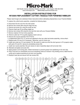
8. Connect motor junction box wires, as shown
in Figure 10.
9. Attach motor junction box cover and re-attach
base cabinet front panel.
10. Follow Test Run steps on Page 18.
GND
PE
VU W
W2
V2U2
W1
W5
V1
V5
U1
U5
Motor
3 Phase
440V
Hydraulic Actuator
Wilson Co.
AC24 Directional
DSG-02-3C60-A2-N
Stop Valve
JUNWAV
ST-02-180
Hydraulic Cylinder
Lian Her Cylinder
LHC-FA-1412
100 x 55
Pressure Gauge
1811
9 17
TopBottom
To Control Box
AC 24V
AC 24V
Figure 10. 440V motor junction box wiring.
7. Remove any installed 220V cord and plug.

Model G0805 (Mfd. Since 1/16)
-15-
SECTION 3: SETUP
Description Qty
• Safety Glasses (for each person) ............... 1
• Gloves (for each person) ............................ 1
• Cleaner/Degreaser (Page 26) .................... 1
• Shop Rags .................................................. 1
• Lifting Strap/Chain
(Rated for at least 1200 lbs.) ...................... 1
• Lifting Equipment
(Rated for at least 1200 lbs.) ...................... 1
• Steel Lifting Shackle
(Rated for at least 1200 lbs.) ...................... 1
• Another Person .......................................... 1
Needed for Setup
This machine was carefully packaged for safe
transport. When unpacking, separate all enclosed
items from packaging materials and inspect them
for shipping damage.
If items are damaged
,
please
call us immediately at (570) 546-9663.
IMPORTANT:
Save all packaging materials until
you are completely satisfied with the machine and
have resolved any issues between Grizzly or the
shipping agent. You MUST have the original pack-
aging to file a freight claim. It is also extremely
helpful if you need to return your machine later.
Unpacking
SUFFOCATION HAZARD!
Keep children and pets away
from plastic bags or packing
materials shipped with this
machine. Discard immediately.
This machine presents
serious injury hazards
to untrained users. Read
through this entire manu-
al to become familiar with
the controls and opera-
tions before starting the
machine!
Wear safety glasses and
gloves during the entire
setup process!
HEAVY LIFT!
Straining or crushing injury
may occur from improperly
lifting machine or some of
its parts. To reduce this risk,
get help from other people
and use a forklift (or other
lifting equipment) rated for
weight of this machine.
The following items are needed, but not included,
for the setup/assembly of this machine.

-16-
Model G0805 (Mfd. Since 1/16)
Inventory Cleanup
The unpainted surfaces of your machine are
coated with a heavy-duty rust preventative that
prevents corrosion during shipment and storage.
This rust preventative works extremely well, but it
will take a little time to clean.
Be patient and do a thorough job cleaning your
machine. The time you spend doing this now will
give you a better appreciation for the proper care
of your machine's unpainted surfaces.
There are many ways to remove this rust preven-
tative, but the following steps work well in a wide
variety of situations. Always follow the manufac-
turer’s instructions with any cleaning product you
use and make sure you work in a well-ventilated
area to minimize exposure to toxic fumes.
Before cleaning, gather the following:
• Disposable rags
• Cleaner/degreaser (WD•40 works well)
• Safety glasses & disposable gloves
• Plastic paint scraper (optional)
Basic steps for removing rust preventative:
1.
Put on safety glasses.
2.
Coat the rust preventative with a liberal
amount of cleaner/degreaser, then let it soak
for 5–10 minutes.
3.
Wipe off the surfaces. If your cleaner/degreas-
er is effective, the rust preventative will wipe
off easily. If you have a plastic paint scraper,
scrape off as much as you can first, then wipe
off the rest with the rag.
4.
Repeat Steps 2–3 as necessary until clean,
then coat all unpainted surfaces with a quality
metal protectant to prevent rust.
NOTICE
Avoid chlorine-based solvents, such as
acetone or brake parts cleaner, that may
damage painted surfaces.
Inventory (Figure 11) Qty
A. Miter Bodies ............................................... 2
B. Thickness Gauge 0.25mm ......................... 1
C. Hex Wrench 7mm ....................................... 1
D. Miter Fences ............................................... 2
E. Eye Bolt ...................................................... 1
Figure 11. G0805 inventory.
A
B
The following is a list of items shipped with your
machine. Before beginning setup, lay these items
out and inventory them.
If any non-proprietary parts are missing (e.g. a
nut or a washer), we will gladly replace them; or
for the sake of expediency, replacements can be
obtained at your local hardware store.
C
D
E
NOTICE
If you cannot find an item on this list, care-
fully check around/inside the machine and
packaging materials. Often, these items get
lost in packaging materials while unpack-
ing or they are pre-installed at the factory.

Model G0805 (Mfd. Since 1/16)
-17-
Figure 12. Minimum working clearances.
33"
40"
26"
Wall
30"
Minimum
For Maintenance
Adjustable
Pedestal
Site Considerations
Weight Load
Refer to the Machine Data Sheet
for the weight
of your machine. Make sure that the surface upon
which the machine is placed will bear the weight
of the machine, additional equipment that may be
installed on the machine, and the heaviest work-
piece that will be used. Additionally, consider the
weight of the operator and any dynamic loading
that may occur when operating the machine.
Physical Environment
The physical environment where the machine
is operated is important for safe operation and
longevity of components. For best results, oper-
ate this machine in a dry environment that is
free from excessive moisture, hazardous chemi-
cals, airborne abrasives, or extreme conditions.
Extreme conditions for this type of machinery are
generally those where the ambient temperature
range is outside 41°–104°F; the relative humidity
range is outside 20–95% (non-condensing); or
the environment is subject to vibration, shocks,
or bumps.
Children or untrained people
may be seriously injured by
this machine. Only install in an
access restricted location.
Lighting
Lighting around the machine must be adequate
enough that operations can be performed safely.
Shadows, glare, or strobe effects that may distract
or impede the operator must be eliminated.
Space Allocation
Consider the largest size of workpiece that will
be processed through this machine and provide
enough space around the machine for adequate
operator material handling or the installation of
auxiliary equipment. With permanent installations,
leave enough space around the machine to open
or remove doors/covers as required by the main-
tenance and service described in this manual.
See below for required space allocation.

-18-
Model G0805 (Mfd. Since 1/16)
Lifting & Placing
HEAVY LIFT!
Straining or crushing injury
may occur from improperly
lifting machine or some of
its parts. To reduce this
risk, use a forklift (or other
lifting equipment) rated for
weight of this machine.
To lift and place machine into position:
1. Move shipping crate to work area, and
remove shipping bolts connecting each cor-
ner of machine to pallet.
2. Secure work fence stops and foot pedal
assembly to avoid sudden shifts.
3. Install eye bolt to top of headstock.
4. Attach lifting strap/chain to eye bolt at cen-
ter-top of notcher headstock, as shown in
Figure 13.
Note: It may be necessary to use a metal
shackle when attaching lifting strap to eye
bolt.
Figure 13. Lifting straps through eye bolt.
Eye Bolt
Placement
Lifting
Strap
Metal Shackle
(not included)
5. With another person steadying load to keep
it from swinging, slowly lift machine a few
inches above pallet and ensure table remains
level. Place machine in desired location.
Test Run
Once assembly is complete, test run the machine
to ensure it is properly connected to power and
safety components are functioning correctly.
If you find an unusual problem during the test run,
immediately stop the machine, disconnect it from
power, and fix the problem BEFORE operating the
machine again. The
Troubleshooting
table in the
SERVICE section of this manual can help.
To test run machine:
1. Clear all setup tools away from machine.
2. Press Emergency Stop button on control
pedestal.
3. Install approved 220V plug (see Wiring on
Page 33), or hardwire machine for 440V (see
Voltage Conversion on Page 13).
DO NOT start machine until all preceding
setup instructions have been performed.
Operating an improperly set up machine
may result in malfunction or unexpect-
ed results that can lead to serious injury,
death, or machine/property damage.
Serious injury or death can result from
using this machine BEFORE understanding
its controls and related safety information.
DO NOT operate, or allow others to operate,
machine until the information is understood.
Always ensure fluid reservoir is filled to
appropriate level before each use!
The Test Run consists of: 1) Emergency Stop
button functions, 2) Verifying machine powers-up
properly, and 3) Machine properly switches from
AUTO to MANU (manual) mode.
/