
Please read through and understand these instructions before attempting disassembly of your Powered Nibbler.
To replace the cutter/nozzle assembly, complete the following steps:
A. Disconnect the line cord from the wall socket.
B. Remove two screws #35 using the large hex key.
C. Remove set screw #31 using the small hex key.
D. Remove head cap #2 by pulling straight up.
E. Remove two screws #34 using the hex key that came with your Powered Nibbler.
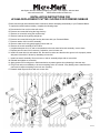
F. Remove retainer #15 from drive assembly.
G. Remove cutter bar #14 by gently tapping it down and out.
H. Remove the nozzle assembly #16/17/18/19.
I. If replacement parts #13, 15, and 34 are attached to the new cutter bar/nozzle assembly, remove them.
J. Replace parts #12 and #13 if necessary. Otherwise, save for future use.
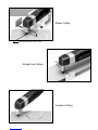
K. Install new cutter bar #14 and retainer #15. Be careful to make sure that the short groove in #14 properly mates
with parts #13 and #15. Secure by reinstalling screws #34.
L. Install new nozzle assembly. Be sure recess on side of assembly aligns with set screw hole.
M. Reinstall and tighten set screw #31.
N. Apply grease to all moving parts. Shield mechanism to prevent grease from splattering in the next step.
O. Plug in tool and run momentarily to be sure everything works as it should. If any binding occurs, determine the
cause and re-adjust everything so the tool runs smoothly.
P. Reattach head cap and secure with two screws #35.
MM123004
INSTALLATION INSTRUCTIONS FOR
#81556A REPLACEMENT CUTTER / NOZZLE FOR POWERED NIBBLER
340 Snyder Avenue, Berkeley Heights, NJ 07922 • Tech Support: 908-464-1094
www.micromark.com [email protected]

-
 1
1
-
 2
2


Ask a question and I''ll find the answer in the document
Finding information in a document is now easier with AI
Related papers

Other documents
-
Chicago Electric 94782 Assembly And Operation Instructions Manual
-
Power Fist Air Nibbler User manual
-
Draper D20 20V Brushless Nibbler Operating instructions
-
Harbor Freight Tools 96661 Owner's manual
-
Central Pneumatic Item 96661-UPC 193175272614 Owner's manual
-
Grizzly G0804 Owner's manual
-
-
-
Hitachi DS18DVB2 User manual
-
Hitachi 93221816 Datasheet