Zoeller 1452-0008 Operating instructions

Category
Water pumps
Type
Operating instructions

This manual is also suitable for

Validation code: LB659498
Serial Number
Purchase Date
Questions, problems, missing parts? Before returning to your retailer, call our customer
service department at 1-800-584-8089, 7:30 a.m. - 5:00 p.m., EST, Monday - Friday.
ATTACH YOUR RECEIPT HERE
4 IN. SUBMERSIBLE WELL PUMP
2 WIRE, 115 V MODEL: #1450-0010
2 WIRE, 230 V MODELS: #1450-0011, 1451-0007,
1452-0006, 1452-0008, 1453-0004
Zoeller
®
is a registered trademark
of Zoeller Co. All Rights Reserved.
025095 C
Español p. 22
2
PRODUCT SPECIFICATIONS
Please read and understand this entire manual before attempting to assemble, operate or install the
product.
NOTE: Pumps with the “UL” Mark and pumps with the “US” mark are tested to UL Standard
UL778.CSA certied pumps are certied to CSA Standard C22.2 No. 108. (CUS)
ELECTRICAL SHOCK HAZARD
Always disconnect power source before performing any work on or near the motor or its connected
load. If the power disconnect point is out-of-sight, lock it in the open position and tag it to prevent
unexpected application of power. Failure to do so could result in fatal electrical shock.
ELECTRICAL SHOCK HAZARD
Do not handle the pump with wet hands or when standing in water as fatal electrical shock could
occur. Disconnect main power before handling unit for ANY REASON!
RISK OF ELECTRIC SHOCK
These pumps have not been investigated for use in swimming pool areas.
ELECTRICAL SHOCK HAZARD
Can shock, burn or cause death. Ground pump before connecting to power supply.
ELECTRICAL SHOCK HAZARD
The pump is intended for use in a well. Motor frame must be connected to power supply ground or
fatal electrical shock may result.
ELECTRICAL SHOCK HAZARD
NEVER leave fused disconnect switch or pressure control switch cover or covers open (either
partially or completely) when not being worked on by a qualied electrician or repairman.
SAFETY INFORMATION
Pump Performance Chart
ITEM # HP GPM
PUMPING DEPTH IN FEET - CAPACITIES IN GALLONS PER
MINUTE AT 40 PSI
(PRESSURE PER SQUARE INCH)
20 40 60 80 100 125 150 175 200 250 300 325
1450-0010 1/2 12 11.5 10.6 9.5 8.7 7.3 6.8
1450-0011 1/2 12 11.5 10.6 9.5 8.7 7.3 6.8
1451-0007 3/4 12 13.1 12.5 12.0 11.4 10.8 10.0 9.2 8.3 6.9 4.1
1452-0006 1 12 13.8 13.4 12.9 12.5 12.0 11.6 11.0 10.0 9.5 7.8 5.9 6.2
1452-0008 1 18 22.4 21.1 19.7 18.3 16.7 14.9 12.4
1453-0004 1 26 27.9 24.9 22.9 18.9 14.9 4.9
NOTE: Pump capacity in GPM should equal the total number of water fixtures in the home. If you
have 3 bathroom fixtures x 2 bathrooms, plus 3 fixtures in the kitchen and 1 outside fixture, the total
fixture count is 10. Your pump should provide 10 GPM per the chart above. Typical 3 - 4 bedroom
homes require 8 - 12 GPM.
DANGER
3
WARNING
ELECTRICAL SHOCK ALERT
Follow all local electrical and safety codes, as well as the National Electrical Code (NEC) and the
Occupational Safety and Health Act (OSHA).
ELECTRICAL SHOCK ALERT
All electrical wiring or service should be done by a qualied electrician.
EXPLOSION ALERT
Do not use to pump ammable or explosive uids such as gasoline, fuel oil, kerosene, etc. Do not use
in ammable and/or explosive atmospheres.
HAZARDOUS PRESSURE ALERT
Install pressure relief valve in discharge pipe. Release all pressure on system before working on any
component.
CHEMICAL ALERT.
Prop65 Warning for California residents:
WARNING: Cancer and Reproductive Harm - www.P65Warnings.ca.gov
CAUTION
ELECTRICAL SHOCK MAY OCCUR
Wire motor for correct voltage. See Electrical section and motor nameplate.
ELECTRICAL SHOCK MAY OCCUR
Ground motor and controls before connecting to power supply.
ELECTRICAL SHOCK MAY OCCUR
Follow wiring instructions in this manual when connecting to power lines.
ELECTRICAL SHOCK MAY OCCUR
Protect power cable from nicks or cuts from sharp objects or scraping on well casing when lowering
pump into well. Do not allow it to come into contact with oil, grease, hot surfaces or chemicals.
ELECTRICAL SHOCK MAY OCCUR
The motor voltage and phase indicated on the motor nameplate should be checked against the actual
electrical supply. Check your power source. Check electrical supply for correct fusing, wire size, and
adequate grounding and transformer size.
PRODUCT DAMAGE MAY OCCUR
The power supply for a submersible pump should be a separate circuit, independent of all other
circuits. It must be equipped with a fuse box of ample capacity.
PRODUCT DAMAGE MAY OCCUR
Shut o power source when voltage drops 10% below rated voltage of motor.
FIRE SAFETY
For re protection, power supply should be free of any building, preferably on a direct line from
transformer. In event of re, wires will not be destroyed and water supply not cut-o.
NOTE: Install all electrical equipment in protected area to provide adequate ventilation for pressure
switch and controls to prevent moisture damage to components.
NOTE: Install pump, pressure tank, pitless adaptor or well seal in accordance with state and local
plumbing codes.
4
PREPARATION
Before beginning installation of product, make sure all parts are present. Compare parts with package
contents drawing. If any part is missing or damaged, do not attempt to assemble the product. Contact
customer service for replacement parts.
Estimated Installation Time: 2 hours.
Tools Required for Installation: Hacksaw, screwdriver, pliers, pipe vise, pipe wrenches (2), wire
cutters, wire strippers/crimpers, adjustable wrench (medium-large), Ohmmeter, propane torch, knife
or round le, small weight.
Materials Required for Installation: Submersible pump cable, power cable, pressure tank, shrink
tube & butt connectors, 1-1/4 in. check valve, torque arrestor, hose clamps, pipe ttings, pitless
adaptor or well seal, pressure switch, pressure gauge, pressure relief valve, tank cross, 1/4 in.
minimum safety rope, electrical tape,. You will also need either enough 1-1/4 in. Schedule 80 PVC pipe
to reach 20 ft. below the static level or 20 ft. below the drawdown level of your well, or coiled poly pipe
rated for 160 PSI. Poly pipe cannot be used for installations any deeper than 200 ft.
Optional Materials: 1-1/4 in. male barbed adaptor for use with poly pipe, cable guards to protect wire
inside the well, thread tape and thread paste.
Submersible Pump Cable and Power Cable Selection
Check cable size against Submersible Wire Size Chart below. Submersible power cable must be UL
listed for submersible pump applications. For Canadian installations, type RWU, TWU, SGOW or
SWOW power supply cable is recommended. Cable is selected for the maximum pump setting plus the
offset distance to the service entrance.
IMPORTANT: Use of wire sizes smaller than those specified in the chart will cause low starting
voltage, may cause early pump failure and will void the warranty. Larger wire sizes may always be used
for better economy of operation. Be sure voltage at pressure switch or fuse is between the following
limits:
115V Rated - Between 104 & 127 volts
230V Rated - Between 210 & 250 volts
NOTE: A small AWG number, i.e. 10 Ga., is larger in diameter than a large AWG number, i.e. 14 Ga.
The National Electric Code (NEC 250-43) requires a separate ground wire be run down the well to the
submersible pump and connected to all exposed metal parts of the pump and motor. Refer to the most
recent National Electric Code (NEC) Article 250 (grounding) for additional information.
NOTE: All wiring should be done by a qualified electrician.
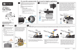
DESCRIPTION QUANTITY
Pump 1
PACKAGE CONTENTS
5
Submersible Cable and Ground Wire
Selection
WARNING: Turn o power at the electrical
service box before starting installation.
Finding the Depth of Your Well:
1. Tie a small, heavy weight to the end of a
cord (make sure the cord is at least 350 ft.
long). Lower this weight into the well until
it reaches the bottom. Take up any slack
and mark the string at ground level. Pull the
string from the well and measure from the
weight to your mark. This is the depth of your
well. Subtract 10 ft. from your well depth.
See Performance chart on page 2 to be sure
pump is rated for this depth. (Fig. 1)
Drawdown
Water Level
10 Ft. Min.
20 Ft.
Top of Well Screen
Bottom of Well
1
2
2. Drawdown is the lowest water level in the
well after the pump is turned on. If you know
the drawdown, the pump can be set 20 feet
below this level. However, the bottom of the
motor should be at least 10 feet from the top
of the well screen. (Fig. 2)
CAUTION: If your pump depth is
200 ft. or more, you may want to consider
contacting a professional well pump
installer. Piping lled with water, along with
the weight of the pump, will be very heavy.
Be sure to have assistance during pump
installation.
MINIMUM WIRE SIZE CHART (GUAGE) - COPPER WIRE
HP VOLT
Maximum Cable Length In Feet Using AWG Cable*
#14 #12 #10
1/2 110/115 100 160 250
1/2 230 400 650 1020
3/4 230 300 480 760
1 230 250 400 630
*NOTE: Wire length is the total distance from power source to pump depth.
6
ASSEMBLY INSTRUCTIONS
NOTE: Schedule 80 PVC pipe (sold separately) is recommended. If you use black poly pipe (sold
separately), the pipe must be rated for 160 PSI and be no longer than 200 ft.
NOTE: The pump must be assembled with piping on the ground before lowering into the well. Lay out
all necessary materials near the well.
NOTE: All threaded joints and connections should have thread tape (not included) applied, tightened
securely with a pipe wrench (not included) and then tightened an additional 1/4 turn.
Follow step 1a and 1b below for Schedule 80
pipe or step 2a and 2b for black poly pipe.
Schedule 80 pipe (recommended)
1a. Apply thread tape and then thread the
pipe directly into the pump discharge and
tighten. For 1 in. pipe, you will also need a
1-1/4 in. x 1 in. reducer bushing, not shown.
(Fig. 1a)
Schedule
80 Pipe
Torque
Arrestor
1a
1b
1b. Slide the two hose clamps packaged with
the torque arrestor (sold separately) over
the end of a short piece of Schedule 80
pipe (approximately 4 ft. long). The pump
will be easier to handle if a short piece is
installed rst. Continue to Step 3.
(Fig. 1b)
7
Black poly pipe
2a. Apply thread tape and thread a 1-1/4 in.
male barbed adaptor (sold separately) into
the top of the pump and tighten. If using
1 in. black poly pipe, install a 1-1/4 in. x 1
in. reducer bushing (sold separately) as
shown. (Fig. 2a)
IL1171
1-1/4 in.
male
barbed
adapter
1-1/4 in x
1 in.
reducer
bushing
2a
IL1172
Torque
Arrestor
Approx. 4 ft.
2b
3
2b. Clamp pipe onto barbed end of male
adaptor with two hose clamps (sold
separately). (Fig. 2b)
3. Firmly clamp the torque arrestor to the pipe
approximately 2 to 4 ft. above the pump,
using the two clamps provided with the
torque arrestor. (Fig. 3)
8
4. Typical installations include the following
components. Purchase these items
separately depending on your need. (Fig. 4)
Discharge pipe - delivers water to home
Well seal or pitless adapter - keeps debris out
of well
Safety rope - prevents pump from falling
Check valve - keeps water in pipe
Electrical cable - connects to house electricity
Torque arrestor - keeps pump stable
Drop pipe - connects pump to discharge
Well casing - holds all components
Discharge Pipe
Spring-Loaded Check Valve
(Recommended every 100 ft.)
Safety Rope
Well Seal or Pitless Adapter
Well Casing
Torque Arrestor
Drop Pipe
Electrical Cable (Secured to drop
pipe with tape or clamps every
10 ft.)
4
ELECTRICAL HOOKUP AT THE PUMP
Submersible Cable Splicing
Pump is equipped with a lead wire assembly with 2 black and 1 green wire. The length of wire
needed to attach to this lead wire assembly is equal to the distance from the pump in the well to
the top of the well. Additional wire will be needed to run from the top of the well to the house.
CAUTION: Follow instructions carefully to make a watertight splice. A leak in the splice can result
in pump damage, blown fuses, overload protector tripping or electric shock hazard.
Shrink tube
1
Splicing instructions
1. Slide one black shrink tube from a heat
shrink splice kit (sold separately) over each
wire (including the green ground wire)
coming out of the pump. (Fig 1)
9
Metal Connector
2
2. NOTE: For each wire coming out of the
pump, including the green ground wire, slide
the wire from the pump into one end of a
metal connector from the splicing kit. Then
slide stripped end of wire from electrical
cable into other end of metal connector.
Connector should be centered over both
wires. Squeeze metal connector until it
closes tightly over both wire ends.
(Fig 2)
IL1145
Shrink tube
Metal Connector
ON
OFF
IL1146
3
4
3. Slide one shrink tube over each crimped
joint. (Fig 3)
4. Hold a torch (not included) approximately 6
in. from the center of the tubing and move it
back and forth. Heat one set of wiring tubing
at a time until seal is completed. During the
heating process, keep all other wires/tubing
away from heat to prevent melting together.
Avoid overheating, as this may make the
tubing brittle. When liquid oozes from end of
tube, seal should be complete. (Fig 4)
CAUTION: Do not lift pump by power
cable or motor leads! Damage to cable or leads
will result.
10
5
Securing wires to pipe
5. Tape electrical cable to the pipe about every
ten feet. Use a minimum of two wraps of
tape to allow the cable to move slightly. Tape
spliced connections to the pipe to eliminate
rubbing against the well casing. A cable
guard or plastic zip ties may also be used.
(Fig 5)
Ground Wire Installation (REQUIRED)
DANGER: The green ground wire from
Pump motor must be connected to power
supply ground or fatal electrical shock may
result.
INSTALLATION INSTRUCTIONS
Lowering Pump Into Well
CAUTION: If your pump depth will be
200 ft. or more, you may want to consider
contacting a professional well pump
installer. Piping lled with water, along with
the weight of the pump, will be very heavy.
Be sure to have assistance during pump
installation.
REMINDER: Pump and all piping must be
assembled and securely connected before the
assembly is lowered into the well.
1. Tie one end of safety rope (sold separately)
securely to pump safety eyelet and the other
end to the well cap. This is your only security
against losing the pump down the well. (Fig
1)
CAUTION: Be sure the top edge of the
well casing is perfectly smooth. Sharp or jagged
edges can cut or scrape the cable and cause a
short. Do not let the cable drag over the edge
of the well casing since this may cause damage
to the insulation.
2. Lower pump to approximately 20 ft. below
maximum drawdown of the water or a
minimum of 10 ft. o the bottom. Do NOT set
pump on bottom of well. (Fig 2)
Safety
Rope
Drawdown
Water Level
10 Ft. Min.
20 Ft.
Top of Well Screen
Bottom of Well
1
2
11
3. Use a pipe vise (not included) to prevent the
pump and pipe from dropping into the well.
(Fig 3)
3
IL1148
4a
4a. Pitless Adaptor Installation. Pitless adaptor
should be installed below the frost line, and
on the side of the well casing where the
supply line will run from well, in accordance
with the manufacturer’s instructions.
NOTE: Pitless adaptor models vary according
to each application. (Fig. 4a)
4. Add a well seal or pitless adaptor (sold
separately) to allow for the pipe to be
connected to house service.
Pitless
Adaptor
Installation
Below
Frost Line
Well Seal
Installation
At Top of
Well Casing
OR
4
12
4b
4b. Well Seal Installation: After the pump
assembly is lowered into the well, mount
the well seal onto the well casing and
tighten the four bolts in the well seal evenly.
PRELIMINARY TEST RUN
Fuse Box
Outside
Faucet
Pump in
Well
Outside
Faucet
Pump in
Well
WARNING: All electrical wiring or service
should be done by qualied electrician. Be sure
to test cable for continuity with an ohmmeter
before starting the pump.
1. All wells should be ushed clear before
allowing water into the house. (Fig. 1)
2. Open an outside faucet and allow water
to run until water is clear of sand or any
other impurities. If an outside faucet is not
available, place softener in bypass position,
remove aerator from a high-ow faucet
and allow water to run until it is clear of
impurities. Once clear, turn o water ow,
replace aerator and put softener back into
service position. (Fig. 2)
CAUTION: Be sure you do not stop pump
before water runs clear. This may take several
hours. If pump stops with sand in it, it may lock.
1
2
13
Drawdown
Water Level
10 Ft. Min.
20 Ft.
Top of Well Screen
Bottom of Well
3. If pump lowers water in the well far enough
to lose prime, either lower pump in the
well (if possible) or throttle (slow down) the
discharge of the well with the gate valve to
match the capacity of the well. (Fig. 3)
NOTE: If the well is low capacity, use a low
water level control.
3
PRESSURE TANK INSTALLATION INSTRUCTIONS
1
2
The purpose of the pressure tank (sold
separately) is to allow a certain amount of
water to be used before the pressure drops
enough to cause the pump to start. Without a
pressure tank, the pump would start and stop
constantly, every time water is used.
NOTE: Use thread tape and thread paste on all
threaded connections.
1. NOTE: Check the air pressure of the tank
with a tire gauge (sold separately) before the
system is charged with water. The pressure
should be 2 lbs. less than the low pressure
cut in on the pressure switch. For instance,
for a 30-50 switch, set the tank pressure at
28 lbs. or less. (Fig. 1)
2. Apply ve wraps of thread tape and thread
paste, insert a tank tee (sold separately)
through the opening in the bottom of the
pressure tank, and tighten securely. (Fig. 2)
14
4. Connect a 3/4 in. pipe (sold separately) and
union (sold separately) to the 3/4 in. tting.
(Fig. 4)
5. Connect elbows, additional pipe and ball
valve (all sold separately) as needed for your
particular installation. (Fig. 5)
IL1154
Glue
Glue
4
5
IL1153
Tape
3
3. Connect a 3/4 in. tting (sold separately) to
the 3/4 in. opening on the pipe tee. (Fig. 3)
15
6. Connect a drain valve (sold separately) to
one of the 1/2 in. openings in the tank tee.
(Fig. 6)
IL1156
Tape
6
WARNING: Not providing a relief valve
can cause extreme overpressure that could
result in personal injury and/or property
damage.
A properly sized pressure relief valve must be
installed on any installation where the pump
pressure can exceed the pressure tank’s
maximum working pressure or on systems
where the discharge line can be shut o or
obstructed. The relief valve drain port should be
piped to a drain.
7. Attach the pressure relief valve (sold
separately) to the remaining 1/2 in. opening
in the tank tee. (Fig 7)
8. To connect the pressure tank to the pump,
begin by threading a 1 in. coupling (sold
separately) onto the pipe tee. (Fig. 8)
IL1157
10
20
30
40
50
60
70
80
IL1158
Tape
7
8
16
WARNING: This equipment is intended for installation by a technically qualied electrician.
Failure to install it in compliance with national and local electrical codes may result in electrical shock
or re hazard, unsatisfactory performance, and equipment failure.
WARNING: Always disconnect power source before working on or near the pump, its connected
load and wiring. If the power disconnect is out of sight, lock it in the open position and tag to prevent
unexpected application of power.
NOTE: Pump is a 2-wire pump. No control box is required. Model UT200 is 115-volt. All other models
require 230-volt service.
ELECTRICAL HOOKUP FROM THE HOUSE TO PUMP AND PRESSURE TANK
9. Add additional couplings, unions and pipe (all
sold separately) as necessary to reach the
pump. (Fig. 9)
NOTE: Schedule 80 pipe recommended
10
20
30
40
50
60
70
80
Schedule 80 Pipe Shown
9
1. Determine proper voltage from breaker box
(sold separately) to pressure switch. (Fig. 1)
IL1170
1
17
2. Remove cover from pressure switch and
screw the switch into the 1/4 in. opening on
the top of the pipe tee. (Fig. 2)
2
L4
L1
L4
L1
3. Thread the cable from the house electrical
service through one of the holes in the side
of the pressure switch and tighten down the
electric wire strain relief.
CAUTION: Do not crush wire. (Fig. 3)
IL1162
L4
L1
Strain Relief
3
4. Connect the two wires from the house
electrical service to the outside pressure
switch terminals (L1 and L4). (Fig. 4)
4
18
L3
L2
IL1167
L2
L3
6. Connect the two wires from the pump to the
inside pressure switch terminals (L2 and L3).
(Fig. 6)
6
Ground Screws
From
Pump
From
Power Source
7
7. Connect green ground wires from the pump
cable and the house electric cable to the two
ground green screws on base of pressure
switch. Replace switch cover.
(Fig 7)
IL1165
5. Thread the cable from the pump through the
remaining hole in the side of the pressure
switch and tighten down the electric wire
strain relief.
CAUTION: Do not crush wire.
5
19
TROUBLESHOOTING
PROBLEM POSSIBLE CAUSE CORRECTIVE ACTION
Fuses blow 1. Incorrect voltage at motor 1. Check for correct wire size.
Replace undersize wire. Check
line voltage, contact power
company if voltage is incorrect
2. Defective fuse box or incorrect fuses 2. Inspect fuse box wiring and
correct.
Install the proper fuses
3. Defective pressure switch 3. Replace pressure switch or
clean contacts
4. Defective drop cable insulation 4. Check drop cable insulation
resistance. Pump must be
pulled to replace defective
cable
5. Motor malfunction 5. Check motor winding
resistance. Pump must be
pulled to replace defective
motor
6. Pump malfunction 6. If all above checks are good,
then pump is probably bound.
Pump must be pulled. Check
for sand or pump shaft
misalignment. Correct well
condition if sand is the problem
Motor won’t start.
Fuses don’t blow
1. No power to start motor 1. Check voltage at line side
of fuse box. Contact power
company if no power is
reaching box. Check voltage
at load side of fuse box and at
other control devices in circuit.
Make necessary corrections
2. Defective drop cable or motor 2. Check motor winding
resistance. Pump must be
pulled to replace defective
cable or motor
20
PROBLEM POSSIBLE CAUSE CORRECTIVE ACTION
Motor runs, but
delivers little or no
water
1. Air locked pump 1. Normal delivery may resume
if water pump is started and
stopped at one minute intervals
2. Gas or air in well water 2. Connect hose to service
valve. Run water thru hose
submerged in water in clear
jar. Observe for air bubbles
from hose outlet. If tank is
standard type, the air volume
control may be defective -
replace; otherwise, have well
checked for proper water level
as pump may be drawing air.
Lower pump and/or correct well
condition
3. Low water level in well or pumping
too much from well
3. Throttle pump with gate valve.
Lower pump setting if depth of
well is adequate
4. Defective or improperly installed
check valve
4. Pump must be raised to replace
or reinstall correctly
5. Leak in drop pipe damaged section 5. Raise pump, check pipe for
leak and replace
6. Pump inlet screen blocked 6. Raise pump and clean screen.
Verify that well is clean. Reset
pump at less depth if possible
7. Worn pump 7. Pull pump and replace
damaged components
8. Broken pump shaft or motor shaft or
worn coupling
8.
Pull pump, inspect shafts and
coupling for damage. Replace
defective components
Pump operates
properly, but won’t
shut off
1. Pressure switch 1. Readjust switch to lower shut
off pressure setting, clean
contacts or replace switch
2. Low water level 2. Throttle pump outlet at gate
valve or readjust pressure
switch to lower shutoff pressure
setting
3. Leak in drop pipe or worn pump 3. Throttle pump output at gate
valve or readjust pressure
switch to lower shut off
pressure setting. If pump does
not shut off, pump must be
raised and defect repaired
  • Page 1 1
  • Page 2 2
  • Page 3 3
  • Page 4 4
  • Page 5 5
  • Page 6 6
  • Page 7 7
  • Page 8 8
  • Page 9 9
  • Page 10 10
  • Page 11 11
  • Page 12 12
  • Page 13 13
  • Page 14 14
  • Page 15 15
  • Page 16 16
  • Page 17 17
  • Page 18 18
  • Page 19 19
  • Page 20 20
  • Page 21 21
  • Page 22 22
  • Page 23 23
  • Page 24 24
  • Page 25 25
  • Page 26 26
  • Page 27 27
  • Page 28 28
  • Page 29 29
  • Page 30 30
  • Page 31 31
  • Page 32 32
  • Page 33 33
  • Page 34 34
  • Page 35 35
  • Page 36 36
  • Page 37 37
  • Page 38 38
  • Page 39 39
  • Page 40 40
  • Page 41 41
  • Page 42 42
  • Page 43 43
  • Page 44 44

Zoeller 1452-0008 Operating instructions

Category
Water pumps
Type
Operating instructions
This manual is also suitable for

Ask a question and I''ll find the answer in the document

Finding information in a document is now easier with AI

in other languages