Page is loading ...

Page 1
INSTALLATION INSTRUCTIONS FOR LOW AMBIENT KIT
USED ON KG/KC/KH/KD PACKAGED ROOFTOP UNITS
506335-03
2/2018
Supersedes 506335-02
©2017
LOW AMBIENT KIT
PACKAGED UNITS KITS
AND ACCESSORIES
Shipping and Packing List
14D89 & 14D96
Package 1 of 1 contains:
1- Pressure switch (S11)
2- Wire harnesses
1- Relay (K10 or K58)
1- Screw
1- Valve depressor tee
54W16
Package 1 of 1 contains:
2- Pressure switches (S11, S84)
2- Wire harnesses
14N31
Package 1 of 1 contains:
3- Pressure switches (S11, S84, S185)
1- Wire harness
15C84
Package 1 of 1 contains:
2- Pressure switches (S11, S185)
2- Relays (K58, K159)
1- Wire harness
1- Valve depressor tee
CAUTION
As with any mechanical equipment, contact with
sharp sheet metal edges can result in personal in
jury. Take care while handling this equipment and
wear gloves and protective clothing.
WARNING
Improper installation, adjustment, alteration, ser
vice or maintenance can cause property damage,
personal injury or loss of life. Installation and ser
vice must be performed by a licensed professional
HVAC installer or equivalent, service agency, or the
gas supplier
Application
See table 1 for usage.
TABLE 1
Box Unit Cat. # LB #
AKG/KC 024-090 14D89 LB-107318BT
AKH 024-074S 14D96 LB-107318BR
A KHB/KDB 024-060H 15C84 603364-31
BKG/KC 092-150,
KHA 092S-150S 54W16 603364-06
BKHB/KDB 092H-122H 14N31 603364-30
The low ambient pressure switches cycle the outdoor fan
while allowing compressor operation in the cooling cycle.
This intermittent fan operation results in a high
evaporating temperature which allows the system to
operate without icing the evaporator coil and losing
capacity. This kit is designed for use in ambient
temperatures no lower than 0°F (-17.8°C) unless
otherwise noted in the Engineering Handbook.
Install a belly-band style crankcase heater on compressors
which don't have one.
Install Pressure Switch
1- Disconnect power to unit.
2- Refer to table 2 for figure number showing switch
location. Open appropriate unit panel.
3- 024-090 Units -
Install the valve depressor tee on the liquid line
pressure tap. See figure 1 and 2.
4- Install pressure switches on liquid line pressure taps
or valve depressor tee.
5- Check system for leaks.
TABLE 2
Unit Switch Location
KG/KC 024-090
KH 024-074S Figure 1
KD/KH 024-060H Figure 2
KG/KC 092-150,
KHA 092S-150S Figure 3
KHB/KDB 092H-122H Figure 4

Page 2
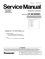
PRESSURE SWITCH LOCATION
KG/KC 024-090 & KH 024-074S
SCROLL COMPRESSORS
S11
PRESSURE
SWITCH
FIGURE 1
LIQUID LINE
PRESSURE
TAP
VALVE
DEPRESSOR
TEE
PRESSURE SWITCH LOCATION
KH/KD 024-060H SCROLL COMPRESSORS
VALVE
DEPRESSOR
TEE
FIGURE 2
S11 AND S185
PRESSURE
SWITCH
LIQUID LINE
PRESSURE
TAP
PRESSURE SWITCH LOCATION - KG/KC 092-150 AND KHA 092S-150S UNITS
S84
PRESSURE
SWITCH
S11
PRESSURE
SWITCH
FIGURE 3
Note - KGA/KCA shown;
pressure switches are in the
same location in KHA units.

Page 3
PRESSURE SWITCH LOCATION - KHB/KDB 092H-122H UNITS
S84
PRESSURE
SWITCH
S11
PRESSURE
SWITCH
FIGURE 4
S185
PRESSURE
SWITCH

Page 4
Install Relay - KG/KC 024-090, KH 024-074
1- Install the relay in units shown in table 3. Refer to
figure 5 for KG/KC and KH standard efficiency unit
relay location. Refer to figure 6 for KH/KD high
efficiency relay location. Secure with screws
provided in kit.
TABLE 3
Unit Wiring Diagram Key No.
KG/KC
024-090 Y & P Volt Relay not required; discard.
KG/KC
036-090 M, G & J Volt* K10
KH 024-074S K58
KH/KD 024-060H K58, K159
*Caution - Pressure switch is not rated for applications above
240V. Relay must be used in high voltage applications.
RELAY LOCATION - KG/KC 036-090,
KH 024-074S UNITS
(ABOVE COMPRESSORS)
K10
OUTDOOR FAN RELAY
KG/KC 036-090
M, G, & J VOLT UNITS
K58
LOW AMBIENT
KIT RELAY
KH 024-074S UNITS
FIGURE 5
A3 - Gas
Units
C1
K72
K58
N
K3
K1
TB1
T1
Control Panel
K10
T3 T4
DL46
CMC1 -
Heat Pump
Units
K220
DL3
K239
K8
K250/
K191
DL50/
DL48
K37 S42
RELAY LOCATION - 024-060H UNITS
(ABOVE COMPRESSORS)
K72, K27 DUAL FUEL
GAS HEAT CONTROL
KD 024-060 P, Y, G, J, M
VOLT UNITS
K58, 159
LOW AMBIENT KIT
RELAY KH/KD
024-060H UNITS
FIGURE 6
A3 - Gas
Units
C5
K72
K58
K3
K1
TB1
T1
Control Panel
K10
T3 T4
DL46
CMC1 -
Heat Pump
Units
K220
DL48
K191
K8
K250
DL50
K37
K27
K159
N

Page 5
Wiring - 024-090 Units
TABLE 4
024-090 UNIT WIRING
Kit Unit Wiring Notes Reference Diagram
14D89 KG/KC 024-060 P Volt
KG/KC 036-090 Y Volt Figure 7 Discard relay and longer harness. P volt - 537780
Y volt - 537777
14D89 KG/KC 036-090 G, J, M Volt Figure 8 All kit components used. 537777
14D96 KH 024-074S P, Y Volt Figure 9 &
Figure 11*
P, Y volt units do not use K10. Figure 9
shows the multi-wire harness.
P volt - 537780
Y volt - 537777
14D96 KH 036-074S G, J, M Volt Figure 10 &
Figure 11* Figure 10 shows the multi-wire harness. 537779
15C84 KD/KH 024-060H P, Y, G, J, M Volt Figure 12 One harness 537855-537858
*Two-wire harness shown.
1- Wire pressure switches. Refer to table 4 for
appropriate wiring diagram. Wires are stamped as
shown in each figure.
2- Bundle wiring and secure away from unit
components.
WIRING - KG/KC 024-090 P, Y VOLT UNITS
K1
S11
J35-2
S11
J35
2
S11
Disconnect
wire to K1-T2
contactor
Connect to
harness wire
marked K1-T2
SHORTER KIT WIRE HARNESS
K1-T2
L1 L2 L3
T1 T2 T3
FIGURE 7
K1-T2
K1-T2

Page 6
WIRING - KG/KC 036-090 G, J, M VOLT UNITS
S11
K1 Disconnect this
wire from K1-T2
L1 L2 L3
T1 T2 T3
AB
K10
12 3
45 6
78 9
AB
AB
K3
K10-A
K10-B
K10-7
K10-5
K3-B
S11S11
K1-A
K1-T2 K1-T2 K1-T2
FIGURE 8
J35
2

Page 7
WIRING - KH 024-074S P, Y VOLT UNITS
MULTI-WIRE HARNESS
S11
Disconnect this wire
from K1-T2
12 3
45 6
78 9
AB
K58
K10-A
S11S11
K1-T2
K58-7 K58-2
K10-A/
CMC1-FAN
FIGURE 9
J35
2
K1
L1 L2 L3
T1 T2 T3
AB
Note - P volt
contactors
have two poles
CMC1 K1
FAN
WIRING - KH 036-074S G, J, M VOLT UNITS
MULTI-WIRE HARNESS
S11
Disconnect this
wire from K10-A
K10
12 3
45 6
78 9
AB
12 3
45 6
78 9
AB
K58
K10-A
S11S11
K58-7
K58-2
FIGURE 10
K10-A/
CMC1-FAN
K10-A
Connect to
harness wire
labeled
K10-A/CMC1-FAN
WIRING - ALL KH 024-074S UNITS
TWO-WIRE HARNESS
L1
REVERSING
VALVE
SOLENOID
K58
12 3
45 6
78 9
AB
K58-A K58-B
L1 L1
FIGURE 11

Page 8
WIRING - KD/KH 024-060H UNITS ALL VOLTAGES
K58
12 3
45 6
78 9
AB
K58-2
FIGURE 12
L1
K159
12 3
45 6
78 9
AB
S11
S185
TB1-CTB1-R
J336
DISCONNECT
OUTDOOR
FAN
CONTROL
JACK PLUGS
P336
UNIT WIRING
J336
UNIT WIRING
J336A
P336A
CONNECT P336A HAR
NESS PLUG TO J336 OD
FAN CONTROL JACK
CONNECT J336A
HARNESS JACK TO P336
OD FAN CONTROL PLUG
P336
1
2
3
1
2
3
K159-3
K159-6
K159-9
K58-7
L1-A
L1-B
S11
S11
S185
S185
K159-4
K159-7
K159-A
TB1-R TB1-C
J336A-1
J336A-3
J336A-2
P336A-2
P336A-1
P336A-3
K58-A
K58-B
K159-B

Page 9
Wiring - KG/KC/KH/KD 092-150 Units
1- Disconnect wires marked S11 as shown in figure 14.
2- Locate shorter kit harness and connect wires as
shown in figure 13.
Note - Kits for KHB/KDB092H-122H units contain only
one harness.
3- KHA 092S-150S Units Only -
Locate longer kit harness. Disconnect wire to
CMC1-FAN and connect to harness wire stamped
“CMC1-FAN/P35-6”. See figure 15. Connect harness
as shown in figure 16. Discard longer harness when
installing a KG or KC unit.
4- KHB/KDB 092H-122H Units Only -
Route the S185 pressure switch wires near the
jumper plug shown in figure 14. Remove jumper plug
and connect wires from S185.
5- Bundle wiring and secure away from unit
components.
WIRING - KG/KC/KH/KD 092-150 UNITS
S11
S11
S11
S11
S84 S84
S84
KIT WIRE HARNESS
FIGURE 13
S11S11 S11
DISCONNECT WIRES
MARKED S11
DISCONNECT S11 WIRES - KG/KC/KH/KD 092-150 UNITS
FIGURE 14
KHB/KDB UNITS ONLY -
REMOVE S185 JUMPER
PLUG AND CONNECT
S185 WIRES

Page 10
K58-3 AND K58-9
WIRES HANGING
LOOSE NEAR K58
KHA092S-150S CONTROL AREA
CMC1-FAN TERMINAL;
DISCONNECT WIRE
MARKED
“CMC1-FAN/P35-6”
CMC1
FIGURE 15
WIRING - KHA092S-150S UNITS
FIGURE 16
K58-3
DISCONNECT WIRE
FROM CMC1 FAN TERMI
NAL; CONNECT TO HAR
NESS WIRE STAMPED
“CMC1-FAN”
KIT WIRE HARNESS
CMC1-FAN/P35-6
CMC1
CMC1-FAN
CMC1-FAN
K58-9
12 3
45 6
78 9
AB
K58
K58-3
K58-9
UNIT WIRES
HANGING NEAR K58
K58-3 K58-9

Page 11
Operation
Outdoor fans will be energized when the liquid pressure
rises to 450 psig (3103kPa) and de-energize when liquid
pressure drops to 240 psig (1655kPa).
KGA/KCA/KHA 092S-150S -
Outdoor fans cycle together (all switches must be open).
KHB/KDB 024H-122H -
See table 5 for outdoor fan operation.
From 450 to 240 All OD Fans On
From 240 to 180 All OD Fans at 25% of Full Speed
From 180 to 0 All OD Fans Off
From 0 to 300 All OD Fans Remain Off
From 300 to 450 All OD Fans at 25% of Full Speed
From 450 to higher All OD Fans On
Liquid Pressure (psig) Operation
TABLE 5
/