Page is loading ...

309251
Rev. E
REPAIR
INSTRUCTIONS
KEEP FOR REFERENCE.
Read this and all related manuals for
important warnings and instructions.
Ultra Max695/795/1095
Airless Paint Sprayers
3300 psi (227 bar, 22.7 MPa) Maximum Working Pressure
220–240 VAC
Sprayer Series Lo–boy Hi–boy Parts
695 B 245005 245004
245009 309253
795 A 245025 245024
245027 309261
1095 A 245034
245038 309261
100–120 VAC (U.K., Japan, Taiwan)
Sprayer Series Lo–boy Hi–boy Parts
695 B 245008 245006
245007 309253
795 A 245026 309261
1095 A 245037 254035
245036 309261
120 VAC (North America)
Sprayer Series Lo–boy Hi–boy Parts
695 B 245002 245000 309252
A 245003
245011
245051
246309
245001
245010
245050
246308
795 A 245022
245023 245020
245021
245028
309260
1095 A 245030
245031
245032
245039
309260
309639. . . . . . .
309250. . . . . . .
309640. . . . . . .
309257. . . . . . .
Related manuals
309252 309253. . . . . . .
309260 309261. . . . . . .
309277. . . . . . .
(695)
(795/1095)
Parts
Spray Gun
Operation
Spray Tip
Pump
(695)
(795/1095)
Global
North
America
Table of Contents
Warnings 2. . . . . . . . . . . . . . . . . . . . . . . . . . . . . . . . . . . . . .
Component Function and Identification 3. . . . . . . . . . . .
General Repair Information 4. . . . . . . . . . . . . . . . . . . . . .
Grounding 5. . . . . . . . . . . . . . . . . . . . . . . . . . . . . . . . . . . . .
Troubleshooting 5. . . . . . . . . . . . . . . . . . . . . . . . . . . . . . . .
Spin Test 9. . . . . . . . . . . . . . . . . . . . . . . . . . . . . . . . . . . . . .
Motor Brush Replacement 9. . . . . . . . . . . . . . . . . . . . . .
On/Off Switch Replacement 13. . . . . . . . . . . . . . . . . . . .
Pressure Control Repair 16. . . . . . . . . . . . . . . . . . . . . . .
Drive Housing Replacement 20. . . . . . . . . . . . . . . . . . . .
Motor Replacement 22. . . . . . . . . . . . . . . . . . . . . . . . . . . .
Displacement Pump Replacement 23. . . . . . . . . . . . . . .
Technical Data 24. . . . . . . . . . . . . . . . . . . . . . . . . . . . . . . .
Graco Phone Number 24. . . . . . . . . . . . . . . . . . . . . . . . . .
Graco Warranty 24. . . . . . . . . . . . . . . . . . . . . . . . . . . . . . .
GRACO INC. P.O. BOX 1441 MINNEAPOLIS, MN 55440–1441
COPYRIGHT 2000, GRACO INC.
Graco Inc. is registered to I.S. EN ISO 9001

2309251
Danger d’incendie et d’explosion : les gaz de solvant et de peinture
peuvent s’enflammer ou exploser.
Pour éviter les risques d’incendie et d’explosion :
N’utiliser l’appareil que dans une zone extrêmement bien aérée.
Éliminer toute source d’inflammation ; telle que veilleuses, cigarettes et
arcs d’électricité statique créés par les toiles de peintre en plastique. Ne
pas brancher et débrancher de cordons électriques, ou allumer et
éteindre des lumières dans la zone de pulvérisation.
Mettre à la terre le pulvérisateur, l’objet à pulvériser ainsi que les seaux
de peinture et de solvants.
Tenir le pistolet fermement contre la paroi d’un seau mis à la terre lorsqu’on
pulvérise dans le seau.
N’utiliser qu’un flexible pour peinture pulvérisée sans air.
Ne jamais utiliser de trichloroéthane 1,1,1, de chlorure de méthylène,
d’autres solvants à base d’hydrocarbures halogénés, ni de produits
contenant de tels solvants dans un équipement sous pression en alumi-
nium. Cela pourrait provoquer une réaction chimique avec risque d’ex-
plosion.
Pour réduire le risque de décharge électrique, employez la sortie au
sol seulement. Coupez et débranchez quand la réparation.
Perigo de injeção de líquidos à alta pressão: a pulverização ou vaza-
mentos à alta pressão podem injetar líquido no corpo.
Para ajudar a evitar injeção de líquido, faça sempre o seguinte:
Engate o trinco de segurança do gatilho quando não estiver pulverizando.
Mantenha-se afastado dos bocais e locais onde há vazamentos.
Nunca pulverize sem que haja uma proteção na extremidade.
ALIVIE A PRESSÃO quando parar de pulverizar e antes de iniciar a
manutenção do pulverizador.
Não utilize componentes com uma classificação inferior à do pulverizador
Pressão Máxima de Trabalho.
Nunca permita que crianças utilizem esta unidade.
Se o líquido a alta pressão penetrar na sua pele, o ferimento poderá
parecer “simplesmente um corte”. Mas é um ferimento grave! Procure o
médico imediatamente.
Perigo de incêndio e explosão: os solventes e os vapores da pintura
poderão explodir ou incendiar.
Para ajudar a evitar incêndio e explosão:
Utilize unicamente em áreas extremamente bem ventiladas.
Elimine todas as fontes de ignição, tais como luzes piloto, cigarros e
arcos de estática resultantes dos plásticos de proteção. Não ligue nem
desligue os cabos de alimentação ou as luzes numa área de
pulverização.
Ponha em contato com a terra o pulverizador, o objeto a ser
pulverizado, e os baldes de tinta e de solventes.
Segure a pistola firmemente de encontro ao lado do balde em contato com
a terra, quando estiver descarregando para dentro do mesmo.
Utilize somente tubos flexíveis condutores para pintura a alta pressão.
Não utilize 1,1,1-tricloroetano, cloreto de metileno, outros solventes de
hidrocarbonetos halogenados ou líquidos contendo tais solventes em
equipamento de alumínio pressurizado. Tal utilização poderá
resultar numa reação química, com possibilidade de explosão.
Para reduzir o risco de choque elétrico, use a tomada aterrada
somente. Feche FORA e desconecte ao reparar.
Peligro de incendio o explosión: Los gases de los disolventes y de la
pintura pueden inflamarse o provocar una explosión.
Para prevenir incendios y explosiones:
Use únicamente en un área muy bien ventilada.
Suprima todas las fuentes de ignición; como luces piloto, cigarrillos y
arcos estáticos de carpetas plásticas para protección contra pintura. No
enchufe ni desenchufe cables de alimentación ni apague ni encienda las
luces en un área de pulverización.
Ponga a tierra el pulverizador, el objeto que recibe el chorro pulverizado,
las cubetas de pintura y disolvente.
Sostenga firmemente la pistola a un lado de la cubeta puesta a tierra
cuando dispare dentro de ella.
Use solamente mangueras para pintura conductora sin aire.
No utilice nunca tricloretano-1,1,1, cloruro de metileno ni otros
disolventes a base de hidrocarburos halógenos o fluidos que contengan
dichos disolventes en un equipo a presión de aluminio. El uso de estas
sustancias puede provocar una intensa reacción química, con riesgos
de explosión.
Para reducir el riesgo de la descarga eléctrica, utilice el enchufe
puesto a tierra solamente. Apague y desenchufe al reparar.
Fire and explosion hazard: Solvent and paint fumes can ignite or
explode.
To help prevent a fire and explosion:
Use only in an extremely well ventilated area.
Eliminate all ignition sources; such as pilot lights, cigarettes and
plastic drop cloths (static arc hazard). Do not plug or unplug power
cords or turn lights on or off in spray area.
Ground Sprayer, object being sprayed, paint and solvent pails.
Hold gun firmly to side of grounded pail when triggering into pail.
Use only conductive airless paint hose.
Do not use 1,1,1-trichloroethane, methylene chloride, other
halogenated hydrocarbon solvents or fluids containing such
solvents in pressurized aluminum equipment. Such use could
result in a chemical reaction, with the possibility of explosion.
To reduce risk of electric shock, use grounded outlet only. Shut
OFF and unplug when repairing.
Danger d’injection de fluide et haute pression : la pulvérisation sous
haute pression ou les fuites peuvent injecter des fluides dans le corps.
Pour éviter les risques d’injection, toujours :
Bloquer le loquet de sécurité de la gâchette à la fin de la pulvérisation.
Se tenir loin de la buse et des fuites.
Ne jamais pulvériser sans anti-gouttes.
DÉCHARGER LA PRESSION à la fin de la pulvérisation ou avant de
réparer le pulvérisateur.
Ne pas utiliser de composants dont la pression nominale est inférieure à
la pression maximale de service du système.
Ne jamais permettre aux enfants d’utiliser cet appareil.
Si un fluide haute pression perce la peau, la blessure peut paraître
une “simple coupure” Mais il s’agit bien d’une lésion grave! Consulter
immédiatement un médecin.
MISE EN GARDE
ADVERTÊNCIA
Peligro de inyección de fluido y alta presión: por la pulverización o las
filtraciones a alta presión se pueden inyectar fluidos en el organismo.
Para prevenir la inyección en la piel, siempre:
Enganche el seguro del gatillo cuando no use el pulverizador.
No se acerque a la boquilla ni a las filtraciones.
Nunca aplique fluido pulverizado sin un guardaboquilla.
Realice el ALIVIO DE PRESIÓN si deja de pulverizar fluido o repara el
pulverizador.
No use componentes de capacidad nominal inferior a la presión máxima
de operación del pulverizador.
No permita que niños usen esta unidad.
Si fluido de alta presión le penetra la piel, la lesión podría parecer “sólo
un corte”. ¡Es una lesión seria! Consulte de inmediato al médico.
ADVERTENCIA
Fluid injection and high pressure hazard: High pressure spray or
leaks can inject fluid into the body.
To help prevent injection, always:
Engage trigger safety latch when not spraying.
Keep clear of nozzle and leaks.
Never spray without a tip guard.
Do PRESSURE RELIEF if you stop spraying or begin servicing
sprayer.
Do not use components rated less than sprayer Maximum
Working Pressure.
Never allow children to use this unit.
If high pressure fluid pierces your skin, the injury might look like
“just a cut”. But it is a serious wound! Get immediate medical attention.
WARNING

3309251
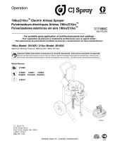
Component Identification and Function
ti2377a
K
E
H
B
A
D
J*
G
F
V
ti0866A
Fig. 1
U
N
M
PR S
W*
T
L
ti2377a
AMotor DC motor, permanent magnet, totally enclosed, fan cooled
BDrive Assembly Transfers power from DC motor to displacement pump
DDisplacement Pump Transfers fluid to be sprayed from source through spray gun
EFluid Outlet Spray gun is connected here
FPrime Valve Used to prime, drain and flush sprayer when open
GFluid Filter Final filter of fluid to spray gun
HPressure Adjusting Knob Controls fluid outlet pressure
J* Pressure Control/Display Controls motor speed to maintain fluid outlet pressure. Works with pressure ad-
justing knob. Displays pressure, gallons/liters, flush time and error codes.
KON/OFF Switch Power switch that controls main power to sprayer
L15/20A or 10/12A Switch Set to lower Amperage if circuit breaker trips when spraying (not all models)
MAirless Paint Spray Hose Grounded, conductive, nylon hose with spring guards on both ends
NSpray Gun High pressure spray gun with gun safety latch
PRAC X SwitchTip Uses high pressure fluid to clear tip clogs without removing tip from spray gun
RHandTite Tip Guard Tip guard reduces risk of injection injury
SGun Safety Latch Gun safety latch inhibits accidental triggering of spray gun
TPower Cord & Hose Rack Holds wrapped power cord and paint hose for storage
USuction Tube Transfers fluid to be sprayed from source to pump
VDrain Tube Fluid outlet used to drain and prime the sprayer
W* AutoClean valve Spray gun connection for timed back–flush of sprayer with automatic shut off
*Not available on all sprayers

4309251
General Repair Information
Pressure Relief Procedure
WARNING
INJECTION HAZARD
System pressure must be manually
relieved to prevent system from starting
or spraying accidentally. Fluid under high
pressure can be injected through skin and cause
serious injury. To reduce risk of injury from injec-
tion, splashing fluid, or moving parts, follow Pres-
sure Relief Procedure whenever you:
are instructed to relieve pressure,
stop spraying,
check or service any system equipment,
or install or clean spray tip.
1. Lock gun safety latch.
2. Turn ON/OFF switch to OFF and pressure control
knob to zero.
3. Unplug power supply cord.
4. Unlock gun safety latch. Hold metal part of gun
firmly to grounded metal pail. Trigger gun to relieve
pressure.
5. Lock gun safety latch.
6. Open pressure drain valve. Leave pressure drain
valve open until ready to spray again.
If suspected that spray tip or hose is completely
clogged, or that pressure has not been fully relieved
after following steps above, VERY SLOWLY loosen tip
guard retaining nut or hose end coupling to relieve
pressure gradually, then loosen completely. Now clear
tip or hose obstruction.
WARNING
ELECTRIC SHOCK HAZARD
MOVING PARTS HAZARD
To reduce risk of serious injury, including
electric shock, do not touch moving or
electrical parts with fingers or tools while
testing repair. Shut off and unplug spray-
er when repairing. Install all covers,
gaskets, screws and washers before
operating sprayer.
CAUTION
To reduce risk of pressure control malfunction:
Use needle nose pliers to disconnect wires. Never
pull on wire, pull on connector.
Mate wire connectors properly. Center flat blade of
insulated male connector in female connector.
Route wires carefully to avoid interference with
other connections of pressure control. Do not pinch
wires between cover and control box.
1. Keep all screws, nuts, washers, gaskets, and
electrical fittings removed during repair proce-
dures. These parts are not normally provided with
replacement assemblies.
2. Test repair after problem is corrected.
3. If sprayer does not operate properly, review
repair procedure to verify procedure was done
correctly. If necessary, see Troubleshooting Guide,
pages 5 – 8, for other possible solutions.
WARNING
HOT SURFACES HAZARD
EXPLOSION HAZARD
Motor may be very hot during operation
and could burn skin if touched.
Flammable materials spilled on hot, bare
motor could cause fire or explosion.
Have motor shroud in place during
operation to reduce risk of burns, fire or
explosion.
4. Install motor shroud before operation of spray-
er and replace if damaged. Motor shroud directs
cooling air around motor to prevent overheating. It
can also reduce risk of burns, fire or explosion; see
preceding WARNING.

5309251
Grounding
WARNING
Improper installation or alteration of grounding plug
results in risk of electric shock, fire or explosion
that could cause serious injury or death.
1. All models require a grounded outlet for power
connection. Circuit must be 50/60 Hz with an
Ampere rating equal to or greater than the sprayer.
See Fig. 2.
2. Do not alter ground prong or use adapter. Fig. 2
Grounding Plug
Grounded
Outlets
120 Vac model shown
3. 120 Vac: A 12 AWG, 3 wires with grounding prong,
300 ft (90 m) extension cord may be used.
220–240 Vac: You may use a 3-wire, 1.0 mm (12
AWG) (minimum) extension cord up to 90 m long.
Long lengths reduce sprayer performance.
Troubleshooting
Relieve pressure; page 4.
PROBLEM WHAT TO CHECK
If check is OK, go to next check
WHAT TO DO
When check is not OK refer to this column
Motor won’t operate 1. Check digital display for error codes on spray-
ers with digital displays or motor control board
inside SmartControl for blinking LED on spray-
ers without digital displays
1. If an error code (E=0X) is displayed or LED is
blinking, go to page 18 for error code diag-
nostics. If not continue.
2. Make sure digital display is connected. If noth-
ing is displayed, check power cord, power
switch and all power connections for continuity.
Check building circuit power.
2. Tighten any loose power connections. Re-
place power switch, power cord or extension
cords if damaged. Reset circuit breaker if
tripped.
3. Check pressure control knob setting. Motor will
not run if pressure control knob is at minimum
setting.
3. Increase pressure setting
4. With drain valve open and pressure control
knob set to maximum, check if there is a light
blinking next to either psi, bar, or MPa
a. If light is blinking, control board is
commanding motor to run and prob-
lem is most likely motor or motor
wiring.
b. If light is not blinking, control board,
control board wiring, potentiometer
or transducer is most likely cause.
4. Based on results of this test, investigate for
possible wiring, motor, control, transducer or
potentiometer problems in the following
steps

6309251
Troubleshooting
PROBLEM WHAT TO CHECK
If check is OK, go to next check
WHAT TO DO
When check is not OK refer to this column
Motor 1. Connections at control board and brushes 1. Repair any loose connections
2. Brushes worn. Length must be 1/2 in. minimum.
Check both sides. 2. Replace brushes. Page 9.
3. Broken or misaligned brush springs 3. Realign or replace springs
4. Brushes or springs binding in brush holder 4. Clean brush holder and align brush leads for
free movement
5. Check for armature short using an armature
tester (growler) or perform spin test. Page 9. 5. Replace motor
6. Check motor armature commutator for burn
spots or other damage 6. Remove motor and have motor shop resur-
face commutator if possible. Page 22.
Control board or wiring 1. Loose control board wiring 1. Repair any loose connections
2. Damaged control board 2. Replace control board
Control/sensor 1. Potentiometer damaged 1. Replace potentiometer
2. Pressure transducer damaged 2. Replace pressure transducer

7309251
Troubleshooting
PROBLEM WHAT TO CHECK
If check is OK, go to next check
WHAT TO DO
When check is not OK refer to this column
Low or fluctuating output 1. For worn spray tip. 1. Follow Pressure Relief Procedure Warn-
ing, then replace tip. See your separate
gun or tip manual.
2. Verify pump does not continue to stroke when
gun trigger is released. 2. Service pump. See page 23.
3. Filter clogged. 3. Relieve pressure. Check and clean filter.
4. Prime valve leaking. 4. Relieve pressure. Repair prime valve.
5. Suction hose connections. 5. Tighten any loose connections.
6. Electrical supply with volt meter.
Meter must read:
210–255 Vac for 220–240 Vac models.
85–130 Vac for 100–120 Vac models. Low volt-
ages reduce sprayer performance.
6. Reset building circuit breaker; replace
building fuse. Repair electrical outlet or try
another outlet.
7. Extension cord size and length; must be at least
12 gauge wire and no longer than 300 ft. Longer
cord lengths reduce sprayer performance.
7. Replace with a correct, grounded exten-
sion cord.
8. Low stall pressure. 8. Do either or both:
c. Turn pressure control knob fully
clockwise. Make sure pressure
control knob is properly installed
to allow full clockwise position.
d. Try a new transducer.
9. Motor armature for shorts by using an armature
tester (growler) or perform spin test. See page
9.
9. Replace motor. See page 22.
10. Paint supply. 10.Refill and reprime pump.
11. Intake strainer clogged. 11.Remove and clean, then reinstall.
12. Suction tube or fittings loose. 12.Tighten; use thread sealant or sealing tape
on threads if necessary.
13. To see if intake valve ball and piston ball are
seating properly. See page 23. 13.Remove intake valve and clean. Check
balls and seats for nicks; replace if neces-
sary, page 23. Strain paint before using to
remove particles that could clog pump.
14. Leaking around throat packing nut which may
indicate worn or damaged packings. See page
23.
14.Replace packings, page 23. Also check
piston valve seat for hardened paint or
nicks and replace if necessary. Tighten
packing nut/wet-cup.
15. Pump rod damage 15.Repair pump, page 23.
Motor runs but pump does not
stroke
1. Displacement pump pin (114) (damaged or
missing), page 23. 1. Replace pump pin if missing. Be sure re-
tainer spring (27) is fully in groove all
around connecting rod, page 23.
2. Connecting rod assembly (9) for damage, page
21. 2. Replace connecting rod assembly,
page 21.
3. Gears or drive housing, page 21. 3. Inspect drive housing assembly and gears
for damage and replace if necessary,
page 21.

8309251
Troubleshooting
TYPE OF PROBLEM WHAT TO CHECK
If check is OK, go to next check
WHAT TO DO
When check is not OK refer to this column
Building circuit breaker opens 1. Current limit exceeded 1. Switch to another circuit with less load. If
sprayer has a 15/20A or 10/12A switch,
change to lower value.
2. All electrical wiring for damaged insulation, and
all terminals for loose fit or damage. Also wires
between pressure control and motor. See page
22.
2. Repair or replace any damaged wiring or
terminals. Securely reconnect all wires.
3. For missing inspection plate gasket (see page
22), bent terminals or other metal to metal con-
tact points which could cause a short.
3. Correct faulty conditions.
4. Motor armature for shorts. Use an armature
tester (growler) or perform spin test. See page
9. Inspect windings for burns.
4. Replace motor. See page 22.
5. Motor control board (35) by performing motor
control board diagnostics on page 16. If diag-
nostics indicate, substitute with a good board.
CAUTION: Do not perform this check until mo-
tor armature is determined to be good. A bad
motor armature can burn out a good board.
5. Replace with a new pressure control board
(35). See page 16.
Display reads all 8’s Switches on back of display are set
incorrectly.
Set the four switches psi, bar, MPa and
liters/gallons to proper settings for your
sprayer. Fig. 13, page 16.
AutoClean problem Manual 309278
CAUTION
Any short in any part of the
motor power circuit will cause
the control circuit to inhibit
sprayer operation. Correctly
diagnose and repair all shorts
before checking and replac-
ing control board.

9309251
Spin Test
Setup
Electric Shock Hazard; page 4.
To check armature, motor winding and brush electrical
continuity:
1. Relieve pressure; page 4.
2. Remove drive housing; page 21.
3. Fig. 10. Remove four screws (60), pressure control
cover (49), two screws (108), control panel (67).
Fig. 3. Disconnect motor connector (F).
4. Fig. 4. Remove motor shroud (90) and inspection
covers (A).
Armature Short Circuit Test
Quickly turn motor fan by hand. If no electrical shorts,
motor coasts two or three revolutions before complete
stop. If motor does not spin freely, armature is
shorted. Replace motor; page 22.
Armature, Brushes, and Motor Wiring Open
Circuit Test (Continuity)
1. Fig. 3. Connect red and black motor leads together
with test lead. Turn motor fan by hand at about two
revolutions per second.
2. If uneven or no resistance, check for: broken brush
springs, brush leads, motor leads; loose brush
terminal screws, motor lead terminals; worn
brushes. Repair as needed; page 9.
3. If still uneven or no resistance, replace motor;
page 22.
Fig. 3
F
ti0941
Motor Brush Replacement
695 Motor Brush Removal
Replace brushes worn to less than 1/2 in. Brushes
wear differently on each side of motor, check both
sides. Brush Repair Kit 243214 is available. Spring
clip, 112766, may be purchased separately.
1. Read General Repair Information; page 4.
2. Relieve pressure; page 4.
3. Fig. 4. Remove motor shroud (90) and two inspec-
tion covers (A).
(Continued on page 10)
A
90
Fig. 4
7703B

10 309251
Motor Brush Replacement
4. Fig. 5. Push in spring clip (A) to release hook (B)
from brush holder (C). Pull out spring clip (A).
5. Fig. 5. Pull brush lead (D) out of terminal (E).
Remove brush (F).
Fig. 5
A
B
E
D
F
C
1
1
Motor lead; do not disconnect
2Minimum 0.5” (12.5 mm)
03881
3Included in Brush Repair Kit
3
2
6. Inspect commutator for excessive pitting, burning
or gouging. A black color on commutator is normal.
Have commutator resurfaced by a motor repair
shop if brushes wear too fast.
695 Motor Brush Installation
CAUTION
When installing brushes, follow all steps carefully to
avoid damaging parts.
1. Fig. 6. Install new brush (F) with lead into brush
holder (C).
2. Fig. 5. Slide brush lead (D) into terminal (E).
3. Fig. 6. Install spring clip (A). Push down to set
hook (B) into brush holder (C).
Fig. 6 03881
1
B
C
E
F
4. Repeat for other side.
5. Test brushes.
a. Remove pump (79); Displacement Pump
Replacement, page 23.
b. With sprayer OFF, turn pressure control knob
fully counterclockwise to minimum pressure.
Plug in sprayer.
c. Turn sprayer ON. Slowly increase pressure
until motor is at full speed.
CAUTION
Do not run sprayer dry for more than 30 seconds
while checking brushes to avoid damaging displace-
ment pump packings.
6. Install brush inspection covers and gaskets.
7. Break in brushes.
a. Operate sprayer 1 hour with no load.
b. Install pump (79); Displacement Pump Re-
placement, page 23.

11309251
Motor Brush Replacement
795/1095 Motor Brush Removal
NOTE: Replace brushes worn to less than 1/2 in.
Brushes wear differently on each side of motor,
check both sides. Brush Repair Kit 220853 is
available. Spring clip, 110816, may be
purchased separately.
1. Read General Repair Information; page 4.
2. Relieve pressure; page 4.
3. Fig. 4. Remove motor shield (90). Remove in-
spection covers (B) and gaskets on each side of
motor.
A
B
54
Fig. 7 7703B
4. Fig. 8. Push in 110816 spring clip (A) to release
hooks (B) from brush holder (C). Pull out spring
clip.
5. Fig. 8. Loosen terminal screw (D). Pull brush lead
(E) away, leaving motor lead (F) in place. Remove
brush (G) and spring (H).
Fig. 8
H
E
D
F
G
A
01227
BC
6. Inspect commutator for excessive pitting, burning
or gouging. A black color on commutator is normal.
Have commutator resurfaced by a qualified motor
repair shop if brushes wear too fast.
(Continued on page 12)

12 309251
Motor Brush Replacement
795/1095 Motor Brush Installation
CAUTION
When installing brushes, follow all steps carefully to
avoid damaging parts.
7. Fig. 9. Install new brush (G) with lead in long slot
(J) of brush holder (C).
8. Fig. 8. Slide brush lead (E) under washer of termi-
nal screw (D) and tighten screw. Be sure motor
lead (F) is connected at terminal screw.
9. Fig. 9.Place spring (H) on brush (G).
10. Fig. 9. Install spring clip (A). Push down to hook
short slots (K) in brush holder (C).
Fig. 9
G
K
J
C
NOTE SPRING COIL DIRECTION
A
01227
E
H
11. Repeat for other side.
12. Test brushes.
a. Remove pump connecting rod pin.
b. With sprayer OFF, turn pressure control knob
fully counterclockwise to minimum pressure.
Plug in sprayer.
c. Turn sprayer ON. Slowly increase pressure
until motor is at full speed.
CAUTION
Do not run sprayer dry for more than 30 seconds
while checking brushes to avoid damaging displace-
ment pump packings.
13. Install brush inspection covers and gaskets.
14. Break in brushes.
a. Operate sprayer 1 hour with no load.
b. Install connecting rod pin.
15. Fig. 4. Install gaskets and inspection covers (B)
on each side of motor. Install motor shield (90).

13309251
On/Off Switch Replacement
695/795 120 Vac (245000 – 245003, 245010, 245011, 245020 – 245023, 245028, 245050, 245051, 246308, 246309)
Removal
1. Relieve pressure; page 4.
2. Fig. 10. Remove four screws (60) and pressure
control cover (49). Disconnect display connector
(B) (not available on all sprayers).
3. Remove two screws (108) and control panel (67).
4. Disconnect two wires (A) from ON/OFF
switch (86).
5. Squeeze inside tabs on ON/OFF switch (86) and
remove from control panel (67).
Installation
1. Push ON/OFF switch (86) into control panel (67)
until inside tabs snap in place.
2. Connect two wires (A) to ON/OFF switch (86).
3. Install control panel (67) with two screws (108).
4. Connect display connector (B) (not available on all
sprayers). Install pressure control cover (49) with
four screws (60).
Display
Not available
on all sprayers
Wiring Diagram
ti0848A
Pressure
Transducer
Ref 68
Potentiometer
Ref 64
Red (+)
Black (–)
Yellow
Power Cord
Ref 66
On/Off
Switch
Ref 86
Black
White
70
Green
Motor
Fig. 10
49
60
86
A
67
North America
695/795 120 VAC
112
41
Black
D EBC
108
42
72
58
108
43
Ref
38 LED

14 309251
On/Off and 15/20A Switch Replacement
1095 120 Vac (245030 – 245032, 245039)
Removal
1. Relieve pressure; page 4.
2. Fig. 11. Remove four screws (60) and pressure
control cover (49). Disconnect display connector (B).
3. Remove two screws (108) and control panel (67).
4. Disconnect two wires (A1) from ON/OFF switch (86).
5. Squeeze inside tabs on ON/OFF switch (86) and
remove from control panel (67).
6. Disconnect two wires (A2) from 15/20A switch (86).
7. Squeeze inside tabs on 15/20A switch (60) and
remove from control panel (67).
Installation
1. Push 15/20A switch (60) into control panel (67) until
inside tabs snap in place.
2. Connect two wires (A2) to 15/20A switch (86).
3. Push ON/OFF switch (86) into control panel (67) until
inside tabs snap in place.
4. Connect two wires (A1) to ON/OFF switch (86).
5. Install control panel (67) with two screws (108).
6. Install display connector (B). Install pressure control
cover (49) with four screws (60).
Display
Not available
on all sprayers
ti0902A
15/20A
Switch 60
Wiring Diagram
Pressure
Transducer
Ref 68
Potentiometer
Ref 64
Red (+)
Black (–)
Yellow
Power Cord
Ref 66
On/Off
Switch
Ref 86
Black White
70
Green
North America
1095 120 VAC
Motor
Fig. 11
Black
Violet
49
60
86
A2
67
A1
60
112
41
43
D EBC
108
58
42
72
108
Ref
38 LED

15309251
On/Off Switch Replacement
695/795/1095 240 Vac (245004, 245005, 245009)
Removal
1. Relieve pressure; page 4.
2. Fig. 12. Remove four screws (60) and pressure
control cover (49). Disconnect display connector (B).
3. Remove two screws (108) and control panel (67).
4. Disconnect four wires (A) at ON/OFF switch (86).
5. Squeeze inside tabs on ON/OFF switch (86) and
remove from control panel (67).
Installation
1. Push ON/OFF switch (86) into control panel (67)
until inside tabs snap in place.
2. Connect four wires (A) to ON/OFF switch.
3. Install control panel (67) with two screws (108).
4. Install display connector (B). Install pressure control
cover (49) with four screws (60).
Display
Not available
on all sprayers
LED
Wiring Diagram
Heat from inductor coil of filter board may destroy
wire insulation that comes in contact with it. Ex-
posed wires could cause shorts and component
damage. Bundle and tie all loose wires so none lay
in contact with inductor coil of filter board.
CAUTION
Pressure
Transducer
Ref 68
Potentiometer
Ref 64
Power
Cord
Ref 66
On/Off
Switch
Ref 86
Motor
Blue
ti0897A
Red (+)
Black (–)
Yellow
Brown
Blue
Brown
Fig. 12
695/795/1095 240 VAC
42
72
108
49
60
86
A
67
112
41
D EBC
43
108
58

16 309251
Pressure Control Repair
Motor Control Board
Removal
Refer to Fig. 10, 11 or 12 depending on sprayer and
voltage.
1. Relieve pressure; page 4.
2. Remove four screws (60) and pressure control
cover (49). Disconnect display connector (B).
3. Remove two screws (108) and control panel (67).
4. Disconnect at motor control board (112):
Motor connector: two yellow, black (+) and
red (–).
Lead (D) from potentiometer.
Lead (E) from transducer.
Wires from power cord and switch
5. Remove six screws (41) and motor control
board (112).
Installation
1. Clean pad on rear of motor control board. Apply
small amount of thermal compound 073019 to pad.
2. Fig. 10. Install motor control board (112) with six
screws (41).
3. Connect to motor control board (112):
Lead (E) to transducer.
Lead (D) to potentiometer.
Motor connector: two yellow, black (+) and
red (–).
Wires to power cord and switch
4. Route loose wires so none lay in contact with
inductor coil on filter board (not 120 Vac sprayers).
See Wiring Diagram CAUTION, Fig. 11.
5. Install control panel (67) with two screws (108).
6. Install display connector (B). Install pressure
control cover (49) with four screws (60).
Digital Display Settings (Not available on
all sprayers)
The units on the digital display may be set to psi, bar,
MPa and gallons or liters.
1. Fig. 10. Remove four screws (60) and cover (49).
Disconnect display cable (B).
2. Set switches as desired, Fig. 13.
Fig. 13 MPa bar
liters
gallons
psi
SET
Shown set for
gallons and psi

17309251
Pressure Control Repair
Stored Data (Not available on all sprayers)
The SmartControl contains stored data to assist with troubleshooting and maintenance. To view this stored data on
the digital display, proceed as follows:
1. Relieve pressure; page 4.
2. Plug in sprayer.
3. Hold down display button and turn sprayer ON.
4. Release display button about 1 second after
turning on sprayer.
Sprayer model number displays (U695, U795, etc.) for
a few seconds and then data point 1 is displayed.
5. Push display button and next data point displays.
6. Turn sprayer OFF and then ON to leave stored
data mode.
Data Point Definition
1Number of hours power switch has been ON with power applied
2Number or hours motor has been running
3Number of hours sprayer has been above 500 psi with power applied
4Not used
5Last recorded Error Code E=XX. See Error Code messages on page 18.
6Control board software revision number
Note: Gallon/liter counter resets to zero at 65,000 gallons (245 700 liters)

psi
bar
MPa
18 309251
Pressure Control Repair
Digital Display Messages (Not available on all sprayers)
No display does not mean that sprayer is not pressurized. Relieve pressure before repair; page 4.
DISPLAY* SPRAYER
OPERATION
INDICATION ACTION
No Display Sprayer may be pressurized. Loss of power or display not
connected Check power source. Relieve
pressure before repair or disas-
sembly. Verify display is con-
nected.
Sprayer is pressurized. Power is applied.
(Pressure varies with tip size and pressure
control setting.)
Normal operation Spray
1. Sprayer stops. Power is applied.
2. Sprayer stops. Power is applied.
3. Sprayer continues to run
1. Exceeded pressure limit of
4500 psi. Sprayer is pres-
surized.
2. Sprayer is not pressurized
3. Pressure rise nears 4500 psi
1. Remove any filter clogs or flow
obstructions. Lock gun trigger
open if using AutoClean valve.
2. Replace transducer
3. Replace control board
Sprayer stops. Power is applied. Pressure transducer faulty,
bad connection or broken
wire.
Check transducer connections
and wire. Replace transducer or
control board, if necessary.
Sprayer stops. Power is applied. Line voltage too high Check for voltage supply problem
Sprayer stops. Power is applied. Too much motor current Check for locked rotor, pump ob-
struction, damaged drive train,
shorted wiring or motor. Repair or
replace failed parts.
Sprayer stops. Power is applied. No operation, motor over
heated or unplugged Allow sprayer to cool. Correct
cause of overheating. Verify mo-
tor is plugged into motor control
board
Sprayer stops. Power is applied. Pressure greater than
2000 psi (138 bar, 14 MPa)
while in Flush Timer Mode
Make sure spray gun is triggered
and prime valve is open when us-
ing AutoClean
Sprayer stops. Power is applied. Low line voltage Check for voltage supply problem
Power is applied. Digital display switches are
not set Set switches on back of digital
display to appropriate settings.
Fig. 13, page 16.
Sprayer may be pressurized. Pressure less than
200 psi (14 bar, 1.4 MPa) Increase pressure as needed
*Error codes also appear on control board as a blink-
ing red LED. LED is an alternate to display.
Electric shock hazard; page 4.
1. Remove four screws (60) and cover (49).
2. Turn sprayer ON. Count LED blinks. Blink count is
the same as error code (E=0X) in preceding
Digital Display Messages table.
3. Follow instructions in table.
After a fault, do following steps to restart sprayer:
1. Correct fault condition
2. Turn sprayer OFF
3. Turn sprayer ON

19309251
Pressure Control Repair
Pressure Control Transducer
Removal
Refer to Fig. 10, 11 or 12 depending on sprayer
voltage.
1. Relieve pressure; page 4.
2. Remove four screws (60) and pressure control
cover (49). Disconnect display connector (B).
3. Remove two screws (108) and control panel (67).
4. Remove upper two screws (108) and control
housing (58).
5. Disconnect lead (E) from motor control
board (112).
6. Unscrew nut holding transducer (68) in power bar
plate (56).
7. Remove transducer and o–ring (26).
8. Remove grommet (42) holding transducer lead in
cart frame (72).
9. Thread transducer lead plastic connector down
through hole in cart frame.
10. Remove grommet from transducer lead.
Installation
1. Install grommet (42) on transducer lead.
2. Thread transducer lead plastic connector up
through hole in cart frame (72) .
3. Install grommet holding transducer lead in cart
frame.
4. Install o–ring (26) and transducer (68).
5. Screw nut holding transducer in power bar plate
(56). Torque to 30–35 ft-lb.
6. Connect lead (E) to motor control board (112).
7. Install control housing (58) with upper two screws
(108).
8. Install control panel (67) with two screws (108).
9. Install display connector (B). Install pressure
control cover (49) with four screws (60).
Pressure Adjust Potentiometer
Removal
Refer to Fig. 10, 11or 12 depending on sprayer
voltage.
1. Relieve pressure; page 4.
2. Remove four screws (60) and pressure control
cover (49). Disconnect display connector (B).
3. Remove two screws (108) and control panel (67).
4. Disconnect lead (D) from motor control board
(112).
5. Remove potentiometer knob (36), sealing shaft nut
(32), shaft spacer (96) and pressure adjust poten-
tiometer (64).
Installation
1. Install pressure adjust potentiometer (64), shaft
spacer (96), sealing shaft nut (32) and potentiome-
ter knob (36).
a. Turn potentiometer fully clockwise.
b. Install knob at full clockwise position.
2. Connect lead (D) to motor control board (112).
3. Install control panel (67) with two screws (108).
4. Install display connector (B). Install pressure
control cover (49) with four screws (60).

20 309251
Drive Housing Replacement
CAUTION
Do not drop gear cluster (7) when removing drive
housing (10). Gear cluster may stay engaged in
motor front end bell or drive housing.
695 Removal
1. Relieve pressure; page 4.
2. Remove pump (79); Displacement Pump Re-
placement, page 23.
3. Fig. 15. Remove four screws (39) and remove
shroud (90).
4. Remove four screws (104) and washers (17).
5. Remove four screws (40) and front cover (100).
6. Remove two nuts (33), pail hanger (54) and spring
clip (95).
7. Remove two screws (105) and washers (17).
8. Pull drive housing (78) off of motor (75).
9. Slide connecting rod (76) out of drive housing.
695 Installation
1. Slide connecting rod (76) into drive housing.
2. Push drive housing (78) onto motor (75).
3. Install washers (17) and two screws (105).
4. Install spring clip (95), pail hanger (54) and two
nuts (33).
5. Install front cover (100) and four screws (40).
6. Install washers (17) and four screws (104).
7. Fig. 15. Install shroud (90) with four screws (39).
8. Install pump (79); Displacement Pump Replace-
ment, page 23.
695
Fig. 14 76
100
104
90
54
40
95 105
39
17
17
33
78
75
19
115
ti0767A
/