Page is loading ...

CONTENTS

User instructions
Thank you for choosing CVW's professional wireless high-
definition audio and video transmission products. Before using
this product, please read the following precautions carefully:
* Avoid using this product for long-term exposure to the sun or dust
* Be sure to use the product within the temperature and humidity range
* Do not operate the product under vibration or strong magnetic field
* Do not put conductive materials in the ventilation holes of the product
* Without the guidance of professionals of our company, please do not open
the product case by yourself
* Before power on, make sure that the input voltage of the adapter is
AC110V-220V, and the output voltage and current meet the product
specifications
* Before inserting the battery, ensure that the battery voltage meets the
product specifications
About this manual
This manual details the product specifications and interface
descriptions, instructions for use, precautions, and
troubleshooting. Please read the instructions carefully before
using the product. If you have any questions or difficulties in
using this product, please contact our company or distributor in
time.
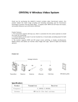
Product Brief
This product is a wireless video transmission system based on
the 5GHz frequency band, with a maximum video resolution of
1080P60Hz, which can be widely used in commercial live
broadcast, event live broadcast, film and television shooting,
campus radio and other fields.
System connection diagram
This product includes a transmitter and a receiver. The
transmitter supports 1 HDMI input and SDI input and loop-out.
The receiver supports 1 HDMI and 2 SDI output at the same time.
The following is a schematic diagram of the application
connection of this product.

Product Highlights
High-quality low-latency video
Support HD-SDI & 3G-SDI input and output, support HDMI full HD input
and output, the highest resolution is 1080P60Hz. Using H.264 codec
technology, the image is high-definition, and the delay is as low as 70ms
Product packaging details
After unpacking, please check the packing list details, if there are missing
parts, please contact the dealer. The parts involved in each model are subject
to the following packing list.
Beam-Forming
Combining 2x2 MIMO and Beam-Forming (beam forming) technology makes
the wireless beam more concentrated and more directional in the direction
of transmission to reception, higher signal-to-noise ratio, and a longer
transmission distance
Stronger anti-interference ability
Point-to-point mode and pull flow mode
Support two working modes of point-to-point and RTSP pull flow and can
be switched. In the point-to-point mode, the product supports one send and
one receive and the video output interface is HDMI and SDI. In the RTSP
pull-stream mode, the product supports one send, one receive, and one
send, multiple receive. There are more options for different applications.
01
02

A
B
C
D
E
K
USB
H
I
J
Product
interfaceintroduction Transmitter 7103 interface description
TX
F
G
Antenna interface
Power button
OLED display
CH button
MODE button
HDMI input
DC IN
USB interface
SDI loop output
SDI input
NP
-F battery interface
A
B
C
D
E
F
G
H
I
J
K
SWIFT 800 PRO
03
04

Receiver interface introduction Receiver 3103 interface description:
RX:3103
A
B
C
D
E
F
G
USB
H
K
I
J
05 06
Antenna interface power button
OLED display
CH button
MODE button
HDMI output
DC IN
USB interface
SDI output
SDI output
NP
-F battery interface
A
B
C
D
E
F
G
H
I
J
K
说明
序号
SWIFT 800 PRO

RF signal
VIDEO
Video signal
CH 1
Work channel
OLEDDisplay
instructions
TX:7103
Transmission distance
Factors affecting distance
The installation height of the transmitter and the receiver: a higher installation height will avoid being
blocked by objects and humans, increasing the distance
Wireless transmission code rate, the larger the code rate, the shorter the
transmission distance, the recommended single channel code rate is 15Mbps
Blocking of objects such as metals, walls, or human bodies will cause the wireless
signal strength to be greatly attenuated, resulting in a reduction in transmission
distance
Whether there is interference
Whether the antenna placement angle is in an ideal state
RX:3103
RF signal
VIDEO
Video signal
CH 1
Work channel
05
06

Product installation
instructions
Transmitter installation instructions
1. Please install the antenna to the antenna
interface of the transmitter as shown in the figure.
To obtain the best wireless transmission distance,
the antenna
The following picture is placed (90 ° angle between
2 antennas)
(as the picture shows)
3. Fix the transmitter to the camera head or handle through the nut hole on the
bottom of the fuselage (as shown in the figure) Warning: When the device is not
in use, the battery needs to be removed.
Receiver installation instructions
1,Please install the antenna to the antenna interface of the receiver
according to the figure.
1. Install the transmitter battery (as shown)
90
90
SWIFT 800 PRO
SWIFT 800 PRO
07
08

Product operation
1. Product connection
Use HDMI or SDI cable to connect the transmitter to the camera \ SLR camera
2. Use HDMI or SDI cable to connect the receiver and monitor, or other receiver
products。
SDI
HDMI
SDI
HDMI
SWIFT 800 PRO
09
10

DC
Power supply and start
The transmitter uses any of the following power supply methods,
long press the power button 3S to start the transmitter
a) Install the NP-F battery in the NP-F battery slot on the back of the
transmitter
1. The receiver uses any of the following methods to supply power. Press
and hold the power button 3S to start the receiver
2.
Use the included DC power adapter to power the product
a) D-type to DC cable is required to use V-bucket batteries
to power the product
D-type- DC
b) Use V button battery to power the product (need to use D-type to DC cable)
D-type-DC
09
10

Switch channel
Tap the CH button of the transmitter or receiver to switch channels. Both the
OLED screens of the receiver and transmitter will display the channel CH
number after switching.
Code operation
This function needs to be operated on the transmitter and receiver:
This function needs to be operated on the transmitter and receiver
Press and hold the CH button for 3
seconds and release the button
Receiver: Press and hold the CH button for 3 seconds, then release
the button, the OLED screen displays WPS characters, the receiver
enters the code matching mod
Press and hold the CH button for 3
seconds and release the button
Working mode and switching
1. Point-to-point mode
In the point-to-point mode, the video source is given to the
transmitter through HDMI or SDI, and the receiver will output the
received signal to the video channel through HDMI and SDI interfaces
to monitors, switch stations and other products.
2. Pull flow mode
In pull-stream mode, the video source can be simultaneously
transmitted to the receiver, mobile phone, iPad, etc. products that are
in the same network as the transmitter via WiFi networking through
the HDMI or SDI interface of the transmitter: the receiver will receive
the The signal is output to the monitor through the HDMI and SDI
interfaces; the mobile phone, iPad, etc. will directly display the
received video signal
on the screen.
Work mode switch
1. Switching between the two operating modes requires operation on
the transmitter and receiver (the transmitter and receiver need to
work in the same mode for the transmitter and receiver to be in a
normal connection).
2. The product's factory mode is point-to-point mode.
3. Press and hold the MODE button of the transmitter and receiver for
3 seconds to switch the mode. When switching from point-to-point
mode to pull-current mode, the word "RTSP" will be displayed on the
OLED display; when switching from pull-current mode to point-to-
point mode "RTSP" will disappear on the OLED display.
Pull flow mode operation
Instructions for using the mobile APP
09
10

Firmware upgrade Product specification
1. The operation of the wireless software upgrade of the transmitter and receiver is
the same.。
2. Download the firmware to be upgraded to a storage device such as a
USB flash drive, and connect the USB flash drive to the USB interface
of the product. After the product is powered on, the product will
automatically upgrade after reading the firmware upgrade, and the upgrade
will be completed after the product is restarted. At this time, you can
unplug the U disk (from Xie Zongna learned that you do not need to use
U disk to connect to product upgrades in the future, only need APP to do
software upgrade, one-click download and upgrade; if U disk upgrade is
required, please describe in detail, For example, what is the status of
the lights before and after the upgrade?)
project TX:
710
3
RX: 3103
Operating frequency
range
5.10~5.90 (GHz)
Video format 1080p60/59.94 、1080p50、1080p30/29.97、1080p25、1080p24/23.98、
1080psf24/23.98(SDI)
1080i60/59.94、1080i50 、
720p60/59.94 、720p50(SDI-3GA&3GB)
audio format
PCM
HDMI protocol
HDMI 1.3
;
HDMI 1.4
SDI specification
3G-SDI
、
HD-SDI
、
SD-SDI
Transmission delay
70ms
Video compression
format
H.264
Transmission distance
250m (2dbi Antenna, straight line without obstruction)
Antenna method
2T2R External
interface DC-IN、SDI-IN、SDI-LOOP OUT、
HDMI-IN、Type-C USB、
NP-F970、
SMA *2
DC-IN、SDI-OUT*2、HDMI-OUT、
Type-C USB、NP-F970、SMA *2
button
1.POWER
;
2.CH
;
3. MODE
Working power 1.DC(7V~36V)
2. Lithium battery (SONY NP-F970 or compatible series)
Product Size
110*70*21 (Unit: mm, without battery buckle plate)
Operating temperature -10~45°C
Storage temperature
-40
℃
- 80
℃
certified product
FCC
、
CE
Installation interface
1/4 inch nut at the bottom
09
10

Precautions
Installation height and separation distance
1. This product has a transmission distance of 250 meters under the same viewing
distance, unobstructed, best installation method, and the same antenna polarity, and
different code streams correspond to different distances; In the case of different
polarities, the distance will be shortened
2. To avoid human obstruction, the transmitter is 1.5-2 meters above the
ground and the receiver is 2 meters above the ground
3. When multiple sets of products work at the same time, please ensure that the
distance between the transmitters is at least 1 meter, and the working frequency
points between the products are staggered
4. When the receiver and other wireless products are placed and working, please
separate the receiver from other wireless products by more than 2 meters.
Frequency setting
1. When using a single set of products, it is recommended to set the frequency
point to CH5-CH9, because in many Wi-Fi coverage scenarios, the signal is
concentrated at low and high frequencies, and the spectrum occupancy rate
of the intermediate frequency is low
2. When two sets of the same product are used at the same time, the interval
between each set of products is more than 1 meter, and the frequency point is
set at more than 2 frequency points. For example, the first set of products is set
at CH5, and the other set of products is set at CH7 or CH8 or CH9. , Which is set
more than 2 frequency points apart
3. When multiple sets of the same product are used at the same time, each set of
products is separated by more than 1 meter, and the frequency point is set at 2
frequency points, that is, the first set of products is set at CH5, the second set is set
at CH7, and the third set is set On CH9, set up more than 2 frequency points
Environmental factors affecting wireless transmission
The following environment will affect the quality of wireless transmission, resulting in
confusing image sound
(Picture pause, noise, noise, etc.):
a) Walls, large metal plates, and appliances will affect the wireless transmission, try
to avoid use in these environments;
b) When used under crowded conditions, the transmitter can be raised
as high as possible to more than 1.5--2 meters; the receiver should
be raised as high as possible to more than 2-3 meters
c) If there is a wireless product using 5GHZ nearby, it may also cause
interference to wireless transmission, which can be solved by switching the
frequency point. It is recommended to switch the product frequency point to
CH5-CH9 in case of interference。
d) Do not install the transmitter and receiver in a metal shelf, which will affect the
wireless transmission. If it is unavoidable, you need to consider leading the
antenna out
Cable connection
a)
Try to avoid plugging and unplugging the HDMI / SDI cable of the transmitter and
receiver during normal use
b)
Please try to connect the transmitter and the video source through HDMI / SDI,
and connect the receiver and the monitor before starting the transmitter and
the receiver
Product and antenna installation
a) When installing with the double-head screw that comes with this product,
please use the tightening screw to lock the product, do not hold the
product to rotate and tighten, to prevent the screw from being removed
from the product
b) When installing the transmitter and receiver, be sure to install
the antenna first, and then turn on the power, otherwise it may
cause damage to the product
09
10

c) The antenna is in the right direction and the transmission effect is the best
d) Before powering on, please make sure that the product antenna has been
installed completely
Battery life
Take SONY NPF-970 battery as an example, SONY NPF-970 battery 58WH,
transmitter working life 5-6 hours
Note: The above values are affected by the specific use environment and products
Trouble shooting
1. The transmitter and receiver cannot establish a connection
a) If the transmitter and receiver are connected to the antenna, the distance between
the transmitter and receiver is at least 1 meter
b) The transmitting frame is set to the camera head or handle at a height of 1.5-2
meters from the ground. The cameraman's body should try not to block the
antenna's cylindrical surface. The receiving frame is set to be more than 2
meters from the ground and the antenna is positive Yes, the transmission effect
is the best
2. Mosaic and stutter appear on the screen
Please confirm that the following conditions have been fulfilled:
a) When multiple sets of products work at the same time, please ensure that the
distance between the products is at least 2 meters
b) The transmitter is mounted to the camera head or handle at a height of 1.5-2
meters from the ground. The cameraman's body should try not to block the cylinder
of the antenna. The receiving rack is set to be more than 2 meters from the ground,
and the antenna is fan-shaped
c) The frequency is set between CH5-CH9
d) If multiple sets of products are used at the same time, please separate the multiple
sets of products by more than 2 meters
e) If there is a wireless guided call system on site, please separate the
guided call host and the image transmission receiver by more than 2
meters
3. The output shows a black screen
09
10

a)
Please confirm whether there is OSD "connecting to transmitter" or "link
connected to transmitter, please check video source" on the black screen. If the
OSD displays "connecting to transmitter", please check according to the
transmitter and receiver cannot establish a connection "; if the OSD displays"
link connected to transmitter, please check video source ", please check the
video source or connection of the transmitter Is there a problem with the SDI /
HDMI cable
b)
If the receiver output black screen after switching the video source resolution,
there is no video source output, please unplug the HDMI / SDI cable of the
transmitter or receiver. If the HDMI / SDI cable cannot be recovered by
plugging and unplugging, please power off and restart the transmitter and
receiver
4. The receiver is connected to the guide station or monitor
without image output
Please confirm whether the signal strength grid and VIDEO characters
are displayed on the OLED screens of the transmitter and receiver. If
there is no signal strength grid, it means that the network is not
connected. Please check according to "The transmitter and receiver
cannot be connected"; , If there is no VIDEO character, please check
the video source and the connected SDI / HDMI cable; if the
transmitter and receiver have both signal strength grid and VIDEO
characters, the monitor is blank or not displayed, please check the
receiver and monitor dock SDI / HDMI cable, change the resolution of
the camera to 1080i 50 or 720P 50 for verification; at the same time,
you can also connect the SDI / HDMI cable of the receiver to other
monitors
verification
5. A green splash screen appears in the output image
The transmitter or receiver HDMI interface is not plugged in firmly, or the camera HDMI
interface is not plugged in firmly, pluggable HDMI / SDI cable or replace HDMI / SDI cable.
09
10

FCC Warning
This device complies with part 15 of the FCC rules. Operation is subject to the following two conditions: (1) this device may not cause harmful interference,
and (2) this device must accept any inte rference received, including interference that may cause undesired operation.
Changes or modifications not expressly approved by the party responsible for compliance could void the user's authority to operate the equipment.
NOTE: This equipment has been tested and found to comply with the limits for a Class B digital device, pursuant to part 15 of the FCC Rules. These limits are
designed to provide reasonable protection against harmful interference in a residential installation. This equipment generates uses and can radiate radio
frequency energy and, if not installed and used in accordance with the instructions, may cause harmful interference to radio communications. However, there
is no guarantee that interference will not occur in a particular installation. If this equipment does cause harmful interferenceto radio or television reception,
which can be determined by turning the equipment off and on, the user is encouraged to try to correct the interference by one or more of the following
measures:
• Reorient or relocate the receiving antenna.
• Increase the separation between the equipment and receiver.
• Connect the equipment into an outlet on a circuit different from that to which the receiver is connected.
• Consult the dealer or an experienced radio/TV technician for help.
Radiation Exposure Statement
This equipment complies with FCC radiation exposure limits set forth for an uncontrolled environment. This equipment should be installed and operated with
minimum distance 20cm between the radiator and your body.
09
10
/