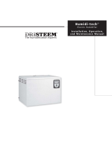
RMB35

GeneralAire RMB35 User manual

  • Hello! I've reviewed the GeneralAire RMB35 Room Steam Kit user manual. This document provides detailed instructions for installation, operation, and maintenance of the steam kit, which is designed for use with the GeneralAire 5500 Steam Humidifier. The manual includes information on components, electrical connections, and hose routing. I'm ready to answer your questions about the device described in the manual including it's features or installation process.
  • What is included in the Room Steam Kit?
    Where should the room steam kit be located?
    How long does the blower continue to run after the demand for humidification ends?
1 | P a g e
Installation & User Manual
1.1 Room Steam Kit RMB35; GFI #7660 / CGF #RMB35R (230VAC 1)
For use ONLY with GeneralAire® 5500
1.2 Components Included in the Room Steam Kit
The Room Steam Kit Includes:
Housing (includes the fan and distributor);
Grille (includes the small intake filter);
9’ of 3/8” ID condensate hose;
3/8” x 3/8” barbed hose fitting;
Small hose clamp.
Part No. 5500-33 Rev B.
2 | P a g e
1.3 Operation
When a call for humidity is received, the 5500 Steam Humidifier control module will supply power to the steam cylinder
and the room steam kit blower, which will run and distribute steam into the room. The room steam kit grill is designed to
blow steam outward and slightly down to avoid condensation on the ceiling. A cleanable filter is located behind the air
intake grill to protect the motor from large particles. When the demand for humidification ends, power to the steam
cylinder is stopped, while the room steam kit blower continues to run for 30 seconds to distribute any remaining steam.
1.4 Choosing a Location
Locate the room steam kit on a wall in the largest room / space to be humidified, allowing humidity to migrate from the
largest space to other smaller spaces throughout the home. Do not install the room steam kit in small, confined spaces
such as closets, bathrooms, or hallways. The room steam kit must be mounted above the 5500 Steam Humidifier since
the room steam kit will create condensate that must drain back to the humidifier by gravity. Room steam kit wall
blowers may only be installed in a vertical wall distributing steam horizontally. (See Figure 10.a.)
NOTES:
1. The room steam kit must be installed in the wall and connected to the humidifier with the steam hose supplied.
2. The room steam kit must be mounted at least 15 inches above the humidifier to achieve 30-degree minimum slope
and avoid condensation / gurgling. (See Figure 10.a.)
3. Avoid undrained pockets and traps in the hoses. Condensate will accumulate in low areas and prevent steam
movement. The steam hose must not have sharp bends or twists.
4. The dimensions in Figure 10.b. are minimum distances to prevent the humidified air from coming in contact with
people, electrical equipment, ceilings and cold surfaces before the steam has been completely absorbed.
Choose the location with care as the steam is hot and can cause burns.
5. The maximum total length of rubber steam hose is 12 feet (3.7m). The maximum total length of insulated copper
tubing may be up to 20 feet (6m). The maximum combined allowed length of steam hose and insulated copper
tubing is 32 feet (9.75m). In all cases, minimize sharp bends and elbows. Use 2 - 45° elbows instead of 90°
elbows. Hose inner diameter 7/8” (22 mm); outer diameter 1 ¼” (30 mm). Additional steam hose is available: GFI
#7513 / CGF #GF-20-2.
1.5 Wall Opening
The room steam kit housing will fit in a standard 2 x 6 wall with ½” drywall. If installing in a 2 x 4 wall then the rear
drywall must also be removed and the housing will protrude out the back of the wall. Figure 10.d shows the wall
opening dimensions for the room steam kit housing.
Figure 10.b.
Figure 10.a.
24
60”
6”
3 | P a g e
NOTES:
1. The room steam kit housing has flanges on the front that must be mounted on the outside face of the drywall.
2. When installing in new construction, use a piece of return air angle to mark where the room steam kit will go to
prevent the drywall from being installed over the location for the room steam kit housing.
1.6 Housing Knockouts
Determine if the steam will be entering the housing from the back or bottom. Remove the knockouts for the steam
hose, condensate hose, and electrical connections. (See Figure 10.d.).
.
Figure 10.d.
Figure 10.c.
12-1/8”
WIDE
8-1/8”
HIGH
ELECTRICAL
KNOCKOUT
STEAM HOSE KNOCKOUT
TERMINAL
BLOCK
(Front View; Without Gril)
5-11/16
(Bottom View)
4 | P a g e
1.7 Installation
Insert the room steam kit housing into the wall and bend the four securing tabs around the back of the drywall. Level
the room steam kit, then secure to the wall using predrilled holes located on the four one-inch flanges. Use #8 drywall
screws (four required) to penetrate the drywall and pass through the slot in the securing tab behind the drywall (See
Figure 10.e and 10.f). An alternate installation method is to frame out the opening of the RMB to the dimensions
shown in Figure 10.d.
The four one-inch flanges on the face of the Room Steam Kit unit must be on the outside of the drywall.
Failure to locate the flanges on the outside face of the drywall may result in water leakage and household
damage.
Figure 10.e.
Figure 10.f.
Section through Room Steam Kit flange and securing tab
SECURING TABS
BENT INTO POSITION TO
ATTACH TO DRYWALL.
#8 SCREW
RUNS THROUGH FRONT FLANGE
AND INTO SLOT IN SECURING TAB
FRONT of Room Steam Kit
BACK of Room Steam Kit
5 | P a g e
1.8 Electrical Connections
The room steam kit fan is fitted with a power supply terminal block (Figure 10.g.) with two terminals and a ground wire
connector on the housing. The power wire should be 16 gauge or larger shielded cable with ground. Power wiring
should be run through the electrical knockout in the RMB and be secured with the supplied cable clamp.
The power for the RMB Kit will be supplied by a 115Vac or 230Vac external power source. The EXT FAN low voltage
terminals “NO” / “C” (dry contacts) will be used to control the function of the Room Steam Kit blower. Connect the wiring
for the Room Steam Kit as shown in Figure 10.g.
1. Power for the Room Steam Kit is from the terminals on the BACK of the control module.
2. Electrical conmnections must be performed by qualified personnel in compliance with local codes.
Figure 10.g.
COMPONENT KEY
EVF = FILL VALVE
DP = DRAIN PUMP
DT = DRAIN TEMPERING VALVE
HL = HIGH LEVEL SENSOR
REMOTE MOUNT
BLOWER (RMB)
FOR OPTIONAL
INSTALALTION
230V ONLY
*SEE NOTE
230V
230V
230V
115V
(L1)
VOLTAGE SWITCH
(L2)
230V
ELECTRODE CONNECTION
E1
E2
L1(N) L2(F)
*NOTE: CYLINDER E1-E2 ELECTRODES POWERED
BY INCOMING VOLTAGE (115V OR 230V)
6 | P a g e
1.9 Hose Routing and Connections
Connect the steam hose to the stainless elbow fitting located at the bottom of the manifold and secure with the hose
clamp provided. Do not force the steam hose onto the stainless fitting - apply some water to the inside of the hose and
ease the hose onto the fitting. Connect the condensate hose to the molded barbed fitting on the right (See Figure
10.h). The condensate hose needs to be trapped immediately under the blower housing or directly above the steam
humidifier using a 6” loop in the condensate hose. See the 5500 Steam Humidifier Installation Manual; section 3.4.4.
The 3/8” x 3/8” barbed hose fitting enables the condensate hose to connect to the fill cup. Insert one end of the fitting
into the condensate hose (Figure 10.i.), route the hose into the unit through the hole in the enclosure, and then insert
the other end of the fitting into the hole on the top of the fill cup (Figure 10.j.).
.
The standard steam unit comes with 6 feet (1.8m) of steam hose. The Room Steam Kit comes
with 9 feet (2.7m) of 3/8” ID hose. The maximum total length of rubber steam hose is 12 feet (3.7m). The
maximum total length of insulated copper tubing may be up to 20 feet (6.1m). The maximum combined allowed
length of steam hose and insulated copper tubing is 32 feet (9.75m). In all cases, minimize sharp bends and
elbows. Use 2 - 45° elbows instead of 90° elbows. Hose inner diameter 7/8” (22 mm); outer diameter 1 ¼” (30
mm). Additional steam hose is available GFI #7513 / CGF #GF-20-2.
1.10 Room Steam Kit Grille Installation
Attach the air filter to the grill. Install the grill over the housing face and use the provided screws and pre-drilled holes
to secure the grill to the RMB housing. The steam manifold will extend out past the face of the grill. The grill may be
painted to match decorations in the home.
Use only the grill that was provided with the room steam kit. Any alterations or changes to the
grill may result in water leakage and damage to the home.
1.11 Room Steam Kit Grille Maintenance
The air filter should be vacuumed or rinsed with water at least once per year. More frequent cleaning may be necessary
depending on home conditions. Neglecting the air filter (cleaning and/or replacement) will seriously affect the operation
of the room steam unit.
NOTE: For new construction, the air filter must be cleaned as needed during construction and again when construction
is complete.
1.12 Room Steam Kit Grille Start-up
The RMB blower will operate when the humidifier has a demand for humidity. Operation will continue for 30 seconds
after the demand is complete.
Figure 10.h.
Figure 10.j.
Figure 10.i.
STEAM INLET
CONNECTION
CONDENSATE HOSE
CONNECTION
7 | P a g e
1.13 Technical Specifications
Description
Value or range
Steam output (lb/hr)
0-12
Storage temperature (ºC)
-10 to 70
Rated power (W)
24
Rated air flow-rate (cfm)
71
Noise level (open field, at maximum speed, one metre from the front panel) (dB)
30
1.14 Table of Spare Parts
GFI #
Part Number
Description
7660
RMB35
Room Steam Kit (230V)
7535
35-02
Room Blower Assembly 230V for RMB35
7513
20-2
Steam Hose 7/8” ID
7512
20-3
Condensate Hose 3/8” ID
7559
35-10
Hardware Kit (for RMB15/RMB35)
7536
35-20
Internal Steam Distributor Manifold
7528
35-26
Front Grill (for RMB15/RMB35 - includes filter, labels)
7647
P-241
Steam Hose Clamp #16
7648
P-242
Condensate Hose Clamp #6
43800 GRAND RIVER AVENUE 400 MIDWEST ROAD
NOVI, MI. 48375 TORONTO, ON M1P3A9
(866) 476-5101 (888) 216-9184
www.generalfilters.com www.cgfproducts.com
8 | P a g e
About General Filters
Founded in 1937, General Filters, Inc. is a leading manufacturer of premium residential whole-house,
humidifiers, dehumidifiers, air cleaners, UV air purifiers, heat / energy ventilators, and fuel oil filters; a
complete line of dependable, high quality IAQ and heating solutions for today’s energy-efficient homes.
GeneralAire® indoor air quality products allow you to Breathe Healthier in the comfort of your own
home. Located in Novi, MI General Filters products (under the IAQ brand names GeneralAire® and Second
Wind™; and oil brand names General, Unifilter®, and Gar-Ber) are made in the USA!
We spend up to 90% of our time indoors, while experts say indoor air can be more polluted than outdoor air.
How Can Indoor Air Quality Products Help?
Air Cleaners
Quality air cleaners are very effective in removing airborne particulates; particulates that can trigger allergy
and asthma symptoms and cause long-term adverse health effects. Air cleaner filters are MERV rated
(Minimum Efficiency Reporting Value) with ratings from 1 to 16. The higher the MERV rating, the more
effective the filter is at removing smaller and more harmful particulates from the air.
Humidifiers
Dry air can have adverse effects not only on your health but your home and its contents. Dry air causes
cracks in wood floors, furniture, trim and musical instruments. Dry air can cause static electricity that can
damage expensive electronics. Dry sinuses can leave you susceptible to colds and flu. Allergy and asthma
triggers may increase. Dry air can increase heating bills by causing gaps in doors and windows that allow
cold air inside. Humidifiers add moisture levels in your home so that you and your family feel better, while
also protecting your home and contents.
Dehumidifiers
Like air that is too dry, air that's too moist can also be detrimental. Too much moisture can increase
incidents of mold, mildew and bacteria, also increasing allergy and asthma triggers. Your clothing and
bedding may feel moist and uncomfortable. Breathing may become more difficult. High humidity attracts
pests drawn to moisture. Whether you live in a humid climate or it’s simply that time of year, a dehumidifier
reduces excess moisture for greater comfort and healthier indoor air quality.
UV Air Purifiers
Bring the sun’s purification benefits indoors with the installation of a Second Wind™ UV Air Purifier. Ultra
violet light disables and destroys viruses and airborne pathogens, while eliminating molds and spores from
forming within the home’s HVAC system.
/