Page is loading ...

Power source: 220-240VAC
Power frequency: 50Hz
Rated load: 2000W Max.tungsten
500W Max.fluorescent & LED
Time setting: impulse,10sec~20min
(adjust manually/ by infrared remote control)
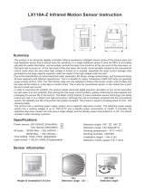
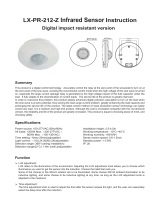
Detection range: 2-8m Max. (radii.)(ceiling installation)
(adjust manually/ by infrared remote control)
Detection angle: 360º (ceiling installation)
LX-PR-127 Infrared Sensor Instruction
Summary
Specifications
Light-control: <10LUX~2000LUX
(adjust manually/ by infrared remote control)
Installation height: 2~4m
Protection level: IP55
Power consumption: working 0.5W
Sense motion speed: 0.6~1.5m/s
Working temperature: -10°C~+40°C
Working humidity: <93%RH
IP 55
IP 55
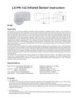
39.4mm
64.2mm
Ø120mm
Ø120mm
43mm
68mm
Ø4.2mm
41mm
60mm
70mm
85mm
80mm
61mm
Ø4.2mm
Ø59.5mm
80mm
85.5mm
70mm
58.6mm
Function
Can identify day and night: the light control can be adjusted freely when it works. It can work in the daytime
and at night when it is adjusted on the “sun” position (max); but it can only work in the light control less than
10lux when it is adjusted on the “moon” position (min). As for the adjustment pattern, please refer to the
testing pattern.
Light-control potentiometer (LUX): clockwise the knob to increase its value; anti-clockwise the knob to
decrease its value.
Working time delay adjustable: the length of the delay time can set according to the needs of users by
oneself, can be set up in 10 seconds (counterclockwise spin after the callback) to the 20 minutes (exactly)
clockwise rotation range, to detect the mobile signal before the end of the this time will be to timing, it is
recommended to adjust the detection range or walk test to choose the shortest time.When time knob to
adjust to the smallest ( ), to "impulse " mode.
The product is a PIR sensor switch, utilizes the infrared energy from human as control-signal source and
determine the light to need to work or not, and control the light on and off automatically .When one enters the
detection filed and trigger the sensor to work ,the light turns on; when one leaves the detection filed and the
setting time reaches, the light will turn off.It can detect the ambient light illumination automatically and set and
adjust the value according to the fact need. Such as, the light will turn on and works when the ambient light
illumination is under setting value. once it exceeds the setting value, the light will stop working.The light will be
on until the time-delay comes when the sensor is triggered. Once detected the constant signal, the time will be
overlaid and the light will be on constantly.It can be installed in indoor, corridor and public-building.

Setting manner :potentiometer
It may take times to adjust values before they satisfy your need.
Sensor information
Sensing angle adjustment range Sensing distance adjustment rangeHeight of installation2~4m
Time delay can be added continually: when it received the second induction signal after the first it will
compute time once more on the rest of the first time delay basic.(Set time)
Products induction distance is adjustable.
Products with the remote control.
Product installation support embedded installation and normal installation with base cover.
2~4
m
360°
Max:8m
Max:2m Max:2m
Max:8m
TIM E
SEN S
LUX
+
+
-
TIME
SENS
LUX
+
+
-
<10-2000LUX
LUX
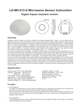
When the counterclockwise rotation is at the end, the working illuminance is about 10
LUX, and the working illuminance is about 2000 LUX when rotated clockwise. When
walking a test during the day or adjusting the detection area, this knob must be turned
fully counterclockwise.
(1Light-control setting
Clockwise rotation increases, counterclockwise rotation decreases. When adjusting to
the maximum, the delay time is 20 minutes. When it is adjusted to the minimum ( ),
it is a flash jump mode. In the flash jump mode, if you want to adjust to the short time
mode, adjust the knob clockwise one time, and the LED indicator flashes three times.
It is recommended to select the shortest time when adjusting the detection range or
walking test.
Note: After the lamp is off, wait for approximately 3 seconds before it can sense again.
The light will only light when a signal is detected after this time has elapsed.
10sec-20min
TIME
+
(2)Time setting

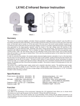
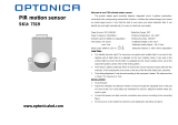
Connection-wire diagram
(1) Turn off the power before installation;
(2) Open the top cover with a screwdriver and remove it.
Unscrew the screws holding the sensor body and
bottom cover;
(3) Install the bottom cover (eg 1) in the selected position;
(4) Connect the power supply and load to the sensor
terminal according to the wiring diagram;
(5) The sensor body is fixed on the bottom cover (eg 2);
(6) Fasten the top cover to the sensor (eg 3) and
complete the installation.
Installation instruction
ATTENTION: When use this product, please adjust the sensitivity to an appropriate position
you need, please do not adjust the sensitivity to maximum, to avoid the product does not
work normally caused by wrong motion.Because the sensitivity is too high easily detect the
wrong motion by wind blowing leaves & curtains, small animals, and the wrong motion by
interference of power grid & electrical equipment. All those lead the product does not work
normally ! When the product does not work normally, please try to lower the sensitivity
appropriately, and then test it.
When the knob is turned clockwise, the detection distance increases, and the detection
distance decreases when the knob is turned counterclockwise. When the
counterclockwise rotation is complete, the detection distance is the smallest (a radius of
nearly 2 meters), and the detection distance is the longest when rotated clockwise (a
radius of nearly 8 meters).
Correct use of delay adjustment: It is used to adjust the delay time from sensor lighting to
automatic light extinguishing after human body motion is detected. Users can adjust
according to actual needs. Since infrared sensing products have continuous sensing
function, in short, the sensor will sense any time before the end of the delay time, the system
will re-time, as long as people are active in the detection range, the light will not die.
Therefore, users are advised to reduce the delay time as much as possible to achieve energy
savings.
(1)Detection range setting(sensitivity)
SENS
+
-
2-8m
Installation according to the wiring
diagram provided (right)
R-side function:manually triggering
the induction function.
L L N N R
L
L
N N R
Input
Load
R
220V~
①
②
③
①
②
③
Overall installation Embedded installation

The load don’t work:
a. Please check the power and load connect is correct.
b. Check if the load is good.
c. Check if the show lamp accelerates its speed after detecting.
d. Check if the working light corresponds to the light-control.
The sensitivity is poor:
a. Please check if there is hinder in front of the detection window to effect receiving the signals.
b. Please check if the ambient temperature is too high.
c. Please check if the signals source is in the detection fields.
d. Please check if the installation height corresponds to the height showed in the instruction.
e. Please check if the moving orientation is correct.
The sensor can’t shut the load automatically:
a. Check if there are continual signals in the detection fields.
b. Check if the time setting is set to the longest.
c. Check if the power corresponds to the instruction.
d. Check if the temperature change obviously nears the sensor, such as air condition or central heating etc.
Avoid installing it near air temperature alteration zones such as air condition, central heating, etc.
Considering your safety, please don’t open the cover when you find the hitch after installation.
If there is difference between product and instruction, please refer to product mainly.
Some problem and solved way
Should be installed by electrician or experienced man.
Avoid installing it on the unrest objects.
There shouldn’t be hindrance and moving object in front of the detection window effecting detection.
Note
● Please confirm with prefessional installation.
● For safety purposes, please cut off power before installation and removal operations.
● Any losses caused by improper operation,the manufacturer does not undertake any
responsibility.
Warning!
We are committed to promoting the product quality and reliability, however, all the electronic
components have certain probabilities to become ineffective, which will cause some
troubles.When designing, we have paid attention to redundant designs and adopted safety
quota to avoid any troubles.
This instruction, without our permission, should not be copied for any other purposes.
/