Page is loading ...


Table of Content
1. INTRODUCTION................................................................................................................ 2
1.1 PACKAGE CONTENT ................................................................................................................................................2
1.2 KEY FEATURES .......................................................................................................................................................2
1.3 PHYSICAL DESCRIPTION..........................................................................................................................................3
2. INSTALLATION ................................................................................................................. 5
2.1 RACK MOUNTING ....................................................................................................................................................5
2.2 POWER SUPPLY ......................................................................................................................................................5
2.3 CONVERTER MODULE..............................................................................................................................................5
2.4 MANAGEMENT BOARD MODULE...............................................................................................................................5
3. WEB-BASED USER INTERFACE..................................................................................... 7
3.1 SETTING UP CONNECTION .......................................................................................................................................7
3.2 MAIN PAGE .............................................................................................................................................................7
3.3 REAR PANEL INFORMATION....................................................................................................................................11
3.4 MANAGER SETTINGS.............................................................................................................................................11
3.5 CONFIGURATION ...................................................................................................................................................13
3.6 TRAP....................................................................................................................................................................14
4. TEXT-BASED USER INTERFACE.................................................................................. 16
4.1 SETUP THE CONNECTION ......................................................................................................................................16
4.2 TOP LEVEL MENU..................................................................................................................................................17
4.3 IP ADDRESS SETTING............................................................................................................................................18
4.4 SYSTEM MENU......................................................................................................................................................19
5. SPECIFICATION.............................................................................................................. 22
1

1. Introduction
Micronet SP1386 / SP1387 Management Converter Chassis delivers various conversions for your 10, 100,
and 1000 megabit network architectures. It accommodates up to 16 slide-in modules with any combination.
The redundant AC or -48VDC power supplies provide extra fault tolerance for users with critical applications
requiring maximum uptime. Moreover, the management features are providing full status information on the
individual media converter’s ports. The flexibility allows SP1386 series to grow with the network and providing
space-efficient and cost-effective scalable solution.
1.1 Package Content
Before you start installing the device, verify the following items are in the package:
y Management Converter Chassis
y Quick Installation Guide
y Manual CD
y RS-232 cable
y Rack-mount accessory
y Power cord (only for SP1386)
1.2 Key Features
y 19” rack-mountable converter chassis
y Support up to 16 hot-swappable slide-in converter modules
y Various converter modules to meet your network needs
y Hot-swappable redundant dual power supply unit with options of 100/240VAC or -48VDC
y Provide 2 fans to advance system cooling
y Support SNMP, WEB, Telnet and Console for management
y Support SNMP trap and E-mail alarm for any chassis and connectivity events
y Visible status of power, fan, and converter module for monitoring of system
y Provide standard MIB II and private MIB
y Support TFTP software for firmware upgrade
2

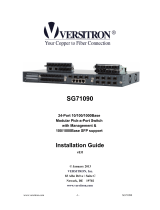
1.3 Physical Description
SP1386 / SP1387 Front View
SP1386/SP1387 M365 series M366 series
Management Board Converter Module Converter Module
RESET Button
Used to restart the system only.
LED Definition
SP1386/SP1387 Management Converter Chassis:
LED Status Operation
Steady/Green Link connected with remote device
Blink/Green Data transmitted
L/A
Off No link connected with remote device
Steady/Green Both power units at good status
Blink/Green Either power fails
A / B
Off Both powr are off or fail
M365 Series Converter Module:
Steady/Green Power On
PWR
Off Power Off
Steady/Green TP/FX link connected
LNK
Off No TP/FX link connected
Steady/Green 100M TP link connected
TP_100
Off 10M TP or No link connected
Steady/Green 100M fiber link connected
FX_100
Off No fiber link connected
3

Steady/Amber Full duplex mode
Blink/Amber Collision
FDX/COL
Off Half duplex mode
M365 Series Converter Module:
Steady/Green Power On
PWR
Off Power Off
Steady/Green TP/FX link connected
LNK
Off No TP/FX link connected
Steady/Green 1000M TP link connected
TP_1000
Off 10/100M TP or No link connected
Steady/Green 1000M fiber link connected
FX_1000
Off No fiber link connected
Steady/Amber Full duplex mode
Blink/Amber Collision
FDX/COL
Off Half duplex mode
DIP Switch (Converter Module)
M365 Series (10/100Mbps):
SW Description On Off
1 Fiber port duplex 100 Full duplex (default) 100 Half duplex
2 LFTP Enabled (default) Disabled
3 TP port duplex Full duplex (default) Half duplex
4 TP port speed 100M (default) 10M
5 TP port mode AUTO (default) FORCE
M366 Series (1000Mbps): AUTO by default.
4

2. Installation
The 16-Slot Management Converter Chassis is designed in compliance with the EIA 310-D standards and the
chassis cabinet height is 2U (3.50 inches). The power consumption of 16 modules (maximum loading) is up to
150 Watts. Sufficient air ventilation and good environment are necessary to assure proper converter chassis
operation. Consider the proper spacing between the manageable chassis and adjacent facility when mounting
the manageable chassis to the 19-inch rails.
2.1 Rack Mounting
y Wear a grounding device for electrostatic discharge.
y Install four screws through mounting ears into each side.
y Locate the 2U-high Converter Chassis at 19” mounting rails and screw up the front brackets.
2.2 Power Supply
y Each power unit has a separate power switch.
y Set power switch off at the "0" position before connecting to the power cord.
- For AC power model:
Verify that the voltage of AC power is correct and plug in AC power cord.
- For DC power model:
Verify that the voltage of DC power is correct and fasten DC power lugs
Power Input Terminal: -48VDC
FG (frame ground for 19-inch rack rail)
GND: 0V
y Turn on power A and power B switch at the "1" position.
y Slide-in power supply units are hot swappable.
2.3 Converter Module
y Wear a grounding device for electrostatic discharge.
y Unscrew and remove the vacant slot dummy panel.
y Verify the converter module is the right model and conforms to the chassis.
y Slide the module along two guides in slot and fasten the thumb knob, and be sure that the converter module
is properly seated against the slot socket/connector.
y Install the media cable for network connection.
y Slide-in converter module is hot-swappable.
Note: The slide-in modules and converter chassis should be supplied only by the same vender.
2.4 Management Board Module
y Wear a grounding device for electrostatic discharge
y Slide-in the replacement power unit along the guide rails
y Install and fasten the bolt on the plate of power unit.
y Management board module is hot swappable
5

2.5 Optional Modules
Model name Description
10/100M
M365A
10/100BASE-TX to 100BASE-FX, 2km, Multi-mode, ST, 1310nm
M365B
10/100BASE-TX to 100BASE-FX, 2km, Multi-mode, SC, 1310nm
M365B-20
10/100BASE-TX to 100BASE-FX, 20km, Single-mode, SC, 1310nm
M365B-40
10/100BASE-TX to 100BASE-FX, 40km, Single-mode, SC, 1310nm
M365B-60
10/100BASE-TX to 100BASE-FX, 60km, Single-mode, SC, 1310nm
1000M
M366B
1000BASE-T to 1000BASE-SX, 550m, Multi-mode, SC, 850nm
M366B-10
1000BASE-T to 1000BASE-LX, 10km, Single-mode, SC, 1310nm
M366B-30
1000BASE-T to 1000BASE-LX, 30km, Single-mode, SC, 1310nm
M366B-50
1000BASE-T to 1000BASE-LX, 50km, Single-mode, SC, 1310nm
6

3. Web-based User Interface
3.1 Setting up Connection
The Management Converter Chassis provides embedded HTTP engine and can be managed using a
standard Web Browser from any computer attached to the network. Factory default value of system is:
IP Address: 192.168.1.1
Subnet Mask: 255.255.255.0
Default Gateway: 192.168.1.254
Both PC/station and management board’s IP must be located in the same IP subnet.
3.2 Main Page
By default, login account for authentication is:
Username: manager
Password: manager
Note: Only one user can access the system at the same time.
7

Finish loading, main page shows all available system tools for switch management.
Device Information
It displays System Name, Contact, Hardware/Software Version, Uptime, System Location, Panel Description,
MAC Address, Software Update, and IP Address.
Click on [ Set IP ], it allows setting new IP address for the system.
Color Key
Click on
[ Color Key ], it displays the definition and status of LED color.
8

Card Summery
Click on [ Card Summary ]. It is overview of 16 slots. It displays Card Type, and TP/FX Link Status.
Refresh
Click on [ Refresh ] to refresh the status of system immediately.
Logout
Click on [ Logout ] to logout from the system.
Refreshing Interval Setting
It will refresh the status of system every configured time.
9

Management Board
Click on the image of Management Board on Web UI. Status of LED indicators can be seen.
Converter Module
Click on the image of Converter Module on Web UI. Status of LED indicators can be seen.
Click on [ Connection Information ]
. User can fill in the basic information for this module.
10

3.3 Rear Panel Information
Click on the icon of rear panel,
status of power supply, fan, and chassis can be monitored.
Chassis Temperature
It displays temperature in chassis. When it is over 50˚C, the color is altered from slate to red.
Power Input / Output
It displays voltage of input / output power.
Power Unit Status
It displays the power units are Operating or Failure. When either power fails, the color is altered from slate to
red.
Fan Speed/Status
It displays fan speed and status. When either fan fails, the color is altered from slate to red. When fan speed is
under 2000RPM, the color is altered from slate to yellow.
3.4 Manager Settings
Click on the icon of “Manager Settings” in left side of main page, system information can be configured as
follows.
11

System Name
It allows naming the system.
Location
It allows entering physical location for the device.
Contact
It allows entering a contact name for the device.
Description
It allows entering a description for the panel.
12

3.5 Configuration
Click on the icon of “Configuration” in left side of main page,
SNMP and password configuration can be done as follows.
SNMP Configuration
Simple Network Management Protocol (SNMP) is a communication protocol for managing devices on a
network. It is commonly used for network administrators to communicate with multiple devices (hub, switch,
router …) for configuring and monitoring while convenient for troubleshooting but no miscellaneous platform
consideration. SNMP agent is embedded in the system, and watches status of system. The Network
Management Station (A computer attached to network with SNMP management program well installed) can be
used for accessing to.
y Get Community: Input a name as a community string for authentication (ex. public). Read-Only
authority is available.
y Set Community: Input a name as a community string for authentication (ex. private). Read-Write
authority is available.
y Trap IP: Input an IP address of Trap Manager. Trap Manager specifies the Network Management
Stations (NMS) that will receive trap messages from the SNMP agent.
y Trap Community: Input a name as a community string for authentication (ex. public).
Note: The trap manager may not display trap messages normally, until you load the private MIB file.
Set Password
Change password for the system authentication.
13

Reboot System
Reboot the system without changing.
3.6 Trap
Click on the icon of “Configuration” in left side of main page.
It defines trap information, shows real-time system events, and provides E-mail alarm setting.
Trap Information
It lists events that will be sent for alarming.
Click on View Traplog
to look trap events that had happened.
14

Trap mail setting
y Send to E-mail address: Destination you want to send to.
y SMTP Server IP address: The server that transmits your mail.
y User Account
y Password
Trap mail menu setting
To configure the kind of trap event that needs to send e-mail alarm.
15

4. Text-based User Interface
4.1 Setup the Connection
The Management Converter Chassis provides other user interfaces to access by telnet and direct console.
The management functions of Telnet program or console are exactly the same with web-based management
interface but in text mode.
In-band Connection (Telnet)
To access the system a Telnet session, just start the Telnet program on a PC and connect to the system.
Factory default value of system is:
IP Address: 192.168.1.1
Subnet Mask: 255.255.255.0
Default Gateway: 192.168.1.254
Both PC/station and management board’s IP must be located in the same IP subnet. Press “Enter” key to
begin login screen. Enter the username and password to login the system. By default, login account for
authentication is:
Username: manager
Password: manager
Out-of-band Connection (Console)
To activate console port connection, attach a RS-232 cable (Straight-through) to the serial port of a PC running
a terminal emulation program and configure the program as follows:
Baud rate: 115200
Parity: None
Data bit: 8
Stop bit: 1
Flow control: None
Press “Enter” key to begin login screen. Enter the username and password to login the management console.
The management functions of console program are exactly the same with web-based management interface
but in text mode. By default, login account for authentication is:
Username: manager
Password: manager
16

4.2 Top Level Menu
Key “c” to display status of cards.
Key “logout” to logout from system.
17

4.3 IP Address Setting
At top level menu, key “ip” to enter IP setting level.
Setting
Key “s” to start setting of IP information.
Display
Key “d” to display IP information.
18

4.4 System Menu
At top level menu, key “s” to enter System setting level.
Display
Key “d” to display setting and system information.
19
/