Page is loading ...

GuideLed 10011 ... 11026 LED CG-S
Montage- und Betriebsanleitung GuideLed 10011 ...11026 LED CG-S
Mounting and Operating Instructions GuideLed 10011 ... 11026 LED CG-S
Zielgruppe: Elektrofachkraft
Target group: Skilled electricians
Verwendungszweck: Notbeleuchtung, nicht für privaten Gebrauch
Intended Application: Emergency Lighting, not suitable for private use

2 Montage- und Betriebsanleitung GuideLed 10011...11026 LED CG-S 40071860108 (F) www.eaton.com
DISCLAIMER OF WARRANTIES AND LIMITATION OF LIABILITY
The information, recommendations, descriptions and safety notations in this document are based on Eaton
Corporation’s (“Eaton”) experience and judgment and may not cover all contingencies. If further informa-
tion is required, an Eaton sales office should be consulted. Sale of the product shown in this literature
is subject to the terms and conditions outlined in appropriate Eaton selling policies or other contractual
agreement between Eaton and the purchaser.
THERE ARE NO UNDERSTANDINGS, AGREEMENTS, WARRANTIES, EXPRESSED OR IMPLIED, INCLUDING
WARRANTIES OF FITNESS FOR A PARTICULAR PURPOSE OR MERCHANTABILITY, OTHER THAN THOSE
SPECIFICALLY SET OUT IN ANY EXISTING CONTRACT BETWEEN THE PARTIES. ANY SUCH CONTRACT
STATES THE ENTIRE OBLIGATION OF EATON. THE CONTENTS OF THIS DOCUMENT SHALL NOT BECOME
PART OF OR MODIFY ANY CONTRACT BETWEEN THE PARTIES.
In no event will Eaton be responsible to the purchaser or user in contract, in tort (including negligence),
strict liability or other-wise for any special, indirect, incidental or consequential damage or loss whatsoev-
er, including but not limited to damage or loss of use of equipment, plant or power system, cost of capital,
loss of power, additional expenses in the use of existing power facilities, or claims against the purchaser
or user by its customers resulting from the use of the information, recommendations and descriptions con-
tained herein. The information contained in this manual is subject to change without notice.

3
Mounting and Operating Instruction GuideLed 10011...11026 LED CG-S 40071860108 (F) www.eaton.com
Inhalt
1. Normenkonformität ..................4
2. Kurzbeschreibung/Verwendungsbereich . 5
3. Ersatzteile .........................7
4. Umrüstung ........................ 8
5. Technische Daten . . . . . . . . . . . . . . . . . . 11
6. Inspektion / Wartung / Instandhaltung. .. 11
7. Entsorgung / Recycling .............. 11
Table of Contents
1. Conformity with standards ............4
2. Brief Description / Scope of Application ..5
3. Replacement Parts ..................7
4. Refitting ..........................8
5. Technical Data .................... 11
6. Servicing / Maintenance. ............ 11
7. Disposal / Recycling ................ 11
Style LED Upgrade Kit

4 Montage- und Betriebsanleitung GuideLed 10011...11026 LED CG-S 40071860108 (F) www.eaton.com
SICHERHEITSHINWEISE
• Die Leuchte ist bestim mungs gemäß in
unbeschädigtem und einwandfreiem Zu-
stand zu betreiben!
• Als Ersatz dürfen nur Originalteile von
CEAG verwendet werden!
• Bei Arbeiten an der Notleuchte ist erst
die Anlage zu blockieren, der Batterie-
kreis zu unterbrechen und dann das
Netz abzuschalten. Das Bild unten zeigt
das Hinweisschild auf der Notleuchte.
• Vor der ersten Inbetriebnahme muss die
Leuchte entsprechend den im Abschnitt
Installation genannten Anweisungen
geprüft werden!
• Die Notleuchtenkenn zeich nung vorneh-
men: Stromkreis und Leuchtennummer
zuordnen und eintragen.
• Die Protokollführung gemäß der natio-
nalen Vorschriften ist durchzuführen
(entfällt bei automatischer Protokollie-
rung)!
• Alle Fremdkörper müssen vor der ersten
Inbetriebnahme aus dem Gerät entfernt
werden!
• Beachten Sie bei allen Ar beiten an dem
Gerät die nationalen Sicherheits- und
Unfallverhütungsvorschriften und die
nachfolgenden Sicherheitshinweise in
der Betriebsanleitung, die mit einem
versehen sind!
SAFETY INSTRUCTIONS
• The device shall only be used for its
intended purpose and in undamaged
and flawless condition
• Only genuine CEAG spare parts may be
used for replacement and repair
• When working on the emergency
luminaire the system must first be
blocked, battery operation must
be interrupted and mains must be
switched off. The picture below shows
the indication label on the emergency
luminaire.
• Prior to its initial operation, the
luminaire will have to be checked in line
with the instructions (see installation
sector)
• Carry out the marking of the emergency
luminaire: Assign the circuit and the
luminaire No. and enter them.
• Recording in the minutes shall be
performed in compliance with the
national regulations (is deleted in case
of automatic recording).
• Any foreign object shall be removed
from the luminaire prior to its initial
operation!
• Observe the national safety rules and
regulations to prevent accidents as well
as the safety instructions included in
these operating instruction marked
with
1. Normenkonformität
Leuchte für Notbeleuchtung gem. EN 60 598-2-
22, zum Anschluss an Sicherheitsbeleuchtungs-
anlagen gem. DIN VDE 0100-718, EN 50 172 und
E DIN VDE 0108-100.
Gemäß ISO 9001 entwickelt, gefertigt und
geprüft.
1. Conformity with standards
Luminaire for emergency lighting acc. to EN
60 598-2-22 for connection to safety luminaire
systems acc. to DIN VDE 0100-718, EN 50 172
and E DIN VDE 0108-100.
Designed, manufactured and tested according to
DIN EN ISO 9001.

5
Mounting and Operating Instruction GuideLed 10011...11026 LED CG-S 40071860108 (F) www.eaton.com
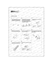
1.1 Wandmontage Aufputz 10011/11011
(Optional Einbau in Leichtbauwänden)
1.1 Wall mounting, surface 10011/11011
(Optional recessed mounting for lightweigh walls)
1. Aufbau der Leuchte / Maßbilder
20 m
10011/12
11011/12
1101110011
30 m
1. Construction / dimensional drawings
•Die Netzkabel durch die vorgesehene Kabelein-
führung (6) schieben
•Wandmontageadapter mit geeigneten Schrau-
ben an den Befestigungslöchern (4) an der
Wand fixieren (für eventuellen Einbau dieser
Leuchte dienen Befestigungslöcher 2)
•Netzkabel an das Versorgungsgerät an den
Klemmen L und N anschliessen (optional an
die Steckklemme 5)
•Adresse am Versorgungsmodul (7) einstellen
•LED-Anschlussleitung an der Rückwand der
Piktogrammscheibe (8) mit dem Versorgungs-
modul V-CG-SLS 28 (7) verbinden, (2er Steck-
klemme). Bipolarer Anschluss der LEDs - auf
eine Polung muss nicht geachtet werden!!
•Piktogrammscheibe von oben auf die Rück-
wand an den Steckfassungen (3) einschieben
•Zum Öffnen bzw. Lösen der Piktogrammschei-
be das Häkchen (1) zur Seite schieben.
•Feed mains cable through cable entries (6)
•Fix mounting adapter to wall with suitable
screws through fixing holes (4). (For recessed
wall mounting, use fixing holes 2)
•Connect mains cable to supply module at termi-
nals L and N (optional to terminal 5)
•Set the address on supply module (7)
•Connect the LED connection-cable (8),to the
supply module V-CG-SLS 28 (7).Bipolar con-
nection to LEDs - a polarity has not be ob-
served
•Slide the pictogram panel on wall mounting ad-
apter via plug-in sockets (3)
•To open the pictogram panel, push against the
fastening (1).
Rückansicht Gehäuse und Piktogramm
Back view enclosure and pictogram
7
4
5
2
3
1
6
6
8
41
33
33
41

6 Montage- und Betriebsanleitung GuideLed 10011...11026 LED CG-S 40071860108 (F) www.eaton.com
1.2 Wand-Halbeinbau 10012/11012
1.2 Semi-recessed wall mounting 10012/11012
20 m
10012 11012
30 m
•Ausschnitt (2) für eine ovale Geräte-Doppel-
dose bei 10012 und 11012 CG-S bzw. einfache
Gerätedose (Ø 60 mm, Höhe mind. 61 mm) bei
10013 und 11013 CG-S nach DIN 49073 (nicht
im Lieferumfang enthalten) erstellen
•Wandrahmen (3) an den jeweiligen 4 Bohrlö-
chern (1) an der Wand mit geeigneten Schrau-
ben befestigen
•Netzkabel anschließen, Versorgungsmodul (4)
in die Unterputzdose stecken
•Adresse am Versorgungsmodul (4) einstellen.
•Die LED-Anschlussleitung an der Rückwand
der Piktogrammscheibe Versorgungsmodul
(4) verbinden (2er Steckklemme). Bipolarer
Anschluss der LEDs - auf eine Polung muss
nicht geachtet werden!!
•Piktogrammscheibe von oben auf den Wand-
rahmen aufschieben, bis Häckchen (6) einras-
tet.
•Zum Öffnen bzw. Lösen der Piktogrammschei-
be mit einem dünnen Gegenstand (z. B. Nagel)
gegen das Häkchen (6) drücken.
•A cut-out (2) for the oval device double-junction
box for 10012 and 11012 CG-S or the simple
junction box (Ø 60 mm, height of mind. 61 mm)
for 10013 and 11013 CG-S acc. to DIN 49073
(not included in delivery).
•Fix the wall-frame (3) with suitable screws to
the wall at the 4 fixing holes (1).
•Connect the mains cable and put the supply
module (4) into the double-junction-box.
•Set the address on the supply module (4). Con-
nect the LED connection-cable, being back-
wards of the pictogram panel, to the supply
module, too. Bipolar connection to LEDs - a
polarity has not be observed!!
•Slide the pictogram panel on the wall-frame
until it (6) snaps in.
•To open the pictogram panel push against the
fastening (6) with a suitable item (e. g. a nail).
13
14
18
13
1
3
2
4
5
6

7
Mounting and Operating Instruction GuideLed 10011...11026 LED CG-S 40071860108 (F) www.eaton.com
Baldachin-Querschnitt/
Canopy section
1
•Netzkabel an der Decke durch die Kabeleinfüh-
rung (6) stecken, Deckenmontage-Adapter (2)
an den Befestigungslöchern (7) mit geeigneten
Schrauben an der Decke befestigen
•Netzkabel an das Versorgungsmodul V-CG-SLS
28 (3) anschließen (2 Steckklemmen)
•Adresse am Versorgungsmodul (3) einstellen
•Die zwei beigefügten Hülsen (5) über die LED-
Anschlussleitungen an der Piktogrammschei-
be führen, Leitungen am oberen Ende biegen
und durch die Pendelöffnung (9) schieben und
durch die Aussparung (8) in Richtung Versor-
gungsmodul führen
•Eine Leitung am Modul durch den Leitungsweg
(10) führen und beide Leitungen an der Klem-
me (11) anschließen. Bipolarer Anschluss der
LEDs - auf eine Polung muss nicht geachtet
werden
•Piktogrammscheibe an den Deckenmontage-
Adapter montieren: Adapter (6) mitsamt Hülsen
(5) in die Pendeleinführung (9) schieben und mit
Madenschrauben (4) fixieren
•Die beiden Baldachin Gehäusehälften (1) auf
den Deckenmontage-Adapter schieben.
•Feed mains cable of the ceiling trough the cable
entry (6) and fix the ceiling mounting-adapter
(2) with suitable screws at the fixing holes (7)
to the ceiling
•Connect the mains cable to the supply module
V-CG-SLS 28 (3) (2 terminals)
•Set the address on the supply module
•Lead the two enclosed bushes (5) over the
LED connection-cables of the pictogram panel
and bend them at the top (s. above), introduce
them to the pendulum holes (9) and lead them
through the recess (8) to the supply module
•Pass one cable along the cable-run (10) and con-
nect both cables to the terminal (11). Bipolar
connection to LEDs - a polarity has not be
observed
•Slide the pictogram panel onto the ceiling
mounting-adapter by introducing the bushes
(5) with the adapters (6) into it. Now fix them
with the set screws (4)
•After that, slide both canopy-halves (1) onto the
ceiling mounting-adapter.
1.3 Deckenaufbaumontage mit Baldachin
10021/11021
1.3 Ceiling mounting with canopy
10021/11021
20 m
30 m
10021 11021
Kabelbogen/
Cable bend

8 Montage- und Betriebsanleitung GuideLed 10011...11026 LED CG-S 40071860108 (F) www.eaton.com
1.4 Pendelmontage 10022..23/11022..23 1.4 Pendulum mounting mounting 10022..23/11022..23
•Netzkabel an der Decke durch die Kabelein-
führung stecken, Deckenmontage-Adapter (s.
Seite 5) an den Befestigungslöchern mit geeig-
neten Schrauben an der Decke befestigen
•Netzkabel an Versorgungsmodul V-CG-SLS 28
(2) anschließen (Steckklemme/8)
•Adresse am Versorgungsmodul einstellen
•Beiliegende Leitungsverlängerungen mit Hilfe
der Schraubklemmen anschließen.
•Die Pendelrohre (5) über die Leitungen führen
(noch nicht am Adapter/7 einrasten) und am
oberen Ende einen Kabelbogen formen
•Durch die Pendelaufnahme am Baldachin füh-
ren und durch die Aussparung wieder einfüh-
ren. Die Leuchte hängt nur an den Leitungen
•Pendelrohre auf Piktogrammscheibe stecken,
bis Nasen des Adapters (7) in den Löchern (6)
einrasten
•Pendelrohre in Montage-Adapter (2) stecken,
mit Madenschrauben (3) fixieren
•LED-Anschlussleitungen an Versorgungsmodul
anschließen. Bipolarer Anschluss der LEDs -
auf eine Polung muss nicht geachtet werden
•Beide Baldachin Gehäuse (1) auf den Decken-
montage-Adapter schieben (siehe Seite 7).
•Feed mains cable through cable entry of ceiling
mounting-adapter (s. page 5), fix it with suitable
screws at the fixing holes to the ceiling
•Connect the mains cable to the supply module
V-CG-SLS 28 (terminal/8)
•Set address on supply module
•Connect enclosed cable extensions by the help
of screw terminals
•Lead pendulum tubes (5) over the cables (do
not click into the adapter/7) and form a bend
at the top
•Lead them through the pendulum entry at the
mounting adapter and than back through the
recess. The luminaire only hangs at the cables
• Stick the pendulum tubes onto the pictogram
panel until the hooks of the adapter (7) snap in
the holes (6)
•Insert the pendulum tubes into the mounting
adapter (2), fix them with the set screws (3).
•Connect LED connection-cable to the supply
module. Bipolar connection to LEDs - a po-
larity has not be observed
•Slide both canopies (1) onto the ceiling moun-
ting-adapter. (s. page 7)
20 m
10022
11022
30 m

9
Mounting and Operating Instruction GuideLed 10011...11026 LED CG-S 40071860108 (F) www.eaton.com
1.5 Seilmontage mit Baldachin 10025/11025 1.5 Ceiling mountingwith wire suspension
10025/11025
•Das Netzkabel an der Decke durch die Kabe-
leinführung stecken und den Deckenmontage-
Adapter (s. Seite 5) an den Befestigungslöchern
mit geeigneten Schrauben an der Decke befes-
tigen.
•Das Netzkabel an das Versorgungsmodul V-CG-
SLS 28 anschließen (Steckklemme/3) und die
Adresse einstellen.
•Beiliegende Seil-Leitung durch beiliegenden
Halter (1) führen. Danach die Leitung durch
die Pendeleinführung des Deckenmontage-
Adapters führen und durch die Aussparung (2)
wieder einführen.
•Den Halter in die Pendeleinführung stecken
und mit den Madenschrauben (4) befestigen.
•Nun die Feinjustage am Seilhalter durch Ein-
drücken der Hülse durchführen. Die LED-An-
schlussleitungen ggf. Ablängen, Aderendhülse
anbringen und an das Versorgungsmodul an-
schließen. Bipolarer Anschluss der LEDs - auf
eine Polung muss nicht geachtet werden!!
• Abschließend die beiden Baldachin Gehäuse
auf den Deckenmontage-Adapter schieben.
•Feed mains cable through the cable entry of the
ceiling mounting-adapter and fix it with suitable
screws at the fixing holes to the ceiling
•Connect the mains cable to the supply module
V-CG-SLS 28 (terminal/3) and set the address
•Lead enclosed wiring cables through enclosed
fastener (1). Than insert the cables through the
pendulum entries of the ceiling mounting-adap-
ter and lead them back through the recess (2).
•Put the fastener into the pendulum holes and
fix them with the set screws (4).
•Do the fine adjustment at the wire holder by
pressing the bush. If necessary cut the LED
connection-cables into lengths, fix conductor
sleeves and connect them to the supply modu-
le. Bipolar connection to LEDs - a polarity has
not be observed
•After that, slide both canopies onto the ceiling
mounting-adapter.
20 m
10025
11025
30 m
2
3
4
1
4

10 Montage- und Betriebsanleitung GuideLed 10011...11026 LED CG-S 40071860108 (F) www.eaton.com
1.6 Seilmontage Deckeneinbau 10026/11026 1.6 Recessed ceiling mounting with wire
10026/11026
•Beide Seilhalter in beiliegende Gewindehülsen
(3) einschrauben
•Diese in der Decke befestigen mit Unterleg-
scheibe und Mutter (Abstand s. Maßbild), Seile
hindurch schieben.
•Beiden Seile und Netzkabel an den seitlichen,
ausbrechbaren Leitungseinführungen (2) in den
Modulträger (1) einführen und mit Hilfe der Zug
entlastungen fixieren.
•Abhängeseile mit dem Anschlussadapter ver-
binden, Adapter am LED-Konverter einstecken
•Netzleitung an den Klemmen L und N anschlie-
ßen
•Adresse am Modul einstellen
•Deckel auf den Modulträger einrasten lassen.
Nach Feinjustierung der Abhängehöhe die Ma-
denschrauben am Bolzen festziehen.
•Screw both enclosed fastener into the bushes
(3) and fix them with the washer and the nut to
the ceiling (distance see dimensional drawing)
and put the wires through
•Introduce the wires as well as the mains cable
through the breakable cable entry sidewise (2)
and fix them by the help with the strain-reliefs
•Connect the wires to the adapter, plug in the
adapter to the LED-converter
•Connect mains cable safely with the terminals
N and L
•Set the address to the module
•Close cover to the mounting plate and after fine
adjustment of the suspension height fix the set
screws.
1
2
2
3
201
35
Bohrdurch-
messer
18 mm

11
Mounting and Operating Instruction GuideLed 10011...11026 LED CG-S 40071860108 (F) www.eaton.com
1.7 Deckeneinbaumontage 10026/11026 1.7 Recessed ceiling mounting 10026/11026
•Deckenausschnitt lt. Maßbild durchführen
•Die Kabel durch das Deckeneinbau-Gehäuse
(1) führen. Dieses im Deckenausschnitt befes-
tigen, indem die Feststellschrauben (2) gelöst
werden und die beiliegenden Krallen von innen
in den Schlitz geführt werden.
•Die Krallen bis zur Verdickung durchschieben,
Feststellschrauben eindrehen. Die Krallen sen-
ken sich ab, das Einbau-Gehäuse sitzt fest
•Netzkabel an der Steckklemme (5) befestigen,
wie auch die mitgelieferte Netzleitung.
•LED-Anschlussleitungen durch Kabeleinfüh-
rung der Abdeckblende (6) schieben
•Piktogrammscheibe an Abdeckblende durch
Einrasten der 2 Adapter (7) befestigen
•Nach Einschnappen des LED-Piktogramms in
der Deckeneinbaublende auf beiden Seiten die
beiliegenden Hülsen über die Leitung zu führen
und in Befestigungsclip zu schieben (10).
•Die Abdeckblende an den Abhängesicherungen
(4) einhängen, LED-Anschlussleitungen an das
Versorgungsmodul anschließen und Adresse
einstellen. Bipolarer Anschluss der LEDs - auf
eine Polung muss nicht geachtet werden!!
•Die beiden Abdeckplättchen (9) von der Blen-
de entfernen und aufbewahren. Die mitgelie-
ferte Netzleitung nun ans Versorgungsmodul
anschließen. Die Piktogrammscheibe mit der
Blende auf den Deckeneinbau setzen (Achtung,
keine Leitungen einklemmen!), mit Schrauben
(3) die Blende befestigen und die Abdeckplätt-
chen (9) auf die Schraublöcher stecken.
Make a ceiling cut-out acc. to the dimensional
drawings. Introduce mains cable through the re-
cessed ceiling mounting-enclosure (1). Fix it in
the cut-out by loosing the fixing screws (2) and
push the enclosed claws into the slots from in-
side. Push the claws against the slub and tighten
the screws. The claws spread out and affixes the
mounting enclosure. Connect the mains cable to
the terminal (5) as well as the enclosed mains
cable. Insert the LED-connection cables to the
cables entries of the cover frame (6). Fix the
pictogram panel to the cover frame until the 2
adapter (7) snap in. After snapping the LED pa-
nel into the bezel the included sleeves have to
be lead over the cables on both sides and after
that be slid into the fixing clips (10). Fit the cover
frame to the plastic safety-strips (4). Connect the
LED-connection cables to the supply module V-
CG-SLS 28 and set the address. Bipolar connec-
tion to LEDs - a polarity has not be observed!!
Remove the two blanks (9) from the cover frame
and put them aside. Connect the enclosed mains
cable to the supply module. Put the pictogram pa-
nel with the cover frame onto the ceiling insertion
by observing not to clamp the cables, fix it with
screws (3) and put the blanks on the screw-holes.
9
8
1
7
6
5
4
3
2
1
10

12 Montage- und Betriebsanleitung GuideLed 10011...11026 LED CG-S 40071860108 (F) www.eaton.com
4.2 Adressierung
• Vor Montage der Scheibe individuelle Leuch-
tenadressierung einstellen
• Mit geeignetem Schraubendreher die ge-
wünschte Adresse (1 - 20) am Adressschalter
einstellen
• Soll Leuchte nicht überwacht werden, Stel-
lung 0/0 einstellen.
4.2 Adressing
• Before fitting the screen or cover, the addres-
sing of the individual luminaires must be
completed
• The desired address (1-20) is set on the
address switch using a screwdriver
• If the luminaire should not be monitored,
select code 0/0.
4. Kurzbeschreibung / Verwendungs-
bereich
Die Rettungszeichenleuchten GuideLED CG-S
sind für den Betrieb an CEAG Sicherheitsbe-
leuchtungsanlagen nach EN 50 172, DIN VDE
0100-718 und E DIN VDE 0108-100 geeignet. Die
besondere Schalt- und Überwachungsfunktion
wird nur mit CEAG CG-S-Technologie ermög-
licht.
4.1 Montage
Eine genaue Beschreibung erhalten Sie auf den
Seiten 3-8.
4. Brief description / Scope of appli-
cation
The exit luminaires GuideLED CG-S are suitable
for operation on CEAG emergency lighting sy-
stems acc. to EN 50 172, DIN VDE 0100-718 and
E DIN VDE 0108-100 . The advanced switching
and monitoring mode is only available in combi-
nation with CEAG CG-S-technology.
4.1 Mounting
Find the detailed description on the pages 3-5.
Adressschalter 1
address switch 1
Adressschalter 2
address switch 2
Leuchtenadresse
Luminaire address
0 0 Überwachung aus / Monitoring off
0 1 1
0 2 2
..... ..... .....
1 0 10
1 1 11
1 2 12
..... ..... .....
2 0 20
2 1 nicht zul. / not permissable
2 2 nicht zul. / not permissable
..... ..... .....
2 9 nicht zul. / not permissable
Adressschalter
adress switch

13
Mounting and Operating Instruction GuideLed 10011...11026 LED CG-S 40071860108 (F) www.eaton.com
5. Technische Daten
5. Technical Data
Anschlussspannung
Power input
220 - 240 V AC, 50/60 Hz, 176 - 275 V DC
Erkennungsweite
Viewing distance
20 m und 30 m
20 m and 30 m
Gehäusematerial
Housing material
PC, PMMA
Gehäusefarbe
Housing colour
lichtgrau RAL 7035
light-grey RAL 7035
Standby Verlustleistung
Standby power loss
0,5 W (230 V / 50 Hz)
Lichtstrom phiE/phiNenn am
Ende der Nennbetriebsdauer
Luminous flux phiE/phiNenn at
the end of rated operating time
100%
Leuchtmittel
Light source
LED-Leiste mit 3-Chip-LEDs
LED-strip with 3 chip LEDs
Anschlussleistung Netzbetrieb (Scheinleistung/Wirkleistung)
Power consumption mains operation (apparent/effective power)
20 m
8 mA / 12 mA
einseitig 4,0 VA/ 1,9 W
zweiseitig 5,5 VA / 2,9 W
30 m
11 mA / 17 mA
einseitig 5,0 VA/ 2,6 W
zweiseitig 7,1 VA / 4,1 W
Nennlichtstrom 21011 SL R
Luminous flux 21011 SL O
305 lm
410 lm
Schutzklasse
Insulation class
II (I bei Einbauvarianten)
II (I for recessed variants)
Schutzart nach EN 60529
Protection category acc. to EN 60529
IP40
Umgebungstemperatur
Permissable ambient temperature
-10 °C .. +40 °C
Netzanschlussklemmen
Terminals
Steckklemme 2,5 mm
2
plug-in terminal 2.5 mm
2
Gewicht
Weight
10011 CG-S 0,47kg
10012 CG-S 0,41kg
10013 CG-S 0,41kg
10021 CG-S 0,39kg
10022 CG-S 0,49kg
10023 CG-S 0,54kg
10024 CG-S 0,70kg
10025 CG-S 0,40kg
10026 CG-S 0,41kg
11011 CG-S 0,60kg
11012 CG-S 0,56kg
11013 CG-S 0,56kg
11021 CG-S 0,79kg
11022 CG-S 0,94kg
11023 CG-S 0,99kg
11024 CG-S 1,22kg
11025 CG-S 0,81kg
11026 CG-S 0,82kg
6. Wartung / Instandhaltung
Halten Sie die für Instandhaltung, Wartung und
Prüfung von elektrischen Betriebsmitteln gel-
tenden Bestimmungen ein! Bei sachgerechtem
Betrieb und unter Beachtung der Montagehin-
weise und Umgebungsbedingungen ist keine
ständige Wartung erforderlich.
7. Entsorgung / Recycling
Beachten Sie bei der Entsorgung defekter Geräte
die gültigen Vorschriften hinsichtlich Recycling
und Entsorgung. Kunststoffmaterialien sind mit
entsprechenden Symbolen gekennzeichnet.
6. Servicing / Maintenance
Observe the relevant national regulations
applying to the maintenance, servicing and
check-ing of electrical apparatus ! If installed
and operated correctly in the right environmen-
tal conditions, no permanent servicing will be
required.
7. Disposal / Recycling
When a defective apparatus is disposed of, the
respective national regulations on waste disposal
and recycling must be observed. Plastic parts have
been provided with respective symbols.

14 Montage- und Betriebsanleitung GuideLed 10011...11026 LED CG-S 40071860108 (F) www.eaton.com

15
Mounting and Operating Instruction GuideLed 10011...11026 LED CG-S 40071860108 (F) www.eaton.com

Eaton Industries Manufacturing GmbH
Electrical Sector EMEA
Route de la Longeraie
71110 Morges, Switzerland
Eaton.eu
CEAG Notlichtsysteme GmbH
Senator-Schwartz-Ring 26
59494 Soest
www.ceag.de
© 2013 Eaton
All Rights Reserved
Printed in Germany
Publication No. 40071860226/WK
Oktober 2013
Eaton is a registered trademark.
All trademarks are property
of their respective owners.
Eatons Ziel ist es, zuverlässige, effiziente und sichere
Stromversorgung dann zu bieten, wenn sie am meisten
benötigt wird. Die Experten von Eaton verfügen über ein
umfassendes Fachwissen im Bereich Energiemanagement
in verschiedensten Branchen und sorgen so für kundens-
pezifische, integrierte Lösungen, um anspruchsvollste
Anforderungen der Kunden zu erfüllen.
Wir sind darauf fokussiert, stets die richtige Lösung
für jede Anwendung zu finden. Dabei erwarten
Entscheidungsträger mehr als lediglich innovative Produkte.
Unternehmen wenden sich an Eaton, weil individuelle
Unterstützung und der Erfolg unserer Kunden stets an
erster Stelle stehen. Für mehr Informationen besuchen Sie
www.eaton.eu.
Eaton is dedicated to ensuring that reliable, efficient
and safe power is available when it’s needed most. With
unparalleled knowledge of electrical power management
across industries, experts at Eaton deliver customized,
integrated solutions to solve our customers’ most critical-
challenges.
Our focus is on delivering the right solution for the appli-
cation. But, decision makers demand more than just
innovative products. They turn to Eaton for an unwavering
commitment to personal support that makes customer
success a top priority. For more information, visit www.
eaton.com/electrical.
/