Page is loading ...

_______________________________________________________________________________________________________________________________
European Safety Systems Ltd. Impress House, Mansell Road, Acton, London W3 7QH [email protected]m Tel: +44 (0)208 743 8880
www.e2s.com Fax: +44 (0)208 740 4200
Document No. D211-00-201-IS-SC Issue B 27-09-17 Sheet 1 of 6
INSTRUCTION MANUAL
D2xB1X05 & D2xB1X10 Xenon Beacons
For use in Hazardous Locations
1) Warnings
• DO NOT OPEN WHEN AN EXPLOSIVE
ATMOSPHERE IS PRESENT
• DO NOT OPEN WHEN ENERGISED
• POTENTIAL ELECTROSTATIC CHARGING
HAZARD - CLEAN ONLY WITH A DAMP
CLOTH
• HIGH VOLTAGE SHOCK HAZARD. WAIT 5
MINUTES AFTER REMOVING POWER
BEFORE OPENING THE ENCLOSURE
Avertissement:
• NE PAS OUVRIR UN PRESENCE
D’ATMOSPHERE EXPLOSIVE
• NE PAS OUVRIR ENERGIE
• DANGER POTENTIEL CHARGE
ÉLECTROSTATIQUE - NETTOYER
UNIQUEMENT AVEC UN CHIFFON HUMIDE
• HAUT TENSION, RISK DE CHOC.
ATTENDEZ 5 MINUTES APRES AVOIR
DEBRANCHE L’ALIMENTATION AVANT
D’OUVRIR LA BOITIER
2) Rating & Marking Information
2.1 Fire Alarm Ratings
The Following models are certified as visual alarm devices
for fire alarm use – private mode when used with clear or red
lens covers:
D2xB1X05DC024 / D2xB1X05DC048
D2xB1X10DC024 / D2xB1X10DC048
On-axis light output per UL1638:
Model
Lens cover colour
Light output in cd
D2xB1X05DC024
clear
22.2
red
9.2
D2xB1X05DC048
clear
30
red
12
D2xB1X10DC024
clear
73.8
red
20.4
D2xB1X10DC048
clear
82
red
26
2.2 surge current ratings for use in fire alarm systems
Model
Peak Surge current
RMS surge current
D2xB1X05DC024
5.86A
745mA
D2xB1X05DC048
12.7A
1.45A
D2xB1X10DC024
6.2A
871mA
D2xB1X10DC048
14.5A
780mA
2.3 NEC & CEC Class / Division Ratings for US / Canada
The D2xB1X05 and D2xB1X10 Xenon beacons comply with
the following standards:
ANSI/ISA 12.12.01-2015
CSA C22.2 No. 213-16
The D2xB1X05 Xenon Beacon is rated as follows:
Class I Div 2 ABCD T3 Ta -40°C to +50°C
Class II Div 2 FG T5 Ta -40°C to +50°C
Class II Div 2 FG T6 Ta -40°C to +40°C
Class III Div 1&2 Ta -40°C to +50°C
The D2xB1X10 Xenon Beacon is rated as follows:
Class I Div 2 ABCD T2B Ta -40°C to +50°C
Class II Div 2 FG T5 Ta -40°C to +50°C
Class II Div 2 FG T6 Ta -40°C to +40°C
Class III Div 1&2 Ta -40°C to +50°C
Installation must be carried out in compliance with the
National Electric Code / Canadian Electric Code
2.4 NEC Class / Zone ratings US
The D2xB1X05 and D2xB1X10 Xenon beacons comply with
the following standards:
UL 60079-0-2013
UL 60079-15-2013
UL 60079-31-2015
The D2xB1X05 Xenon Beacon is rated as follows:
Class I Zone 2 AEx nA IIC T3 Gc Ta -40°C to +50°C
Zone 22 AEx tc IIIC 95°C Dc Ta -40°C to +50°C
The D2xB1X10 Xenon Beacon is rated as follows:
Class I Zone 2 AEx nA IIC T2 Gc Ta -40°C to +50°C
Zone 22 AEx tc IIIC 95°C Dc Ta -40°C to +50°C
Installation must be carried out in compliance with the
National Electric Code.

_______________________________________________________________________________________________________________________________
European Safety Systems Ltd. Impress House, Mansell Road, Acton, London W3 7QH [email protected]m Tel: +44 (0)208 743 8880
www.e2s.com Fax: +44 (0)208 740 4200
Document No. D211-00-201-IS-SC Issue B 27-09-17 Sheet 2 of 5
2.5 CEC Class / Zone ratings Canada
The D2xB1X05 and D2xB1X10 Xenon beacons comply with
the following standards:
CAN/CSA C22.2 No. 60079-0:2015
CAN/CSA C22.2 No. 60079-15:2016
CAN/CSA C22.2 No. 60079-31:2015
The D2xB1X05 Xenon Beacon is rated as follows:
Ex nA IIC T3 Gc X Ta -40°C to +50°C
Ex tc IIIC 95°C Dc X Ta -40°C to +50°C
The D2xB1X10 Xenon Beacon is rated as follows:
Ex nA IIC T2 Gc X Ta -40°C to +50°C
Ex tc IIIC 95°C Dc Ta -40°C to +50°C
Installation must be carried out in compliance with the
Canadian Electric Code
2.6 ATEX / IECEx certification
The D2xB1X05 and D2xB1X10 xenon beacons comply with
the following standards:
EN60079-0:2012+A11:2013 / IEC60079-0: ed. 6.0 (2011-06)
EN60079-15:2010 / IEC60079-15: ed. 4.0 (2010-01)
EN60079-31:2014 / IEC60079-31:2013 ed. 2.0 (2013-11)
Certificate No. DEMKO 14 ATEX 4786493904X
IECEx ULD 14.0004X
The D2xB1X05 Xenon Beacon is rated as follows:
The D2xB1X10 Xenon Beacon is rated as follows:
CE Marking
Zones, Gas / Dust Groups and Temperature
Classification
When connected to an approved system the D2X alarm horn
may be installed in:
Zone 2 explosive gas air mixture not likely to occur
in normal operation, and if it does, it will only exist
for a short time.
Zone 22 explosive dust air mixture not likely to occur
in normal operation, and if it does, it will only exist
for a short time.
May be used with gases in groups:
Group IIA propane
Group IIB ethylene
Group IIC hydrogen / acetylene
Having a temperature classification
(for Gas applications) of:
T1 450ºC
T2 300ºC
T3 200ºC (D2xB1X05 only)
May be used with Dust types:
Group IIIA combustible flyings
Group IIIB non-conductive dust
Group IIIC conductive dust
Maximum Surface Temperature for Dust Applications:
95°C
Installation must be carried out in compliance with the latest
issue of the following standards:
EN60079-14 / IEC60079-14: Explosive atmospheres -
Electrical installations design, selection and erection
EN60079-10-1 / IEC60079-10-1: Explosive atmospheres -
Classification of areas. Explosive gas atmospheres
EN60079-10-2 / IEC60079-10-2: Explosive atmospheres –
Classification of areas. Explosive dust atmospheres
2.7 Ingress Protection Ratings
The product is rated for ingress Protection as follows:
IP rating: IP66
Type rating per UL50E / NEMA250: 4 / 4X / 3R / 13
To maintain the ingress protection rating, the two off cable
entries must be fitted with suitably rated, certified cable entry
and/or blanking devices during installation.
2.8 Electrical Ratings
Model No.
Voltage Range
Operating rms current
D2xB1X05DC024
24Vdc
275mA
D2xB1X05DC048
48Vdc
145mA
D2xB1X05AC115
115-120Vac
50/60Hz
80mA
D2xB1X05AC230
220-230Vac
50/60Hz
30mA
D2xB1X10DC024
24Vdc
560mA
D2xB1X10DC048
48Vdc
260mA
D2xB1X10AC115
115-120Vac
50/60Hz
185mA
D2xB1X10AC230
220-230Vac
50/60Hz
107mA
It is important that a suitable power supply is used to run the
equipment. The power supply selected must have the
necessary capacity to provide the input current to all the
units.
The input current will vary according to the voltage input
level. The current levels shown above are for the worst-case
input voltage resulting in max. current.
0518
II 3G Ex nA IIC T3 Gc Ta -40°C to +50°C
II 3D Ex tc IIIC 95°C Dc Ta -40°C to +50°C
II 3G Ex nA IIC T2 Gc Ta -40°C to +50°C
II 3D Ex tc IIIC 95°C Dc Ta -40°C to +50°C

_______________________________________________________________________________________________________________________________
European Safety Systems Ltd. Impress House, Mansell Road, Acton, London W3 7QH [email protected]m Tel: +44 (0)208 743 8880
www.e2s.com Fax: +44 (0)208 740 4200
Document No. D211-00-201-IS-SC Issue B 27-09-17 Sheet 3 of 5
116,0mm [4,52in.]
116,0mm [4,52in.]
179,2mm [6,99in.]
130,1mm [5,07in.]
132,4mm [5,17in.]
Ø6,92mm [Ø0,270in.]
3/4" NPT
(For pole mount)
M4 X 12mm
Countersunk screw,
customer to fix
3) Special Conditions of Use
Special Condition for safe Use as stated on the Type
Examination Certificate DEMKO 14 ATEX 4786493904X /
CoC IECEx ULD 14.0004X:
When used for a Group III application, the surface of the
enclosure may store electrostatic charge and become a
source of ignition in applications with a low relative humidity
<~30% relative humidity where the surface is relatively free of
surface contamination such as dirt, dust, or oil.
Guidance on protection against the risk of ignition due to
electrostatic discharge can be found in EN TR50404 and IEC
TR60079-32.
End user shall adhere to the manufacturer’s installation and
instruction when performing housekeeping to avoid the
potential for hazardous electrostatic charges during cleaning,
by using a damp cloth.
To maintain the ingress protection rating and mode of
protection, the cable entries must be fitted with suitably rated,
certified cable entry and/or blanking devices during
installation. If conduit is used for installation, seal conduit
within 18 inches from the enclosure.
4) Location and Mounting
The location of the beacon should be made with due regard
to the area over which the warning signal must be visible. It
should only be fixed to services that can carry the weight of
the unit.
The D2x beacon should be secured to any flat surface using
the two 7mm fixing holes in the feet of the base. The 2-off
feet must first be fitted to the base using the 2-off M4 X
12mm countersunk screws provided. The unit can also be
pole mounted using the ¾” NPT Entry in the centre of the
base. See Fig. 1.
Fig. 1 Fixing Location for Beacon
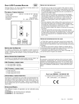
5) Access to the Enclosure
To access the enclosure, loosen the four M4 posi pan head
screws and withdraw the cover.
Fig. 2 Accessing the Enclosure.
To replace cover, check that the ‘O’ ring seal is in place.
Carefully push the cover in place. Insert and tighten down M4
screws, spring and plain washers in the order shown above
and tighten down.
6) Selection of Cable. Cable Glands, Blanking
Elements & Adapters
When selecting the cable size, consideration must be given
to the input current that each unit draws (see Table 1), the
number of sounders on the line and the length of the cable
runs. The cable size selected must have the necessary
capacity to provide the input current to all of the sounders
connected to the line.
The entries can be ordered with one of the following options:
2-off M20 x 1.5 thread, 2-off ½” NPT thread & 1-off ¾” NPT
thread
If a high IP (Ingress Protection) rating is required then a
suitable sealing washer must be fitted under the cable glands
or blanking plugs.
For use in explosive dust atmospheres, a minimum ingress
protection rating of IP6X must be maintained.
For use in explosive gas atmospheres, a minimum ingress
protection rating of IP54 must be maintained.
NPT plugs should be greased before insertion.
7) Cable Connections
Electrical connections are to be made into the terminal blocks
on the PCBA located in the enclosure. See section 5 of this
manual for access to the enclosure.
Wires having a cross sectional area between 0.5 mm² to
2.5mm² can be connected to each terminal way. If an input
and output wire is required the 2-off Live/Neutral or +/-
terminals can be used. If fitting 2-off wires to one terminal
way the sum of the 2-off wires must be a maximum cross
sectional area of 2.5mm². Strip wires to 8mm. Wires may also
be fitted using ferrules. Terminal screws need to be tightened
down with a tightening torque of 0.56 Nm / 5 Lb-in. When
connecting wires to the terminals great care should be taken
to dress the wires so that when the cover is inserted into the
chamber the wires do not exert excess pressure on the
terminal blocks. This is particularly important when using
cables with large cross sectional areas such as 2.5mm².
Warning – Hot surfaces. External surfaces
and internal components may be hot after
operation, take care when handling the
equipment.
Warning – High voltage may be present,
risk of electric shock. DO NOT open when
energised, disconnect power before
opening.
(Appropriate cable
entry devices to be
customer supplied)
Cover
4-off
M4 Cover
Screws

_______________________________________________________________________________________________________________________________
European Safety Systems Ltd. Impress House, Mansell Road, Acton, London W3 7QH [email protected]m Tel: +44 (0)208 743 8880
www.e2s.com Fax: +44 (0)208 740 4200
Document No. D211-00-201-IS-SC Issue B 27-09-17 Sheet 4 of 5
- +
COM
LL NN
COM
L
N
L L N N L L N N L L NN
-
+
- -
+ +
- -
+ +
- -
+ +
8) AC Wiring
3-off 2-way terminal blocks are provided on the AC beacon
for power. There are 2-off Live, 2-off Neutral and 2-off Earth
terminals in total.
8.1 Wiring Diagrams
Fig 3. D2xB1X05/D2xB1X10 AC Simplified Block Diagram
Fig. 4 D2xB1X05/D2xB1X10 AC Terminals
9) DC Wiring
3-off 2-way terminal blocks are provided on the AC beacon
for power. There are 2-off +ve, 2-off -ve and 2-off Earth
terminals in total.
9.1 Wiring Diagrams
Fig. 5 D2xB1X05/D2xB1X10 DC Simplified Block Diagram
Fig. 6 D2xB1X05/D2xB1X10 DC Terminals
9.2 Line Monitoring
On D2xB1X05/D2xB1X10 DC units, DC reverse line
monitoring can be used if required. All DC beacons have a
blocking diode fitted in their supply input lines. An end of line
monitoring resistor can be connected across the +ve and –ve
terminals. If an end of line resistor is used it must have the
following values:
24V DC Beacons
Minimum resistance 3K9 Ohms Minimum Power 0.5W
Minimum resistance 1K Ohms Minimum Power 2.0W
48V DC Beacons
Minimum resistance 15K Ohms Minimum Power 0.5W
Minimum resistance 3K9 Ohms Minimum Power 2.0W
The resistor must be connected directly across the +ve and
-ve terminals as shown in the following drawing. Form the
resistor legs as shown in Fig. 8a, remove the +ve and –ve
terminal plugs and fit the resistor across the two terminal
plugs before refitting them to the PCBA as shown in Fig. 8b.
A spacing of at least 1/16” (1.58mm) must be provided
through air and over surfaces between uninsulated live parts.
Fig. 7 End of Line Resistor Forming

_______________________________________________________________________________________________________________________________
European Safety Systems Ltd. Impress House, Mansell Road, Acton, London W3 7QH [email protected]m Tel: +44 (0)208 743 8880
www.e2s.com Fax: +44 (0)208 740 4200
Document No. D211-00-201-IS-SC Issue B 27-09-17 Sheet 5 of 5
Fig. 8 End of Line Resistor Placement
10) Interchangeable & Spare Parts
The Beacon lens cover is interchangeable, contact E2S Ltd for a
replacement lens cover available in various colours.
To change the lens cover, unscrew the 4-off M5 posi pan head
screws, spring and flat washers using a screwdriver. Remove the
wire guard and replace the old lens cover with the new lens cover.
Fig. 9 Replacement of beacon lens cover
Fit the wire guard back onto the housing, over the new lens cover
aligning the fixing holes of the guard, lens cover and housing. Refit
the fixings to hold into place, the fixings MUST be fitted in the order
shown above.
11) Maintenance, Overhaul & Repair
Maintenance, repair and overhaul of the equipment should
only be carried out by suitably qualified personnel in
accordance with the current relevant standards:
EN60079-19
IEC60079-19
Explosive atmospheres - Equipment repair,
overhaul and reclamation
EN 60079-17
IEC60079-17
Explosive atmospheres - Electrical
installations inspection and maintenance
To avoid a possible ELECTROSTACTIC CHARGE the unit
must only be cleaned with a damp cloth.
Units must not be opened while an explosive atmosphere is
present.
If opening the unit during maintenance operations a clean
environment must be maintained and any dust layer removed
prior to opening the unit.
Warning – Hot surfaces. External surfaces
and internal components may be hot after
operation, take care when handling the
equipment.
End of Line Resistor
M5 screw
M5 spring washer
M5 flat washer
- +

/