Page is loading ...

_______________________________________________________________________________________________________________________________
European Safety Systems Ltd. Impress House, Mansell Road, Acton, London W3 7QH sales@e-2-s.com Tel: +44 (0)208 743 8880
www.e-2-s.com Fax: +44 (0)208 740 4200
Document No.D210-00-401-IS Issue 1 02-08-16 Sheet 1 of 6
INSTRUCTION MANUAL (ATEX / IECEx)
BExBGL2D LED BEACON
For use in Flammable Gas and Dust Atmospheres
1) Warnings
• DO NOT OPEN WHEN AN EXPLOSIVE
ATMOSPHERE IS PRESENT
• DO NOT OPEN WHEN ENERGIZED
• POTENTIAL ELECTROSTATIC CHARGING
HAZARD
• COVER BOLTS CLASS A4-80
• USE HEAT RESISTING CABLES AND CABLE
GLANDS (RATED 110°C) AT AMB.
TEMPERATURES OVER 40°C
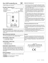
2) Rating & Marking Information
All units have a rating label, which carries the following
important information:-
Model No.: BExBGL2D
Input Voltage: DC Units 24V
AC Units 115V or 230V
BExBGL2 Codes:
Ex d IIC T6 Gb Ta. -50 to +60°C
Ex d IIC T5 Gb Ta. -50 to +70°C
Ex tb IIIC T60°C Db Ta. -50 to +40°C
Ex tb IIIC T75°C Db Ta. -50 to +55°C
Ex tb IIIC T90°C Db Ta. -50 to +70°C
Certificate No. KEMA 00ATEX2006X
IECEx KEM 10.0002X
The units can be installed in locations with the following
conditions:
Area Classification Gas:
Zone 1
Explosive gas air mixture likely to occur in
normal operation.
Zone 2
Explosive gas atmosphere not likely to
occur in normal operat
ion but may be
present for short periods.
Gas Groupings:
Group IIA
Propane
Group IIB
Ethylene
Group IIC
Hydrogen and Acetylene
Temperature Classification:
T1
450ºC
T2
300ºC
T3
200ºC
T4
135ºC
T5
100ºC
T6
85ºC (up to 65°C ambient)
Area Classification Dust:
Zone 21
Explosive dust air mixture likely to occur in
normal operation.
Zone 22
Explosive dust air mixture not likely to
occur in normal operation, and if it does, it
will only exist for a short time.
Dust Groupings:
Group IIIA
Combustible Dusts
Group IIIB
Non-Conductive Dust
Group IIIC
Conductive Dust
Maximum Surface Temperature for Dust Applications:
90ºC
IP Rating: IP66/67 to EN/IEC60529 and IP6X to
EN/IEC60079-0, EN/IEC60079-31
Equipment Category: 2G / 2D
Equipment Protection Level: Gb / Db
Ambient Temperature Range:
-50°C to +70°C Gas Groups IIA, IIB and IIC
-50°C to +70°C Dust Groups IIIA, IIIB and IIIC
0518
II 2G
II 2D
Epsilon x
Equipment Group and
Category:
CE Marking
Notified Body No.
BExBGL2D

_______________________________________________________________________________________________________________________________
European Safety Systems Ltd. Impress House, Mansell Road, Acton, London W3 7QH sales@e-2-s.com Tel: +44 (0)208 743 8880
www.e-2-s.com Fax: +44 (0)208 740 4200
Document No. D201-00-401-IS Issue 1 02-08-16 Sheet 2 of 6
3) Type Approval Standards
The beacon carries an EC Type Examination Certificate and
IECEx Certificate of Conformity, and have been certified to
comply with the following standards:
EN60079-0:2012+A11:2013 / IEC60079-0:2011 (Ed 6):
Explosive Atmospheres - Equipment. General requirements
EN60079-1:2007 / IEC60079-1:2007 (Ed 6):
Explosive Atmospheres - Equipment protection by flameproof
enclosures "d"
EN 60079-31:2014 / IEC 60079-31:2013 (Ed 2):
Explosive Atmospheres - Equipment dust ignition protection
by enclosure "t"
4) Installation Requirements
The beacon must only be installed by suitably qualified
personnel in accordance with the latest issues of the relevant
standards:
EN60079-14 / IEC60079-14: Explosive atmospheres -
Electrical installations design, selection and erection
EN60079-10-1 / IEC60079-10-1: Explosive atmospheres -
Classification of areas. Explosive gas atmospheres
EN60079-10-2 / IEC60079-10-2: Explosive atmospheres –
Classification of areas. Explosive dust atmospheres
The installation of the equipment must also be in accordance
with any local codes that may apply and should only be
carried out by a competent electrical engineer who has the
necessary training.
5) Special Conditions of Use
Repair of the flamepath / flameproof joints is not permitted.
The enclosure is non-conducting and may generate an
ignition-capable level of electrostatic charges under certain
extreme conditions (such as high-pressure steam). The user
should ensure that the equipment is not installed in a location
where it may be subjected to external conditions that might
cause a build-up of electrostatic charges on non-conducting
surfaces.
Additionally, cleaning of the equipment should be done only
with a damp cloth.
6) Location and Mounting
The location of the beacon should be made with due regard
to the area over which the warning signal must be visible.
They should only be fixed to services that can carry the
weight of the unit.
The BEx beacon should be secured to any flat surface using
the three 7mm fixing holes on the stainless steel U shaped
mounting bracket. See Figure 1. The required angle can be
achieved by loosening the two large bracket screws in the
side of the unit, which allow adjustment of the beacon in
steps of 18°. On completion of the installation then two large
bracket adjustment screws on the side of the unit must be
fully tightened to ensure that the unit cannot move in service.
Fig 1. Fixing Location for Beacon
7) Access to the Flameproof Enclosure
To access the Ex d chamber, remove the four M6 hexagon
socket head screws and withdraw the flameproof cover taking
extreme care not to damage the flameproof joints in the
process. M6 cover screws are Class A4-80 stainless steel
and only screws of this category can be used for the
enclosure.
Fig. 2 Accessing the Explosion proof Enclosure.
On completion of the installation, the flameproof joints should
be inspected to ensure that they are clean and that they have
not been damaged during installation.
Check that the earth bonding wire between the two castings
is secure and the ‘O’ ring seal is in place. When replacing the
flameproof cover casting ensure that it is square with the
flameproof chamber casting before inserting. Carefully push
the cover in place allowing time for the air to be expelled.
Only after the cover is fully in place should the four M6
Stainless Steel A4-80 cover bolts and their spring washer be
inserted and tightened down. If the cover jams while it is
being inserted, carefully remove it and try again. Never use
the cover bolts to force the cover into position.
Warning – Hot surfaces. External surfaces
and internal components may be hot after
operation, take care when handling the
equipment.
Warning – High voltage may be present,
risk of electric shock. DO NOT open when
energised, disconnect power before
opening.
(Appropriate cable glands
to be customer supplied)
Flameproof cover
M6 Cover
Screws
M6 Spring
Washer

_______________________________________________________________________________________________________________________________
European Safety Systems Ltd. Impress House, Mansell Road, Acton, London W3 7QH sales@e-2-s.com Tel: +44 (0)208 743 8880
www.e-2-s.com Fax: +44 (0)208 740 4200
Document No. D201-00-401-IS Issue 1 02-08-16 Sheet 3 of 6
8) Power Supply Selection
It is important that a suitable power supply is used to run the
equipment. The power supply selected must have the
necessary capacity to provide the input current to all of the
units.
The following table shows the input current taken by the
various beacons and shows the maximum voltage at which
the beacons can be operated:
The input current will vary according to the voltage input
level. The current levels shown above are for nominal input
voltage. The 24V DC units have a converter circuit and
therefore the input current level will decrease slightly as the
input voltage is increased and will increase slightly as the
input voltage is reduced.
9) Selection of Cable. Cable Glands, Blanking
Elements & Adapters
When selecting the cable size, consideration must be given
to the input current that each unit draws (see table above),
the number of beacons on the line and the length of the cable
runs. The cable size selected must have the necessary
capacity to provide the input current to all of the beacons
connected to the line.
For ambient temperatures over +40ºC the cable entry
temperature may exceed +70ºC and therefore suitable heat
resisting cables and cable glands must be used, with a rated
service temperature of at least 110ºC
The dual cable gland entries have an M20 x 1.5 entry thread.
To maintain the ingress protection rating and mode of
protection, the cable entries must be fitted with suitably rated
ATEX / IECEx certified cable glands and/or suitably rated
ATEX / IECEx certified blanking devices during installation
according to EN / IEC60079-14.
If a high IP (Ingress Protection) rating is required then a
suitable sealing washer must be fitted under the cable glands
or blanking plugs.
For combustible dust applications, the cable entry device and
blanking elements shall be in type of explosion protection and
shall have an IP 6X rating.
The BEx beacon range can be supplied with the following
types of adapters:
M20 to ½” NPT
M20 to ¾” NPT
M20 to M25
It is important to note that stopping plugs cannot be fitted
onto adapters, only directly onto the M20 entries.
Any other adapters used must be suitably rated and ATEX /
IECEx certified adapters.
10) Earthing
Both AC and DC beacon units must be connected to an
earth. The units are provided with internal and external earth
terminals which are both located on the terminal chamber
section of the unit.
Fig. 3 Internal View of Cover
When using the internal earth terminal ensure that the
stainless steel M4 flat washer is between the incoming earth
wire and the enclosure.
Internal earthing connections should be made to the Internal
Earth terminal in the base of the housing using a ring crimp
terminal to secure the earth conductor under the earth clamp.
The earth conductor should be at least equal in size and
rating to the incoming power conductors.
External earthing connections should be made to the M5
earth stud, using a ring crimp terminal to secure the earth
conductor to the earth stud. The external earth conductor
should be at least 4mm² in size.
11) Cable Connections
Electrical connections are to be made into the terminal blocks
on the PCBA located in the flameproof enclosure. See
section 7 of this manual for access to the flameproof
enclosure.
Wires having a cross sectional area between 0.5 mm² to
2.5mm² can be connected to each terminal way. If an input
and output wire is required the 2-off Live/Neutral or +/-
terminals can be used. If fitting 2-off wires to one terminal
way the sum of the 2-off wires must be a maximum cross
sectional area of 2.5mm². Strip wires to 8mm. Wires may also
be fitted using ferrules. Terminal screws need to be tightened
down with a tightening torque of 0.45 Nm / 5 Lb-in. When
connecting wires to the terminals great care should be taken
to dress the wires so that when the cover is inserted into the
chamber the wires do not exert excess pressure on the
terminal blocks. This is particularly important when using
cables with large cross sectional areas such as 2.5mm².
Model No.
Nominal
Voltage
Nominal
Current
Voltage
Range
BExBGL2DDC024 24Vdc 240mA 18-54Vdc
BExBGL2DAC115 115Vac 95mA
103.5-126Vac
50/60Hz
BExBGL2DAC230 230Vac 48mA
207-253Vac
50/60Hz
External Earthing
Internal
Earthing
Internal
Bonding
Wire
Terminal
2-off M20
Cable
Entries

_______________________________________________________________________________________________________________________________
European Safety Systems Ltd. Impress House, Mansell Road, Acton, London W3 7QH sales@e-2-s.com Tel: +44 (0)208 743 8880
www.e-2-s.com Fax: +44 (0)208 740 4200
Document No. D201-00-401-IS Issue 1 02-08-16 Sheet 4 of 6
12) AC Wiring
A 6-way terminal block is provided on the AC beacon. There
are 2-off Live, 2-off Neutral and 2-off Earth terminals in total.
12.1 Wiring Diagram
Fig. 4 AC Simplified Block Diagram
Fig. 5 AC Terminals
13) DC Wiring
A 6-way terminal block is provided on the AC beacon. There
are 2-off +ve, 2-off –ve, 1-off stage 2 & stage 3 terminals in
total.
13.1 Wiring Diagram
Fig. 6 DC Simplified Block Diagram (negative switching)
13.2 Stage Switching
13.2.1 Units First Stage Tones
13.2.2
DC Units Second, Third Stage Tone
Selection
Stage two (S2) Operation
Power +ve and –ve, link
a -
ve supply line to the
S2 terminal.
Dip switch 1 alters stage
2 tone.
Stage three (S3) Operation
Power +ve and –ve, link
a -
ve supply line to the
S3 terminal.
Dip switch 1 alters stage
3 tone.
Fig. 7 DC Terminals
13.3 Line Monitoring
On BExBGL2DDC units, dc reverse line monitoring can be
used if required. All DC sounders have a blocking diode fitted
in their supply input lines. An end of line monitoring diode or
an end of line monitoring resistor can be connected across
the +ve and –ve terminals. If an end of line resistor is used it
must have a minimum resistance value of 3k3Ω and a
minimum power rating of 0.5 watts or a minimum resistance
value of 500Ω and a minimum power rating of 2 watts.
The resistor must be connected directly across the +ve and -
ve terminals as shown in the following drawing. The resistor
leads should be kept as short as possible.
Fig. 8 End of Line Resistor Placement
Stage one (S1) Operation
Simply connect the
supply voltage to the +
and -
supply terminals,
(see fig. 6).
(Customer Supplied Switches)
End of Line
Resistor
L
L
N
N
E
E
S3
S2
-
-
+
+

_______________________________________________________________________________________________________________________________
European Safety Systems Ltd. Impress House, Mansell Road, Acton, London W3 7QH sales@e-2-s.com Tel: +44 (0)208 743 8880
www.e-2-s.com Fax: +44 (0)208 740 4200
Document No. D201-00-401-IS Issue 1 02-08-16 Sheet 5 of 6
14) Settings
14.1 Flash Rate Settings
The BExB2L2D beacons can produce different flash patterns
as shown in Table 1. The flash patterns are selected by
operation of the flash setting DIP switch on the PCB, Fig 6.
Fig. 9: DIP Switch Location
Table 1: Switch Positions for Flash Patterns
15) Interchangeable & Spare Parts
The beacon cover is interchangeable, contact E2S Ltd for a
replacement cover available in various colours.
To change the cover, unscrew the M5 socket head screws
and remove the M5 screws, M5 spring & flat washers.
Fig. 11 Removal of cover
Remove the guard and replace the old cover with the new
cover.
Fig. 12 Changing of cover
Fit the guard back on to the cover and casting, align the
holes of the guard, cover and casting. To reattach the cover,
the fixings MUST be in the order shown in figure 12.
Fig. 13 Cover and Guard Fixtures
Switch
Setting
S1 Mode S2 Mode S3 Mode
(123456) (DC & AC) (DC Only) (DC Only)
000000
Steady High
Power
Flashing 1Hz
Flashing Triple
Strike
000001
Steady Low
Power
Flashing 1Hz
Flashing Triple
Strike
100000 Flashing 1Hz
Flashing
Double Strike
Flashing Triple
Strike
101000
Flashing
1.5Hz
Flashing 2Hz
Flashing
Double Strike
010000 Flashing 2Hz
Flashing Triple
Strike
Flashing Triple
Strike
110000
Flashing
Double Strike
Steady High
Power
Flashing Triple
Strike
001000
Flashing
Triple Strike
Flashing 2Hz
Flashing
Double Strike
Warning – Hot surfaces. External surfaces
and internal components may be hot after
operation, take care when handling the
equipment.
Warning – high-intensity light source. Avoid
looking directly at the light source for
extended periods of time.
M5x16 Hex Socket Screw
M5 Spring Washer
M5 Plain Washer
Guard
Cover
M5x16 Hex
Socket Screw
Old
Cover
New

_______________________________________________________________________________________________________________________________
European Safety Systems Ltd. Impress House, Mansell Road, Acton, London W3 7QH sales@e-2-s.com Tel: +44 (0)208 743 8880
www.e-2-s.com Fax: +44 (0)208 740 4200
Document No. D201-00-401-IS Issue 1 02-08-16 Sheet 6 of 6
16) Maintenance, Overhaul & Repair
Maintenance, repair and overhaul of the equipment should
only be carried out by suitably qualified personnel in
accordance with the current relevant standards:
EN60079-19
IEC60079-19
Explosive atmospheres - Equipment repair,
overhaul and reclamation
EN 60079-17
IEC60079-17
Explosive atmospheres - Electrical
installations inspection and maintenance
To avoid a possible ELECTROSTACTIC CHARGE the unit
must only be cleaned with a damp cloth.
Units must not be opened while an explosive atmosphere is
present.
If opening the unit during maintenance operations a clean
environment must be maintained and any dust layer removed
prior to opening the unit.
Flameproof threaded joints and cemented joints are not
intended to be repaired.
/