Page is loading ...

_______________________________________________________________________________________________________________________________
European Safety Systems Ltd. Impress House, Mansell Road, Acton, London W3 7QH [email protected] Tel: +44 (0)208 743 8880
www.e-2-s.com Fax: +44 (0)208 740 4200
Document No. IS 2446-76-P Issue 1 24/04/13 Sheet 1 of 6 Mod No: ACN0012
INSTRUCTION MANUAL (ATEX / IECEx)
BExDCTS110-05D
Electronic Sounder / Beacon with Call Relay
For use in Flammable Gas and Dust Atmospheres
1) Introduction
The BExDCTS110-05D is a flameproof combined electronic
Sounder / Beacon with Call Relay which is certified to meet
the requirements of the ATEX directive 94/9/EC and the
IECEx Scheme. The combined Sounder / Beacon produces a
loud audible signal and a visual signal, when triggered by a
telephone ringing signal and can be used in hazardous areas
where potentially flammable gas and dust atmospheres may
be present. Thirty-two different sounds can be selected by
internal switches, (see tone table on Page 5). The electronic
sounder produces output levels in the 110dB(A) range and
the beacon produces an output level of 5 joules. The unit can
be used in Zone 1 and Zone 2 areas with gases in groups IIA
and IIB and with Temperature Classifications of T1, T2, T3,
and T4 and can also be used in Zone 21 and Zone 22 areas
for combustible dusts and have an IP rating of IP 67 and a
surface temperature rating of T115ºC (T100ºC at +55ºC).
2) Marking
All units have a rating label, which carries the following
important information:
Unit Type No. BExDCTS110-05D
Input Voltage: DC Units 12V or 24V or 48V
AC Units 230V or 115V
Codes: Ex d IIB T4 for Ta –50°C to +70ºC
Ex tD A21 IP6X T115°C based on max Ta of +70°C
Certificate No. KEMA 01ATEX2223X
IECEx KEM 10.0025X
“Warnings” DO NOT OPEN WHEN AN EXPLOSIVE
GAS OR DUST ATMOSPHERE IS PRESENT
COVER BOLTS CLASS A4-80
USE HEAT RESISTING CABLES AND
CABLEGLANDS (Rated 110ºC) AT
AMB. TEMPERATURES OVER 40ºC
Year of Construction /
Serial No. i.e. 10 / 1DCTS21000001
3) Type Approval Standards
The units have an EC Type examination certificate issued by
DEKRA and have been approved to the following standards:
EN60079-0:2006 IEC60079-0:2004 (Ed4) General Requirements
EN60079-1:2007 IEC60079-1:2007 (Ed6) Flameproof Enclosure ‘d’
EN61241-0:2006 IEC61241-0:2004 (Ed1) Dust General
Requirements
EN61241-1:2004 IEC60079-1:2004 (Ed1) Dust Enclosures tD
4) Installation Requirements
The unit must be installed in accordance with the latest
issues of the relevant parts of the EN 60079 specifications or
the equivalent IEC specifications – Selection, Installation and
maintenance of electrical apparatus for use in potentially
explosive atmospheres (other than mining applications or
explosive processing and manufacture):-
EN60079-14:2008 Electrical Installations in Hazardous
IEC60079-14:2007 (Ed4) Areas (other than mines)
EN60079-10:2003 Classification of Hazardous Areas
IEC60079-10:2008 (Ed1)
The installation of the unit must also be in accordance with
any local codes that may apply and should only be carried
out by a competent electrical engineer who has the
necessary training.
5) Zones, Gas Group, Category, IP Rating and
Temperature Classification
The BExDCTS110-05D unit has been certified Ex d IIB T4 for
Ta –50°C to +70ºC for gas and Ex tD A21 IP6X T115ºC
based on max. Ta of +70ºC for dust. This means that the
units can be installed in locations with the following
conditions:-
Area Classification Gas:
Zone 1
Explosive gas air mixture likely to occur in
normal operation.
Zone 2
Explosive gas air mixture not likely to occur,
and if it does, it will only exist for a short time.
Gas Groupings:
Group IIA
Propane
Group IIB
Ethylene
Temperature Classification:
T1
400
o
C
T2
300
o
C
T3
200
o
C
T4
135
o
C
0518
II 2G/D
Epsilon x:
Equipment Group and
Category:
CE Marking:
Notified Body No.

_______________________________________________________________________________________________________________________________
European Safety Systems Ltd. Impress House, Mansell Road, Acton, London W3 7QH [email protected] Tel: +44 (0)208 743 8880
www.e-2-s.com Fax: +44 (0)208 740 4200
Document No. IS 2446-76-P Issue 1 25/02/13 Sheet 2 of 6 Mod No: ACN0012
Area Classification Dust:
Zone 21
Explosive dust air mixture likely to occur in
normal operation.
Zone 22
Explosive dust air mixture not likely to occur,
and if it does, it will only exist for a short time.
IP Rating: IP67 T100ºC Ta < +55ºC
T115ºC Ta < +70ºC
Equipment Category: 2G/D
Ambient Temperature Range: -50°C to +70°C
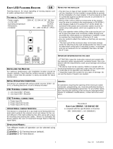
6) Location and Mounting
The location of the unit should be made with due regard to
the area over which both the sounder and beacon warning
signals must be audible and visible. The unit should only be
fixed to services that can carry the weight of the unit.
The unit should be securely bolted to a suitable surface using
the 7mm diameter boltholes in the stainless steel U shaped
mounting bracket (see figure 1). The angle can then be
adjusted in the direction such that its warning signals can be
both heard and seen. This can be achieved by loosening the
two large bracket screws in the side of the unit, which allow
adjustment in steps of 18°. On completion of the installation
the two large bracket adjustment screws on the side of the
unit must be fully tightened to ensure that the unit cannot
move in service.
SAFETY WARNING:
The flashdome guard must not be removed from the unit
at any time.
7) Access to the Flameproof Enclosure
In order to connect the electrical supply cables to the unit it is
necessary to remove the beacon section to gain access to
the flameproof chamber. To achieve this remove the four M6
hexagon socket head screws (see figure 2) and withdraw the
beacon section taking extreme care not to damage the
flameproof joints in the process.
Note the four M6 screws are Class A4-80 stainless steel
and only screws of this category can be used on these
units. It is therefore important that these screws and their
spring washers are kept in a safe place during installation.
On completion of the cable wiring installation the flameproof
joints should be inspected to ensure that they are clean and
that they have not been damaged during installation. Also
check that the earth bonding wire between the two casting
sections is secure and the ‘O’ ring seal is in place. When
replacing the beacon section casting, ensure that it is square
with the sounder section chamber casting before inserting.
Carefully push the beacon section in place allowing time for
the air to be expelled. Only after the beacon section casting is
fully in place should the four M6 Stainless Steel A4-80 cover
bolts and their spring washer be inserted and tightened
down. If the beacon section jams while it is being inserted,
carefully remove it and try again. Never use the cover bolts to
force the beacon section casting into position.
In case of repair, contact the manufacturer for information on
the dimensions of the flameproof joints.
8) Power Supply Selection
It is important that a suitable power supply is used to run the
unit. The power supply selected must have the necessary
capacity to provide the input current to all of the units
connected to the system. The sounder and beacon sections
are both wired to the same power supply.
The following table shows the input current taken by the
sounder section and beacon section of the various units:-
Unit Type Input Sounder Max.
Voltage Current I/P Volts
BExDCTS110-05D 24V DC 265mA 30V
BExDCTS110-05D 12V DC 195mA 15V
BExDCTS110-05D 48V DC 130mA 58V
BExDCTS110-05D 230V AC 56mA 264V
BExDCTS110-05D 115V AC 110mA 126V
Unit Type Input Beacon Max.
Voltage Current I/P Volts
BExDCTS110-05D 24V DC 300mA 30V
BExDCTS110-05D 12V DC 750mA 15V
BExDCTS110-05D 48V DC 180mA 58V
BExDCTS110-05D 230V AC 55mA 264V
BExDCTS110-05D 115V AC 140mA 126V
The above table also shows the maximum voltages at which
the units can be operated.
Sounder Section
The input current to the sounder section will vary according to
the voltage input level and the frequency of the tone selected.
S/S Mounting
Bracket
Sounder
Section
Flashdome
Guard
Plastic Acoustic Horn
(Anti-static Plastic)
Fig 1
Beacon
Section
4 off Cover Screws
External Earth
Terminal
Fig 2

_______________________________________________________________________________________________________________________________
European Safety Systems Ltd. Impress House, Mansell Road, Acton, London W3 7QH [email protected] Tel: +44 (0)208 743 8880
www.e-2-s.com Fax: +44 (0)208 740 4200
Document No. IS 2446-76-P Issue 1 25/02/13 Sheet 3 of 6 Mod No: ACN0012
The current levels shown above are for the 440Hz
Continuous tone @ nominal input voltage. The 24V and 48V
DC units and the 230V and 115V AC units have a switching
voltage regulator circuit and therefore the input current level
will decrease slightly as the input voltage in increased and
will increase slightly as the input voltage is reduced. The 12V
units do not have a voltage regulator and therefore their input
current will increase when the input voltage is increased.
Beacon Section
The input current to the beacon section will vary according to
the voltage input level. The current levels shown above are
for nominal input voltage. The 12V, 24V and 48V DC units
have a converter circuit and therefore the input current level
will decrease slightly as the input voltage is increased and will
increase slightly as the input voltage is reduced.
9) Cable Selection
When selecting the cable size consideration must be given to
the input current that each unit draws (see table above), the
number of units on the line and the length of the cable runs.
The cable size selected must have the necessary capacity to
provide the input current to all of the units connected to the
line.
SAFETY WARNING: If the unit is used at high ambient
temperatures, i.e. over +40ºC, then the cable entry
temperature may exceed +70ºC and therefore suitable heat
resisting cables must be used, with a rated service
temperature of at least 110ºC.
10) Earthing
Both AC and DC units must be connected to a good quality
earth. The units are provided with internal and external
earthing terminals, which are both, located on the beacon
section of the unit (see figures 2 and 3).
When using the external earth terminal a cable crimp lug
must be used. The cable lug should be located between the
two M5 stainless steel flat washers. The M5 stainless steel
spring washer must be fixed between the outer flat washer
and the M5 stainless steel nut to ensure that the cable lug is
secured against loosening and twisting.
The internal earth bonding wire ensures that a good quality
earth is maintained between the sounder section casting and
the beacon section casting.
11) Cable Glands
The BExDCTS110-05D unit has dual cable gland entries
which have an M20 x 1.5 entry thread as standard. Only
cable glands approved for Ex ‘d’ applications can be used,
which must be suitable for the type of cable being used and
also meet the requirements of the Ex ‘d’ flameproof
installation standard EN 60079-14:2008 / IEC60079-14:2007.
When only one cable entry is used the other one must be
closed with an Ex ‘d’ flameproof blanking plug, which must be
suitably approved for the installation requirements.
For combustible dust applications, the cable entry device and
blanking elements shall be in type of explosion protection
increased safety "e" or flameproof enclosure "d" and shall
have an IP 6X rating according to EN60529:1992.
SAFETY WARNING: If the unit is used at high ambient
temperatures, i.e. over +40ºC, then the cable entry
temperature may exceed +70ºC and therefore suitable heat
resisting cable glands must be used, with a rated service
temperature of at least 110ºC.
12) Cable Connections
The combined sounder / beacon unit BExDCTS110-05D has
separate printed circuit boards in the sounder and beacon
sections. The terminals for the incoming power supply and
telephone signal are on the printed circuit board in the
sounder section and the terminals for the beacon are on the
printed circuit board in the beacon section (see figures 4&5
and 6&7). See section 7 of this manual for access to the
enclosure and the wiring diagrams at the end of this manual.
The incoming cables must be wired to the terminals on
the electronics assembly in the sounder and beacon
section of the unit.
POWER CONNECTIONS TO SOUNDER AND BEACON
SECTION
The power input cable should enter the enclosure via one of
the M20 cable entries and be connected to the following
terminals.
The power input (L) AC units or (+ve) DC units is connected
to the telephone board (L/+) terminal (see figures 8 & 9)
The power input (N) AC units or (-ve) DC units is connected
to the beacon board (N) AC or (-ve) DC units terminal (see
figures 8 & 9)
(L & N) AC units (+ve & –ve) DC units in the sounder section
of the unit (see figures 6 and 7).
The telephone signal cable should enter the enclosure via the
other M20 entry and be connected to the telephone terminal
in the sounder section of the units (see figures 6,7 and 8,9)
and wiring diagrams on pages four and five.
A single wire with a cross sectional area of up to 4mm² can
be connected to each terminal way. When connecting wires
to the terminals great care should be taken to dress the wire
so that when the beacon section is inserted into the chamber
the wires do not exert excess pressure on the terminal
blocks. This is particularly important when using cables with
large cross sectional areas such as 2.5mm² and above.
Internal Bonding Wire Terminal
Internal Earth Terminal
2 off M20
Cable Entries
Figure 3

_______________________________________________________________________________________________________________________________
European Safety Systems Ltd. Impress House, Mansell Road, Acton, London W3 7QH [email protected] Tel: +44 (0)208 743 8880
www.e-2-s.com Fax: +44 (0)208 740 4200
Document No. IS 2446-76-P Issue 1 25/02/13 Sheet 4 of 6 Mod No: ACN0012
13) Sounder Tone Selection
The BExDCTS110-05D combined sounder / beacons have
32 different tones that can be selected by the DIP switches
on the sounder pcb (see figures 6 and 7). The tone table on
page five shows the switch positions for the 32 tones.
14) Sounder Volume Control
The BExDCTS110-05D combined sounder / beacon has a
volume control to adjust the output level. To set the required
output level, adjust the potentiometer on the sounder pcb
(see figure 6 & 7). For maximum output level the
potentiometer should be set to the fully clockwise position.
15) Telephone Setting DIP & Continuous or Pulse
Sounder Beacon Operation
The BExDCTS110-05D combined sounder / beacon has a
number of modes of operation. The sounder and beacon can
be set individually to either run continuously or pulsed at the
cadence of the ringing tone.
This is set by setting the DIP switches on the Telephone pcb
(see figures 6 and 7).
The Telephone Selection Table on page six shows the switch
positions 1 - 4 for the country setting and switch 5 for the
beacon continuous or pulse mode and switch 6 for the
sounder continuous or pulse mode. When making any
changes to the country selection, the unit needs to be
de-energised for a minimum of 2 minutes for the changes
to take effect.
When pulse mode of operation is selected the tone pattern
will pulse on and off following the telephone input signal.
Note if pulsed tone operation is selected it is advisable not to
select any of the intermittent tones, such as tone 11.
The beacon will flash at the ringing cadence if pulse is
selected.
L
L
N
N
Figure 4
AC Power
Supply Input
Terminals
BExDCTS110-05D AC Beacon Section
DC Power Supply
Input Terminals
Figure 5
-
-
+
+
BExDCTS110-05D DC Beacon Section
Figure 6
BExDCTS110-05D AC Sounder Section
BExDCTS110-05D DC Sounder
Section
Section
Figure 7
Sounder
tone DIP
Switch
Sounder
Volume Control
TB1 Telephone
Signal
Input Terminals
TB3 Sounder
Mains Supply
Output L
Telephone
Setting DIP
Switch
Sounder Mains Supply
Terminals L and N
TB2 Beacon
Mains Supply
Output L
LLTerminals
L and N
Sounder
tone DIP
Switch
Sounder
Volume Control
TB1 Telephone
Signal
Input Terminals
TB3 Sounder
Mains Supply
Output L
Telephone
Setting DIP
Switch
Sounder Mains Supply
Terminals +ve and -ve
TB2 Beacon
Mains Supply
Output L
LLTerminals
L and N

_______________________________________________________________________________________________________________________________
European Safety Systems Ltd. Impress House, Mansell Road, Acton, London W3 7QH [email protected] Tel: +44 (0)208 743 8880
www.e-2-s.com Fax: +44 (0)208 740 4200
Document No. IS 2446-76-P Issue 1 25/02/13 Sheet 5 of 6 Mod No: ACN0012
TONE SELECTION TABLE Note Switch No. 6 is not used
16) CAUTION! - Ensure correct orientation of
Beacon Housing onto Sounder housing when
closing unit
Please note that due to the tight spacing internally the
Beacon housing can only be closed in one orientation relative
to the Sounder housing, otherwise PCB boards may become
damaged.
The M20 entries on the Beacon housing must be aligned with
the product labels on the side of the Sounder housing (both
M20 entries and labels on the same side).
Tone Selection
DIP Switch
Settings
Stage 1
Frequency Description
1 2 3 4 5
1
Continuous 1000Hz
Toxic gas alarm
0 0 0 0 0
2
Alternating 800/1000Hz at 0.25s
intervals
1 0 0 0 0
3
Slow Whoop 500/1200Hz at 0.3Hz
with 0.5s gap repeated
0 1 0 0 0
4
Sweeping 800/1000 at 1Hz
1 1 0 0 0
5
Continuous at 2400Hz
0 0 1 0 0
6
Sweeping 2400/2900Hz at 7Hz
1 0 1 0 0
7
Sweeping 2400/2900Hz at 1Hz
0 1 1 0 0
8
Siren 500/1200/500Hz at 0.3Hz
1 1 1 0 0
9
Sawtooth 1200/500Hz at 1Hz
0 0 0 1 0
10
Alternating 2400/2900Hz at 2Hz
1 0 0 1 0
11
Intermittent 1000Hz at 0.5Hz General
alarm
0 1 0 1 0
12
Alternating 800/1000Hz at 0.875Hz
1 1 0 1 0
13
Intermittent 2400Hz at 1Hz
0 0 1 1 0
14
Intermittent 800Hz 0.25s on 1s off
1 0 1 1 0
15
Continuous at 800Hz
0 1 1 1 0
16
Intermittent 660Hz 150mS on, 150mS
off
1 1 1 1 0
17
Alternating 544Hz
(100mS)/440Hz(400mS)
0 0 0 0 1
18
Intermittent 660Hz 1.8s on, 1.8s off
1 0 0 0 1
19
1400Hz to 1600Hz sweep up over 1s -
1600Hz to 1400Hz sweep down over
0.5s
0 1 0 0 1
20
Continuous 660Hz
1 1 0 0 1
21
Alternating 554/440Hz at 1Hz
0 0 1 0 1
22
Intermittent 554Hz at 0.875Hz
1 0 1 0 1
23
800Hz pulsing at 2Hz
0 1 1 0 1
24
Sweeping 800/1000Hz at 50Hz
1 1 1 0 1
25
Sweeping 2400/2900Hz at 50Hz
0 0 0 1 1
26
Simulated bell sound
1 0 0 1 1
27
Continuous 554Hz
0 1 0 1 1
28
Continuous 440Hz
1 1 0 1 1
29
Sweeping 800/1000Hz at 7Hz
0 0 1 1 1
30
420Hz repeating 0.625s on, 0.625s off
Australian alert signal
1 0 1 1 1
31
1200/500Hz at 1 Hz
Prepare to abandon platform
0 1 1 1 1
32
Sweeping 500/1200Hz 3.75s on, 0.25s
off 15Hz
1 1 1 1 1
Customer Connection
Power Supply Wires
-ve to Beacon, +ve to
Telephone PCB
BExDCTS110-05D DC Wiring Diagram
BExDCTS110-05D AC Wiring Diagram
Sounder &
Telephone
Section
Beacon Section
Sounder &
Telephone
Section
Customer Connection
Power Supply Wires
N to Beacon, L to
Telephone PCB
Figure 8
Figure 9
Beacon Section

_______________________________________________________________________________________________________________________________
European Safety Systems Ltd. Impress House, Mansell Road, Acton, London W3 7QH [email protected] Tel: +44 (0)208 743 8880
www.e-2-s.com Fax: +44 (0)208 740 4200
Document No. IS 2446-76-P Issue 1 25/02/13 Sheet 6 of 6 Mod No: ACN0012
TELEPHONE DIALING COUNTRY AND
CONTINUOUS OR PULSE SELECTION TABLE
Telephone Selection
Settings
DIP Switch
Settings
DIP Switch
Settings
Dialing Country Setting
1 2 3 4
5 6
Australia
Ireland
New Zealand
Singapore
South Africa
UK
0 0 0 0
Belgium
Canada
Cyprus
Hong Kong
Spain
Turkey
USA
1 0 0 0
Czech Republic
Finland
France
Germany
Greece
Italy
Luxemburg
Netherlands
Norway
Switzerland
0 1 0 0
Austria
Iceland
Portugal
Sweden
1 1 0 0
Denmark
0 0 1 0
Pulse or Continuous Setting
Beacon & Sounder Continuous
0 0
Beacon Continuous, Sounder Pulsed
0 1
Beacon Pulsed, Sounder Continuous
1 0
Beacon & Sounder Pulsed
1 1
/