
1
IMPORTANT:
IMPORTANT:
Go to www.extron.com for the complete
user guide, installation instructions, and
specifications before connecting the
product to the power source.
UCS FT 901 and UCS FR 902 • Setup Guide
This guide provides basic instructions for an experienced technician to install and
congure the Extron UCS 900 Series. The UCS FT 901 and UCS FR 902 extend USB
signals from USB 3.x, 2.0, and 1.1 peripheral devices located up to 492 feet (150 meters)
away to a USB 3.x host computer over multimode ber optic cable, with a SuperSpeed
data transfer rate of up to 5 Gbps. The transmitter features a USB Type-C connector.
The receiver features a built-in active two-port hub that supplies up to 5 V, 1.5 A from
each port to power attached devices.
See the UCS FT 901 and UCS FR 902 User Guide, available at www.extron.com, for more information.
NOTE:
• This product supports USB data ONLY. DisplayPort Alt Mode and Power Delivery are NOT supported.
• The use of a USB 2.0 hub on the UCS FR 902 is not recommended. If a hub is needed in the system, Extron
recommends the use of a USB 3.x hub. Please contact your Extron AE for more details.
Installation
ATTENTION: Installation and service must be performed by authorized personnel only.
ATTENTION : L’installation et l’entretien doivent être effectués uniquement par un technicien qualifié.
Mounting
The UCS FT 901 and UCS FR 902 can be rack mounted, furniture mounted, or placed on a tabletop with the provided rubber feet.
For ZipClip mounting instructions, see the UCS FT 901 and UCS FR 902 User Guide at www.extron.com.
Connecting Cables
WARNING: Fiber optic connectors emit continuous invisible light, which may be harmful to the eyes; use with caution. Do
not look into the fiber optic cable connectors or into the fiber optic cables themselves. Plug the attached dust caps into the
optical transceivers when the fiber cable is unplugged.
ADVERTISSEMENT : Les connecteurs de fibre optique émettent une lumière invisible continue, qui peut être dangereuse
pour les yeux ; à utiliser avec précaution. Ne pas fixer directement les connecteurs optiques ou les câbles fibre optique.
Branchez les protections contre la poussière dans l’ensemble émetteur/récepteur lorsque le câble fibre optique est
débranché.
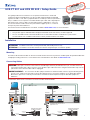
The illustration below shows connections for the UCS FT 901 and UCS FR 902.
POWER
12V
HOST
USB-C
SS 5G
Tx
OUTPUT
Rx
1
24
POWER
12V
1.0A MAX
INPUT
OUTPUTS
1
2
4
PO
WER
12
V
1
.
0
A MAX
INPUT
O
UTPUT
S
POWER
12V
DEVICES INPUT
Tx
1
Rx
2
1.5 A
1.6A MAX
Ground
+12 VDC input
G
External Power Supply
(12 VDC, 2.0 A max.)
Ground all
Devices
Ground
+12 VDC input
G
External Power Supply
(12 VDC, 0.5 A max.)
Ground all
Devices
0.1A MAX
USB
USB Camera
Receiver
USB
Laptop
5
5
5
3
3
3
6
6
6
5
5
5
Transmitter
Multimode Fiber Optic Cable
Compatible with USB 3.x, 2.0, 1.x
peripheral devices
1
1
1
2
2
2
3
3
3
4
4
4
Compatible with USB 3.x
host ports ONLY

2
68-3621-50 Rev. C
05 21
For information on safety guidelines, regulatory compliances, EMI/EMF compatibility, accessibility, and related topics, see the
Extron Safety and Regulatory Compliance Guide on the Extron website.
© 2021 Extron — All rights reserved. www.extron.com
All trademarks mentioned are the property of their respective owners.
Worldwide Headquarters: Extron USA West, 1025 E. Ball Road, Anaheim, CA 92805, 800.633.9876
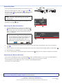
Connecting Power
Power off all devices that will be directly connected to the receiver.
Wire the provided 24 W power supply (see previous page,
1
) to
the receiver 2-pole captive screw connector (
3
), and the provided
6 W power supply (
2
) to the transmitter (see gure at right for
wiring instructions).
NOTE: The UCS FT 901 (transmitter) can also be powered
by the Host device, without the need for the external
power supply.
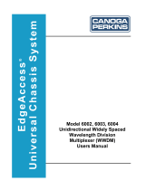
Once a unit receives power, the front panel Power LED (see unit
illustrations to the right,
A
) lights.
Connecting the Host (Transmitter)
1. Connect a USB Type A-to-C (or Type C-to-C) cable from the
Host device to the transmitter HOST port (see previous page,
4
). The HOST LED on the transmitter (see figure at right,
B
)
lights as communication between the transmitter and host
device is established.
NOTE: The transmitter is compatible with and must
be connected to a USB 3.x host ports ONLY. Ensure
that the USB cable used between the USB port of the
Host PC and transmitter input supports USB 3.x.
USB 3.x ports are either blue Type A, Type C, or
labeled with a SuperSpeed trident logo (see below).
®
2. Connect a multimode fiber optic cable from the output port of the transmitter to the input port of the receiver (see previous
page,
5
).
3. Once the cable is connected to both the transmitter and receiver, the front panel LINK LEDs light steadily (see figure above,
C
).
4. Mount the devices, if appropriate.
5. Power on the host device. The transmitter (UCS FT 901) HOST LED (
B
) lights when the computer recognizes the transmitter.
Connecting the Devices (Receiver)
The receiver is compatible and can be connected to USB 3.x, 2.0, & 1.x peripheral devices. Connect up to two USB peripheral
devices to the receiver devices ports (see previous page,
6
). The order of connection does not matter.
The UCS FR 902 (receiver) supplies up to 5 V, 1.5 A to each connected peripheral device.
The system is now ready to operate.
Captive Screw Connector
Tie Wrap
Heat
Shrink
1/8"
(3 mm)
7/8"
(22 mm)
3/16"
(5 mm) Max.
e
UCS FR 902
LINK
STATUS
POWER
12V
--A MAX
DEVICES INPUT
Tx
1
Rx
2
1.5 A
A C
A C
B
UCS FT 901e
LINK
HOST
STATUS
POWER
12V
0.1A MAX
HOST
USB-C
SS 5G
Tx
OUTPUT
Rx
A B C
A B
C
-
 1
1
-
 2
2


Extron electronics UCS 900 Series User manual
- Type
- User manual
- This manual is also suitable for
Ask a question and I''ll find the answer in the document
Finding information in a document is now easier with AI
in other languages
Related papers


Other documents
-
Cisco Systems UCSEZINFRACHSS User manual
-
Extron UCS 601 User guide
-
Cisco N2XX-AQPCI05 Datasheet
-
Cisco UCS-SD800G0KS2-EP= Datasheet
-
-
-
-
-
-
 Continental Automated Buildings Association 6002 User manual
