Page is loading ...

Undercounter
High Temperature
Dishwasher
Installation/Operation Manual
CMA Dishmachines
12700 Knott Street
Garden Grove, CA 92841
Toll Free: 1 (800) 854-6417
Fax: 1 (714) 895-2141
Issue Date: 4.17.09
Manual P/N 0512865 rev. 0
Printed in the USA
For machines beginning with S/N W090217876 and above
Machine Serial No.
Models:
UC65e
UC65e
CMA Dishmachines
12700 Knott Street
Garden Grove, CA 92841
Toll Free: 1- (800) 854-6417
Fax: 1- (714) 895-2141

COPYRIGHT © 2009 All rights reserved Printed in the USA
For future reference, record your dishwasher information in the box below.
Model Number__________________________ Serial Number_______________________
Voltage________________Hertz_____________ Phase__________________
Service Agent __________________________________ Tel:______________________
Parts Distributor _________________________________ Tel:______________________
ATTENTION:
The model no., serial no., voltage, Hz
and phase are needed to identify your
machine and to answer questions.
The machine data plate is located
on the lower front panel.
Please have this information ready
if you call for service assistance.
National Service Department
CMA Dishmachines
12700 Knott Avenue
Garden Grove, CA 92841
Toll-free: 1 (800) 854-6417
Fax: 1 (714) 895-2141

i
Revision History
Revision Revised Serial Number Revision
Date Pages Effectivity Description
4.17.09 All W090217876 Released First Edition
Revision History
• TheRevisionHistorycancontainpartnumberchanges,newinstructions,or
informationthatwasnotavailableatprinttime.
• Wereservetherighttomakechangestotheseinstructionswithoutnoticeandwithout
incurringanyliabilitybymakingthechanges..
• Equipmentownersmayrequestarevisedmanual,atnocharge,bycalling
CMADishmachinesat1(800)854-6417.

ii
Model Description
Model Description
UC65e
Hightemperaturehotwatersanitizingdishwasherwithbuilt-in40°F/22°Criseboosterheater.
208-240VAC/60/1

iii
Model UC65e Undercounter Dishwasher
Revision History...................................................................................................................i
Model Descriptions ..............................................................................................................ii
Installation..............................................................................................1
Receiving ....................................................................1
Electrical Connections ................................................2
Water Connections .....................................................4
Drain Connections ......................................................5
Initial Start-up..........................................................................................6
Booster Fill Switch ......................................................6
Assembly ......................................................8
Chemical Dispensing Pumps ......................................9
Priming ..............................10
Adjusting............................11
Operation ................................................................................................................ 13
Normal Wash Mode ....................................................13
Saf-T-Temp .................................................................14
Cleaning and Maintenance........................................................................15
Cleaning ......................................................................15
Maintenance ...............................................................18
Troubleshooting ..........................................................19
Electrical Schematic.............................................................................................. 21
Timer Chart............................................................................................ 22
Fill/Drain Timer -Theory of Operation......................................................... 23
Table of Contents
Table of Contents

iv
Blank Page
This Page
Intentionally
Left Blank

1
NOTE:
The installation of your dishwasher must be performed by qualied service personnel.
Problems due to improper installation are not covered by the Warranty.
1. Inspect the outside of the dishwasher carton for signs of damage.
2. Remove the carton and inspect the dishwasher for damage.
3. Check for any accessories that may have shipped with your dishwasher.
4. Move the dishwasher near its permanent location.
CAUTION:
Be careful when lifting and moving the dishwasher to prevent damage to the machine.
NOTE:
The installation of the dishwasher must comply with local health codes.
5. Compare the installation site utility connections with the dishwasher utility connections and
make sure that they are the same.
6. The dishwasher can be installed as a free-standing unit or under a built-in counter-top.
The typical counter-top height in most locations is 34" [86cm].
7. Under counter installations should provide storage space for the dishwasher chemical supply
containers. Containers must not be
placed higher than 10" [25cm] above the oor.
8. Chemical supply containers should be placed as
close as close to the machine as possible.
9. Place the dishwasher in its permanent location.
10. The dishwasher has 4 adjustable feet for
leveling.
11. Level the dishwasher front-to-back and
side-to-side.
Installation
Receiving
Counter-top
Wall
3" [8cm] Min.
34"
[86cm]
Min.
Floor

2
Installation
Electrical Connections
WARNING:
Electrocution or serious injury may result when working on
an energized circuit.
Disconnect power at the main breaker or service disconnect
switch before working on the circuit.
Lock-out and tag the breaker to indicate that work is being
performed on the circuit.
The Main Terminal Block (MTB) is located on the left-rear corner
of the electrical panel.
ATTENTION
A qualied electrician must connect the main incoming power to the dishwasher in accordance
with all local codes and regulations or in the absence of local codes in accordance with the
National Electrical Code
Main Terminal Block
VERIFY THE CORRECT VOLTAGE IS SUPPLIED TO THE MACHINE
THE CORRECT SUPPLY VOLTAGE IS 115/208-240VAC/60/1.
(See the diagram on next page.)

3
1. Refer to the connection diagram on the preceding page and the photo below:
2. Machines require a 3-wire plus ground supply which includes a current carrying neutral.
3. Power connections are made at the Main Terminal Block (MTB).
4. The MTB is located on the left-rear corner of the electrical panel behind the front access panel.
(See the illustration on the previous page.)
Installation
Electrical Connections
1. Remove the lower front access panel of the dishwasher.
2. Locate the electrical mounting panel on the right-side of the machine.
Remove the retaining nut at the top of the panel that holds the panel in place.
3. Lower the panel and pull it forward to gain access the MTB.
4. Feed the power cable through the cable hole located
on the right side, as viewed from the front of the machine,
into the interior of the machine.
5. Make sure the cable passes through the cable mounting
bracket located near the front-center of the
base and secure the cable with a cable connector.
6. Connect the ground wire to the base of the dishwasher
with the ground screw provided next to the
cable mounting bracket.
7. Feed the remaining cable wires to the Main Terminal
Block and connect according to the connection
diagram to the right.
To Connect Main Power to the Dishwasher:
NOTE:
Provide a 3 foot service loop in the power cable at the back of the dishwasher for service.
L1 L2 N
208-240
VAC
115VAC
GRD
SINGLE PHASE POWER CONNECTION
115/208-240VAC/60/1
HOW TO CONNECT POWER
1. Check the data plate on the front of the
dishwasher for the voltage of the machine.
2. Remove the lower-front access panel.
3. Lower the electrical component bracket.
4. Feed the power cable from the rear of the
dishwasher to the center of the machine
and through the cable bracket.
5. Connect the ground wire to the base of the
dishwasher using the ground screw located
near the bracket.
6. Feed the power leads to the terminal block.
7. Connect L1, L2 and a currrect-carrying
neutral to the Main Terminal Block.
8. Main Power connections are complete.
To Main Terminal Block
From Rear of Machine
L1
L2
N
GRD
Cable Bracket
Route the supply cable through the cable bracket.

4
Installation
Water Connections
1. All models have a 6 ft. exible hot water ll hose with a 3/4" GHT connector.
2. A 1/2" or larger main incoming supply line should be installed to the dishwasher.
3. A 1/2" or larger shut-off valve should be installed in the water supply line as close to the
dishwasher as possible for service.
4. The hot water supply must provide a minimum of 140°F/60°C, measured at the dishwasher for
the 40°F/ 22°C rise booster.
5. For the 70°F/39°C rise booster the hot water supply must provide a minimum of 110°F/43°C
measured at the dishwasher.
Note
Plumbing connections must comply with national, local plumbing and sanitary codes.
IMPORTANT
Make sure that the exible water supply and drain hoses are not kinked.

5
Installation
1. The dishwasher has a 6ft. 3/4" I.D. drain hose. The maximum drain height
connection must not exceed 3 ft.[9 m].
The recommended drain height is 17" [.4 m] or less above the oor.
2. The drain hose is secured to the rear of the machine by a clamp to maintain a
goose-neck bend in the drain hose.
DO NOT REMOVE THE DRAIN HOSE RETAINING CLAMP.
DO NOT STRETCH THE DRAIN HOSE.
3. Install the drain hose to a "WYE" drain tting. Connection to a "TEE" tting will
prevent the dishwasher from draining completely.
4. The maximum drain ow is 8 U.S. gpm/7 Imp. gpm/30 L.P.M.
5. Make sure the drain hose does not kink. Kinks will prevent the dishwasher
from draining completely, and the dishwasher will overow out the front door.
NOTE: DO NOT CONNECT THE DRAIN HOSE TO A DISPOSER.
THE DISHWASHER WILL NOT DRAIN CORRECTLY.
Drain Connections
ATTENTION
Do not connect the drain hose to a disposer. The dishwasher will not drain correctly.
The dishwasher flexible drain hose
must be connected to a WYE fitting.
Do not connect the dishwasher
flexible drain hose to a TEE fitting.

6
Initial Start-Up
Booster Fill Switch
The booster heater is lled using the Booster Fill Switch. It is located behind the lower front access panel
and on the left-side of the bracket that holds the chemical dispensing pumps (see the photos below).
Fill the booster heater:
1. Make sure that the dishwasher power switch is OFF.
2. Remove the lower front access panel.
3. Locate the booster ll switch. It is in the left-center of the electrical component panel.
4. Make sure the Booster Fill Switch is in the middle position, (OFF).
5. Turn the water supply and the main power supply on.
DO NOT TURN THE DISHWASHER POWER SWITCH ON.
Note:
The dishwasher contains a built-in booster heater that was drained prior to shipment
and must be lled with water before operating the dishwasher.
Filling the Booster
A) Identify the booster ll switch.
ON
OFF
BOOSTER
FILL
RINSE
TEMPERATURE
WASH
Booster Fill Switch
A
ATTENTION
VERIFY THE CORRECT VOLTAGE IS SUPPLIED TO THE MACHINE
THE CORRECT SUPPLY VOLTAGE IS 115/208-240VAC/60/1.
(Refer to the diagram on page 3.)

7
Initial Start-Up
Filling the Booster (continued)
B) Press and hold the Booster Fill Switch down to the BOOSTER FILL
position until you hear the water spraying inside the dishwasher wash tank,
then release the switch.
C) Push the switch up to the ON position and release.
The booster tank is lled.
ON
OFF
BOOSTER
FILL
RINSE
TEMPERATURE
WASH
B
ON
OFF
BOOSTER
FILL
RINSE
TEMPERATURE
WASH
C

8
Initial Start-up
Check List
1. Remove any protective lm from dishwasher. Check the interior for foreign material.
2. Make sure that the dishwasher is permanently located.
3. Make sure that all utility connections are complete.
4. Make sure that the exible drain hose and the hot water ll hose are not kinked.
5. Make sure that the chemical supply containers are full and that the chemical pick-up tubes
are installed in the proper containers.
6. Make sure that the sump lter is in place.
7. Make sure that the overow tube is installed and rmly seated in the sump.
8. Make sure that the spray arms are in place and that they spin freely.
9. Fully close the dishwasher door.
10. Turn hot water supply on and check for leaks in the main water supply piping connected
to the dishwasher.
Install the scrap screen, overow tube, and spray arms.
Make sure the spray arms turn freely.
IMPORTANT
During the initial fill, the flowing pressure of the incoming water
is set to 20-22 PSI.

9
1. The dishwasher is equipped with a built-in detergent dispensing pump and rinse-aid dispensing
pump. (See the photographs below.)
2. The pumps are located on the lower panel behind the lower-front access panel.
3. Each pump is equipped with 6 feet [1.8 m] of pick-up supply tubing, a stiffener tube, and a strainer.
4. A red label marked DETERGENT is attached to the detergent pump inlet tubing.
5. A blue label marked RINSE-AID is attached to the rinse-aid pump inlet tubing.
6. The detergent enters the wash tank compartment through a tting at the right rear of the wash
compartment (see the illustration on the next page).
7. The detergent supply should be a non-chlorinated liquid detergent.
8. The rinse-aid enters the nal rinse piping through a tting located on the upper-left rear side of the
dishwasher. The tting is located near the vacuum breaker (see the illustration on the next page).
Initial Start-up
ATTENTION
Contact a local chemical supplier for detergent and rinse-aid chemicals. The detergent should be a
non-chlorinated liquid detergent. The chemical dispensing pumps are adjusted by the chemical supplier.
Chemical Dispensing Pumps
The dispensing pumps are located behind the
lower-front access panel.
A stiffener tube, strainer and pick-up
tubing are supplied with the built-in
detergent and rinse-aid pumps.
RINSE
TEMPERATURE
WASH
ON
OFF
BOOSTER
FILL
Detergent
Pump
Rinse-aid
Pump
9. The chemical supplier will choose the appropriate liquid rinse-aid.
10. Your chemical supplier should adjust the dispensers for the supplied product.
11. Place the chemical supply containers as close to the dishwasher as possible.
12. Do not elevate the chemical containers above the nished oor.

10
Initial Start-up
Chemical Dispensing Pumps (continued)
Detergent enters the wash tank compartment through a
fitting on the rear wall of the wash tank compartment.
The rinse-aid enters the nal rinse piping at the top-rear of
the dishwasher near the vacuum breaker.
Detergent
Injection Point
Rinse-aid
Injection
Point
The illustrations below show the location of the detergent and the rinse-aid injection points.
Chemical Injection Points

11
1. Make sure the chemical containers are full and the correct pick-up tubes are in the containers.
2. Turn the dishwasher power switch ON. The switch will illuminate and the dishwasher will ll with
water.
3. Once the ll is complete, open the dishwasher door, then push and hold the prime push button UP
to the DET (detergent) position until detergent is observed entering at the right-rear of the wash
tank compartment.
4. Push and hold the prime push button DOWN to the R/A (rinse-aid) position for 30-seconds.
Release the push button.
5. Close the door.
Initial Start-up
POWERSTARTDRAINEXT. WASH
OFFON
PRIME
DET
R/A
Chemical Dispenser Prime Switch
The chemical dispensing pumps must be primed before the dishwasher is operated. A 2-position PRIME
switch is located on the front control panel to do this. The Detergent dispensing pump is primed when
the Prime switch is pushed UP to the DET position. The Rinse-aid dispensing pump is primed when the
Prime switch is pushed DOWN to the R/A position (see below).
Priming the Chemical Dispensing Pumps
Chemical Dispensing Pumps

12
Initial Start-up
Chemical Dispensing Pumps
1. Remove the lower-front access panel. The timer assembly is located on the right-side of the
electrical component panel.
2. Make sure the dishwasher power is OFF.
3. The detergent timer cam has 2 halves. Hold the stationary right-half of the cam and turn the
left-half of the cam counter-clockwise to increase the amount of detergent that is dispensed.
Turn the left-half clockwise to decrease the detergent dispensed.
4. The rinse-aid timer cam has 2 halves. Hold the stationary left-half of the cam and turn the right-half
of the cam counter-clockwise to decrease the amount of rinse-aid that is dispensed.
Turn the right-half clockwise to increase the amount of rinse-aid dispensed.
RINSE
AID
PUMP
EXTEND
WASH
SAFE-T
TEMP
DET.
PUMP
RINSE
VALVE
DRAIN
PUMP
WASH
PUMP
HOMING
CAM
D
E
T
E
R
G
E
N
T
R
I
N
S
E
A
I
D
-
+
-
+
CCW
CW
Adjusting the Chemical Dispenser Pumps
The amount of detergent and rinse-aid that are dispensed during the dishwasher cycle are controlled by
adjustable cams on the timer assembly. Variables such as the type of chemicals used and the hardness
of the water supply often require that the timer cam settings must be changed. It is recommended that
the chemical supplier make these adjustments.
(Refer to the illustration below).
Note:
Only the Detergent and the Rinse-aid cams are adjustable. Do not attempt to adjust any other timer cam.
To adjust the chemical dispensing pump timer cams:

13
Operation
Follow the instructions below to operate the dishwasher in a Normal Wash Mode. A Safe-T-Temp feature
holds the dishwasher in a wash mode if the booster heater temperature is below 180ºF/82ºC.
Normal Wash Mode
1. Turn the main power on at the main circuit breaker.
2. Install the sump lter, overow tube and spray arms.
3. Make sure the exible drain hose and the exible ll hose are not kinked,
then turn the water supply on.
4. Close the dishwasher front door.
5. Push the dishwasher Power Switch to the ON position.The power switch will illuminate and the
machine will ll with water.
6. Check the pressure gauge as the machine lls and make sure the incoming water pressure is
between 20-22 psi.
7. Wait 15-minutes for the WASH temperature gauge to indicate a minimum of 150ºF/66ºC.
8. Load soiled wares into the dish rack. Place plates, glasses, cups and bowls in a peg rack.
Place utensils in a single layer in a flat-bottom rack. Place pots and pans in a flat-bottom rack.
Do not overload the dish racks.
9. Slide 1 dish rack into the wash compartment making sure that wares do not interfere with the
rotating spray arms. Do not wash more than 1 dish rack at a time.
10. Close the front door fully, then press and hold the START BUTTON for 1-second. The green
in-cycle light will illuminate and the wash cycle will begin. The wash cycle time runs for
approximately 1-1/2 minutes. (continued on next page)
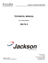
Final Rinse
Pressure
Wash
Temperature
Final Rinse
Temperature
WINSTON-SALEM,NC
CHAMPION INDUSTRIES, INC.
10
0
30
20
PSI
60
50
40
0
20
40
60
80
100
120
140
160
180
200
220
100
80
60
40
20
0
20
40
60
80
100
120
140
160
180
200
220
100
80
60
40
20
20-22 PSI
150°F/66°C
180-195°F
82-91°C
The pressure and temperature gauges are located on the lower-left corner
of the lower-front access panel.
ATTENTION
At the beginning of the day, run 2 empty cycles before checking the final rinse
operating temperature. The first cycle will take longer than normal because the
water temperature in the booster is low.

14
Extended Wash Mode
The Extended Wash Mode is used to wash heavily soiled items such as pots, pans and other wares that
require more washing time than the standard 100-second Normal Wash Mode.
The dishwasher will remain in the Extended Wash Mode until the operator exits the mode.
1. Load a dish rack into the dishwasher, close the door.
2. Press and hold the START button for 1-second then release.
3. The green in-cycle light will illuminate and the dishwasher will begin a normal wash cycle.
4. Press the EXT WASH button to place the dishwasher in the Extended Wash Mode.
5. The green extended wash light will illuminate indicating that the machine is in the
Extended Wash Mode.
6. The dishwasher will continue to wash until the operator presses the EXT WASH button again.
7. Press the EXT WASH button. The green extended wash light will go out indicating that
the dishwasher has returned to the Normal Wash Mode.
8. The dishwasher will nish the wash cycle and perform a nal rinse of the wares.
Operation
The nal rinse water temperature must be a minimum of 180ºF/82ºC during the final rinse cycle to ensure that all
wares are sanitized. If for any reason, the hot water temperature in the booster tank cannot provide this temperature,
the dishwasher will enter a Safe-T-Temp Mode of operation and extend the cycle time.
The Safe-T-Temp changes the Normal Operation Mode as described below:
1. The Safe-T-Temp constantly monitors the water temperature inside nal rinse booster.
2. If the temperature inside the booster heater falls below 180ºF/82ºC then the Safe-T-Temp
will extend the wash cycle time until the booster heater water temperature reaches the proper
temperature.
3. The in-cycle light will remain illuminated during the Safe-T-Temp Mode.
4. The RINSE water temperature gauge must be monitored to ensure that a minimum of
180ºF/82ºC is maintained during the rinse cycle.
5. The temperature range for the final rinse water is180-195ºF/82-91ºC.
6. An extraordinarily long wash cycle may indicate a low incoming water temperature or a
problem with the booster heater operation.
DO NOT REMOVE WARES UNTIL THE FINAL RINSE CYCLE HAS
SANITIZED THE WARES AND THE GREEN CYCLE LIGHT GOES OUT.
Safe-T-Temp Mode
Normal Wash Mode (continued)
11. Opening the door when the dishwasher is in-cycle will stop the dishwasher. The cycle will resume
automatically when the dishwasher door is closed fully.
12. The nal rinse cycle begins at the end of the wash cycle and runs for approximately 15-seconds Check the
RINSE temperature gauge during the nal rinse and make sure that it indicates a minimum of 180ºF/82ºC.
The acceptable range of operation is180-195ºF/82-91ºC.
13. At the end of the rinse cycle, the in-cycle light will go out. Open the door and remove the clean
rack of wares. Repeat steps 8-12 for additional dish racks.
14. Refer to the Cleaning Instructions, "After Each Meal Period or every 8 Hours of Operation", on
page 15 for the procedures to drain and clean the dishwasher.
/