Page is loading ...

Installation Manual for the
SINGLE Gate Operator System
FOR PROFESSIONAL INSTALLATION ONLY!
WARNING!
This equipment is similar to other gate or door equipment and meets or exceeds
Underwriters Laboratory Standard 325 (UL 325). However, gate equipment has
hazards associated with its use and therefore by installing this product the installer
and user accept full responsibility for following and noting the installation and
safety instructions. Failure to follow installation and safety instructions can result
in hazards developing due to improper assembly. You agree to properly install this
product and that if you fail to do so Gates That Open, LLC, (“GTO”) shall in no event
be liable for direct, indirect, incidental, special or consequential damages or loss of
prots whether based in contract tort or any other legal theory during the course
of the warranty or at any time thereafter. The installer and/or user agree to assume
responsibility for all liability and use of this product releasing Gates That Open, LLC,
from any and all liability. If you are not in agreement with this disclaimer or do not
feel capable of properly following all installation and safety instructions you may
return this product for full replacement value.
READ ALL INSTRUCTIONS CAREFULLY AND COMPLETELY before attempting to
install and use this automatic gate operator. This gate operator produces a high level
of force. Stay clear of the unit while it is operating and exercise caution at all times.
All automatic gate operators are intended for use on vehicular gates only.
This product meets and exceeds the requirements of UL 325, the standard which
regulates gate operator safety, as established and made eective March 1, 2000, by
Underwriters Laboratories Inc.
For more information on the GTO/ACCESS SYSTEMS full line of automatic gate
operators and access controls visit our website at www.gtoaccess.com.
©2010 Gates That Open, LLC Printed in China for Gates That Open, LLC. R4000 INST 091610
, LLC
®
4000XL
PROFESSIONAL RESIDENTIAL
ACCESS
SYSTEMS

Class Rating
The GTO 4000XL Gate Operator is intended for use with vehicular swing gates. The operator can be used in Class I,
Class II, Class III and Class IV applications.
Vehicular Gate Operator Class Categories:
Residential Vehicular Gate Operator—Class I: A vehicular gate operator (or system) intended for use in a home of
one-to-four single family dwelling, or a garage or parking area associated therewith.
Commercial/General Access Vehicular Gate Operator—Class II: A vehicular gate operator (or system) intended for
use in a commercial location or building such as a multifamily housing unit (ve or more single family units), hotel,
garages, retail store, or other building servicing the general public.
Industrial/Limited Access Vehicular Gate Operator–Class III: A vehicular gate operator (or system) intended for use in
an industrial location or building such as a factory or loading dock area or other locations not intended to service the
general public.
Restricted Access Vehicular Gate Operator–Class IV: A vehicular gate operator (or system) intended for use in
a guarded industrial location or building such as an airport security area or other restricted access locations not
servicing the general public, in which unauthorized access is prevented via supervision by security personnel.
Converting Metric Units to English Equivalents
When You Know Multiply By To Find Symbol
centimeters 0.3937 inches in. (or ")
meters 3.2808 feet ft. (or ')
kilograms 2.2046 pounds lb. (or #)
Converting English Units to Metric Equivalents
When You Know Multiply By To Find Symbol
inches 2.5400 centimeters cm
feet 0.3048 meters m
pounds 0.4535 kilograms kg
Converting Temperature
deg. Celsius (°C x 1.8) + 32 deg. Fahrenheit °F
deg. Fahrenheit (°F-32) ÷ 1.8 deg. Celsius °C
Serial Number: ___________________________________ Date of Purchase: ________________
Place of Purchase: ___________________________________________________________________
Please record the following information product serial number (located on right side of control box), be sure to
keep all receipts for proof of purchase. Refer to this information when calling GTO for service or assistance
with your automatic gate opener.
FOR YOUR RECORDS

Table of Contents
Class Rating ......................................................................................................................inside cover
Please Read This First ..........................................................................................................................ii
Important Safety Instructions........................................................................................................ iii
Technical Specications .................................................................................................................... 1
Before You Begin... .............................................................................................................................. 2
Determine Charging Option for Battery: Transformer OR Solar ................................. 2
Solar Panel and Gate Activity Chart ....................................................................................... 2
Check Direction of Gate Swing ................................................................................................ 3
Prepare the Gate ........................................................................................................................... 3
4000XL Parts List ........................................................................................................................... 4
Tools Needed .................................................................................................................................. 5
Materials You may Need for the Installation: ..................................................................... 5
Installation Overview .................................................................................................................. 6
Install the Operator ............................................................................................................................ 6
Install the Post Bracket Assembly ........................................................................................... 6
Check Clearance ............................................................................................................................ 8
Install Gate Bracket ....................................................................................................................... 9
Attach Operator ............................................................................................................................. 9
Install Closed Position Stop Plate ..........................................................................................10
Mount the Control Box and Receiver ...................................................................................11
Connect Operator Power Cable .............................................................................................12
Connect the Transformer .........................................................................................................13
Connect Battery ...........................................................................................................................14
Program Control Board ...................................................................................................................15
Set the Closed Position Limit (for Pull-To-Open Applications) ...................................15
Adjust the Stall Force Setting .................................................................................................16
Set Auto Close Time ...................................................................................................................17
Program Your Personal Transmitter Setting ......................................................................17
Control Board Settings .............................................................................................................. 18
Connnecting Accesories ................................................................................................................. 19
Wiring Accesories ........................................................................................................................20
Connecting Other Auxiliary Devices (Sirens, Lights, etc.) .............................................20
Push-To-Open Installation
.............................................................................................................21
Setting the Open Position Limit (Push-To-Open Installations) ...................................22
Column Installation ..........................................................................................................................23
Troubleshooting Guide ................................................................................................................... 24
Voltage Ratings ............................................................................................................................ 25
Repair Service ...............................................................................................................................26
Accessories
..........................................................................................................................................27

ii GTO 4000XL Instruction Manual © 091610
Thank you for purchasing a GTO/ACCESS SYSTEMS 4000XL. When correctly installed and properly used,
your 4000XL operator will give you many years of reliable service. Please read the following information
to ensure you have the correct system for your particular needs. This manual will enable you to properly
install your 4000XL Automatic Gate Operator.
The 4000XL operator is designed for installation on a pull-to-open single leaf gate. The gate must not
exceed 16 feet in length nor weigh more than 650 pounds* (please see Technical Specications on page
1). The 4000XL operator can be used on vinyl, aluminum, chain link, farm tube, and wrought iron gates.
Use on solid (wood) gates is not recommended. Solid surface gates have a high resistance to the wind.
If the wind is strong enough, the operator will obstruct, stop, and blow fuses.
*NOTE: By purchasing and installing the HBP4XL Bracket Set, the 4000XL can accommodate gates that
are 20 feet in length and weigh up to 1000 pounds. The 4000XL can be installed on a push-to-open gate
with the addition of the push-to-open bracket
[R4388].
The 4000XL operator accommodates extra transmitters, digital keypads, solar panels, push buttons,
automatic gate locks, and other access control products. These optional accessories are noted with the
symbol.
The 4000XL operator features adjustable stall force. This safety feature makes the gate stop and reverse
direction within two seconds when it comes in contact with an obstruction. The “MIN” setting means the
gate will exert the minimum force on an obstruction before it stops and reverses direction.
The 4000XL operator also has an adjustable auto-close feature. It can be set to remain open from 3 to
120 seconds before automatically closing. Pressing the transmitter button at any time after the gate fully
opens will cause it to close immediately. “OFF” is the factory setting; meaning the gate will stay open until
you press the transmitter button (or keypad, etc.) again.
Please call GTO at (800) 543-GATE [4283] or (850) 575-0176 for more information about our GTO/ACCESS
SYSTEMS professional line of gate operators and accessories. Our Sales Department will be glad to give
you the name and phone number of a GTO/ACCESS SYSTEMS dealer near you.
BEFORE YOU BEGIN TO INSTALL YOUR AUTOMATIC GATE OPERATOR:
Read these instructions carefully and completely to become familiar with all parts and installation
steps. You must read the installation manual for detailed instructions on gate operator safety
and proper use of the gate operator.
24/7 Troubleshooting Wizard: http://support.gtoinc.com
Please Read This First
, LLC
®
GTO Accessories are noted with this symbol in this Installation
Manual. Information about accessories can be found on page 27
and at www.gtoaccess.com.

GTO 4000XL Instruction Manual © 091610 iii
IMPORTANT SAFETY INSTRUCTIONS
Because automatic gate operators produce high levels of force, consumers need to know the potential
hazards associated with improperly designed, installed, and maintained automated gate operator
systems. Keep in mind that the gate operator is just one component of the total gate operating system.
Each component must work in unison to provide the consumer with convenience, security, and safety.
This manual contains various safety precautions and warnings for the consumer. Because there are
many possible applications of the gate operator, the safety precautions and warnings contained in
this manual cannot be completely exhaustive in nature. They do, however, provide an overview of the
safe design, installation, and use of this product. CAREFULLY READ AND FOLLOW ALL SAFETY
PRECAUTIONS, WARNINGS, AND INSTALLATION INSTRUCTIONS TO ENSURE THE SAFE
SYSTEM DESIGN, INSTALLATION, AND USE OF THIS PRODUCT.
Precautions and warnings in this manual are identified with this
warning symbol. The symbol
identifies conditions that can result in damage to the operator or its components, serious injury, or
death.
Because GTO automatic gate operators are only part of the total gate operating system, it is the
responsibility of the installer/consumer to ensure that the total system is safe for its intended
use.
How To Manually Open and Close the Gate:
CAUTION: The gate can be opened and closed manually when the operator is disconnected.
ONLY disconnect the operator when the operator power switch is OFF and the gate is NOT moving.
Disconnecting the Operator
1. Turn operator power switch (Control Box) OFF.
2. Remove hairpin clip, clevis pin, and bushing from both the front and
rear mounting points.
3. Remove the operator from the mount.
CAUTION: Because the GTO gate operator is battery powered,
disconnect the operator ONLY when the power switch on the contol
box is turned OFF. Unplugging the transformer does not turn power
to the operator OFF.
NOTE: Substitute a Pin Lock
[FM345] for the clevis pin on the front
mount of the gate operator to prevent unauthorized removal of the
operator from the gate.
Clevis Pin
Hairpin Clip
Gate Bracket
Front Mount
Bushing

iv GTO 4000XL Instruction Manual © 091610
IMPORTANT SAFETY INSTRUCTIONS
For The Consumer
WARNING: To reduce the risk of injury or death:
1. READ AND FOLLOW ALL INSTRUCTIONS. Failure to meet the requirements set forth in the instruction manual
could cause severe injury or death, for which the manufacturer cannot be held responsible.
2. When designing a system that will be entered from a highway or main thoroughfare, make sure the system is placed
far enough from the road to prevent traffic congestion.
3. The gate must be installed in a location that provides adequate clearance between it and adjacent structures when
opening and closing to reduce the risk of entrapment. Swinging gates must not open into public access areas.
4. The gate and gate operator installation must comply with any applicable local codes.
I. Before Installation
1. Verify this operator is proper for the type and size of gate, its frequency of use, and the proper class rating.
2. Make sure the gate has been properly installed and swings freely in both directions. Repair or replace all worn or
damaged gate hardware prior to installation. A freely moving gate will require less force to operate and will enhance
the performance of the operator and safety devices used with the system.
3. Review the operation of the system to become familiar with its safety features. Understand how to disconnect the
operator for manual gate operation (page iii).
4. This gate operator is intended for vehicular gates ONLY. A separate entrance or gate must be installed for
pedestrian use (page vi).
5. Always keep people and objects away from the gate and its area of travel. NO ONE SHOULD CROSS THE PATH
OF A MOVING GATE.
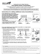
6. Pay close attention to the diagram below and be aware of these areas at all times.
Entrapment Zones for a proper Pull-To-Open installation:
Zone 1 – leading edge of the gate and post.
Zone 2 – between the gate and the gate post.
Zone 3 – the path of the gate.
Zone 4 – the space between the gate in the open position and any object such as a wall, fence, etc.
Zone 5 – pinch points between the operator and gate.
Gate in the
Open Position
ZONE 2
ZONE 3
ZONE 4
ZONE 5
Driveway
ZONE 1

GTO 4000XL Instruction Manual © 091610 v
IMPORTANT SAFETY INSTRUCTIONS
II. During Installation
1. Install the gate operator on the inside of the property and fence line. DO NOT install an operator on the outside of
the gate where the public has access to it.
2. Be careful with moving parts and avoid close proximity to areas where fingers or hands could be pinched.
3. Devices such as contact sensors (safety edges) and non contact sensors (photo beams) provide
additional protection against entrapment.
4. If push buttons or keypads are installed, they should be within sight of the gate, yet located at least 10 feet from any
moving part of the gate (see diagram below). Never install any control device where a user will be tempted to
reach through the gate to activate the gate operator.
5. Do not activate your gate operator unless you can see it and can determine that its area of travel is clear of people,
pets, or other obstructions. Watch the gate through its entire movement.
6. Secure outdoor or easily accessed gate operator controls in order to prohibit unauthorized use of the gate.
III. After Installation
1. Attach the warning signs (included) to each side of the gate to alert the public of auto matic gate operation. It
is your responsibility to post warning signs on both sides of your gate. If any of these signs or warning decals
become damaged, illegible or missing, replace them immediately. Contact GTO for free replacements.
2. The gate is automatic and could move at any time, posing a serious risk of entrapment. No one should be in
contact with an activated gate when it is moving or stationary.
3. Do not attempt to drive into the gate area while the gate is moving; wait until the gate comes to a complete stop.
4. Do not attempt to “beat the gate” (drive through) while the gate is closing. This is extremely dangerous.
5. Do not allow children or pets near your gate. Never let children operate or play with gate controls. Keep ALL
gate controls away from children and unauthorized users; store controls where children and unauthorized users do
not have access to them.
6. KEEP GATE AND GATE Operator PROPERLY MAINTAINED. Always turn power to operator OFF before
performing any maintenance. Regularly grease the gate hinges. Clean the push-pull tube with a soft, dry cloth and
apply silicone spray to it at least once per month.
Moving Gate
Area
Driveway
10'
10'
10'
10'
NEVER INSTALL
any control device
within gray area

vi GTO 4000XL Instruction Manual © 091610
IMPORTANT SAFETY INSTRUCTIONS
7. To operate this equipment safely, YOU must know how to disconnect the operator for manual gate operation (page
iii). If you have read the instructions and still do not understand how to disconnect the operator, contact the GTO
Service Department.
8. Disconnect the operator ONLY when the power is TURNED OFF and the gate is NOT moving.
9. Make arrangements with local fire and law enforcement for emergency access.
10. Distribute and discuss copies of the IMPORTANT SAFETY INSTRUCTIONS section of this manual with all
persons authorized to use your gate.
11. IMPORTANT: Save these safety instructions. Make sure everyone who is using or will be around the gate
and gate operator are aware of the dangers associated with automated gates. In the event you sell the
property with the gate operator or sell the gate operator, provide a copy of these safety instructions to
the new owner.
Should you lose or misplace this manual, a copy can be obtained by downloading one from the GTO web site
(www.gtoaccess.com), by contacting Gates That Open, LLC., at 3121 Hartsfield Road, Tallahassee, Florida
32303 or by calling 1-800-543-4283 and requesting a duplicate copy. One will be provided to you free of
charge.
Required Safety Precautions for Gates
Install Warning Signs
Warning signs alert people of automatic gate operation and are required when installing the GTO Gate Operator. The
Warning Signs included must be installed on both sides of each gate. Furthermore, a walk-through gate must be installed
for pedestrian traffic. We recommend using the GTO Bulldog Pedestrian Gate Lock [FM145] for controlled access.
Entrapment Protection
GTO’s inherent obstruction settings, even when properly adjusted, may not be sensitive enough to prevent bodily
injury in some circumstances. For this reason, safety devices such as safety edge sensors (or photoelectric sensors),
which stop and reverse gate direction upon sensing an obstruction, are suggested for enhanced protection against
entrapment.
Warning Sign
Pedestrian Gate
GTO Bulldog Pedestrian
Gate Lock
Vehicular Gate
Contact Sensor
(recommended, not included)
Contact Sensor
(recommended, not included)
Contact Sensor
(recommended, not included)
(recommended, not included)
Photo Beam
(recommended, not included)
Photo Beam
(recommended, not included)

GTO 4000XL Instruction Manual © 091610 vii
IMPORTANT SAFETY INSTRUCTIONS
Secondary Means of Protection Against Entrapment
As specified by Gate Operator Safety Standard, UL 325 (30A.1.1), automatic gate operators shall have an inherent
entrapment sensing system, and shall have provisions for, or be supplied with, at least one independent secondary
means to protect against entrapment. The 4000XL utilizes Type A, an inherent (i.e., built-in) entrapment sensing system
as the primary type of entrapment protection. Also, the 4000XL has provisions for the connection of Type B1 or B2
protection to be used as the secondary type of entrapment protection, if desired.
1. For gate operators utilizing a non-contact sensor (e.g., photo-electric sensor– Type B1) in accordance with UL 325
(51.8.4 [h]):
A. Refer to the sensor manufacturer’s instructions on the placement of non-contact sensors for each type of
application.
B. Care shall be exercised to reduce the risk of nuisance tripping, such as when a vehicle trips the sensor while the
gate is still moving.
C. One or more non-contact sensors shall be located where the risk of entrapment or obstruction exists, such as the
perimeter reachable by a moving gate or barrier.
2. For gate operators utilizing a contact sensor (e.g., safety edge sensor– Type B2) in accordance with UL 325 (51.8.4
[i]):
A. One or more contact sensors shall be located at the leading edge, bottom edge, and post edge, both inside and
outside of a vehicular swing gate system.
B. A hard wired contact sensor shall be located and its wiring arranged so that the communication between the
sensor and the gate operator is not subjected to mechanical damage.
C. A wireless contact sensor such as one that transmits radio frequency (RF) signals to the gate operator for
entrapment protection functions shall be located where the transmission of the signals are not obstructed or
impeded by building structures, natural landscaping or similar obstruction. A wireless contact sensor shall
function under the intended end-use conditions.
You may want to consider adding photo beams to your installation. GTO Photo Beams [R4222] provide a “non contact”
means of entrapment protection.
ENTRAPMENT ALARM (UL 325; 30A.1.1A)
The 4000XL Gate Operator is designed to stop and reverse within 2 seconds when the gate comes in contact with
an obstruction. Additionally, these operators are equipped with an audio entrapment alarm which will activate if the
unit obstructs twice while opening or closing. This alarm will sound for a period of 5 minutes, or until the operator
receives an intended signal from a hard wired entry/exit source (e.g. push button control or keypad) and the gate
returns to a fully open or fully closed position. Turning the power switch on the control box OFF and back ON will also
deactivate the alarm. Wireless controls such as transmitters and wireless keypads will not deactivate the alarm.
Vehicular Gate
Leading Edge Contact Sensor
on both sides of the gate
Bottom Edge Contact Sensor
on both sides of the gate
Post Edge Contact Sensor
on both sides of the gate
Photo Beam
Photo Beam

viii GTO 4000XL Instruction Manual © 091610
IMPORTANT SAFETY INSTRUCTIONS
!
Warning signs (2 enclosed) to be installed on each side
of the gate (3–5 feet above the bottom of the gate).
Maximum Gate: 650 lb. (294.8 kg); 16 ft. (4.9 m)
Voltage: 12 Vdc; Frequency: 0 Hz; Power: 60 W
Class I, II, III and IV Vehicular Swing Gate Operator.
Serial Number: XXXXXX
#9901178
Conforms to UL 325 STANDARDS
TO MANUALLY OPEN AND CLOSE THE GATE:
1. Turn control box power switch OFF.
2. Disconnect front or rear mount.
3. Pull operator away from front or real mounts.
DC SW-4000XL SERIES
Gates That Open, LLC • Tallahassee, Florida USA
Disconnect operator ONLY when the control box power
switch is OFF and the gate is NOT moving.
L
I
S
T
E
D
US
C
Product identification and manual operation instruction
label (1) installed on right side of control box.
Logo and warning labels (2) installed on each side of operator housing.
1. KEEP CLEAR! Gate may move at any time.
2. Do not allow children to operate gate or play in
gate area.
3. This gate is for vehicles only. Pedestrians must
use separate entrance.
WARNING
!
MOVING GATE
Can Cause Injury or Death
1-800-543-GATE (4283) • www.gtoaccess.com
1-800-543-GATE (4283) • www.gtoaccess.com
4000XL
PROFESSIONAL RESIDENTIAL
ACCESS
SYSTEMS

GTO 4000XL Instruction Manual © 091610 1
Technical Specications
GTO/ACCESS SYSTEMS 4000XL AUTOMATIC GATE OPERATOR
DRIVE
• Lowfrictionscrewdrive(linearactuator)ratedfor-5ºFto+160ºF(-21ºCto+71ºC).Useofheaterbandsonarmand
control box will enhance performance in extreme cold temperatures.
• Poweredbya12Vmotorwithintegralcasehardenedsteelgearreducer.Motorspeedreducedto300rpm.
• Maximumopeningarcof110º.Approximateopeningtime(90º):18-22seconds,dependingonweightofgate.
POWER
• Thesystemispoweredbya12Vdc,7.0Ah,sealed,rechargeableacidbattery.
• Batterychargeismaintainedbya120Vac,18Vacoutputtransformerrectiedto14.5VdcthroughtheGTOcontrol
board. Blade-style control board fuse is rated for 25 A.
NOTE: The transformer should not be directly connected to any battery. Do not replace fuses with higher ampere rated
fuses; doing so will void your warranty and may damage your control board.
• Foroptionalsolarchargingseepage2.
CONTROL
• GTOmicroprocessor-basedcontrolboardissetforpull-to-opengateinstallations.DIPswitchescanbeadjustedto
accommodate an optional kit for push-to-open gates (see Accessory Catalog).
• Controlboardhastemperaturecompensatedcircuits.
• Acircuitonthecontrolboardregulatescharging.“Sleepdraw”is25mA;“activedraw”is5to9A.
• Auto-memorizationofdigitaltransmittercode.
• GTOremote-mountedRFreceivertunedto318MHz.
• Operatorlengthwithpush-pulltubefullyretractedis46
1
/
4
”, mounting point to mounting point, arm stroke 22” max.
• Minimumgatelengthis6ft.
• Adjustableauto-close(3to120seconds),andstallforcepotentiometers.
• Powerterminalblockaccommodatesatransformerorsolarpanels(notboth).
• DIPswitchessimplifysetupofgateoperator.
• AccessoryterminalblockfullycompatiblewithGTOpushbuttoncontrols,digitalkeypads,loopsdetectors,etc.
• Controlboardallowsconnectionofsafetyedgesensorsandphotoelectricsensors.
• Audioentrapmentalarmsoundsifunitencountersanobstructiontwicewhileopeningorclosing.
OPERATIONAL CAPACITY
• TheGateCapacityChartshowsapproximatecycles,perday,youcanexpectfromtheGTO/ACCESS4000XLAutomatic
Gate Operator when powered with a transformer. Actual cycles may vary slightly depending upon the type and
condition of gate and installation.
NOTE: BALL BEARING HINGES SHOULD BE USED ON ALL GATES WEIGHING OVER 250 LB.
To determine the number of cycles the gate operator will perform using solar panels, please see the specications listed
on page 2 or call (800) 543-1236 or (850) 575-4144 for more information.
* An operation cycle is one full opening and closing of the gate.
These specications are subject to change without notice.
Gate Weight
Gate Length
GTO/ACCESS SYSTEMS 4000XL Gate Capacity Chart
Estimated number of daily cycles, based on use with a transformer and one(1) 12 Volt battery
16 ft.
14 ft.
12 ft.
6 – 10 ft.
160
170
180
190
50 lb.
150
160
170
180
100 lb.
140
150
160
170
150 lb.
130
140
150
160
200 lb.
120
130
140
150
300 lb.
110
120
130
140
400 lb.
100
110
120
130
500 lb.
90
100
110
120
650 lb.

2 GTO 4000XL Instruction Manual © 091610
Before You Begin...
1. Determine Charging Option for Battery: Transformer OR Solar
NEVER USE TRANSFORMER AND SOLAR PANEL(S) AT THE SAME TIME.
It will damage the control board.
IMPORTANT:
• The4000XL’s12voltbatterymustbechargedbyeitherconnectingthetransformer(included)or
solar panel kit [FM123] to the control board.
• Thetransformerisdesignedforindooruse.Ifthetransformercanbepluggedonlyintoanoutside
electrical outlet, a weatherproof cover/housing (available at local electrical supply stores) must be
used.
•Ifyourgateismorethan1000ft.fromanACpowersource,youwillneedtouseatleast10watts
solar charging power to charge the battery [FM123]. Refer to the Solar Panel and Gate Activity
chart below.
• AlllowvoltagewireusedwiththeGTOGateOperatormustbe16gaugedualconductor,multi-
stranded, direct burial wire [RB509]. Do not run more than 1000 ft. of wire.
Winter Ratings for 12 V Single Gate Zone 1 Zone 2 Zone 3
10 watts 8 16 26
15 watts 11 20 30
20 watts 14 28 38
25 watts 17 36 46
30 watts 20 44 54
The table and map
illustrate the maximum
number of gate cycles
to expect per day in a
particular area when
using from 10 to 30
watts of solar charging
power. The gures
shown are for winter
(minimum sunlight).
Accessories connected to your
system will draw additional power
from the battery.
NOTE: A minimum of 10 watts solar
charging power is needed to charge the
batteries. Adding a second battery
[RB500] will improve the number of gate
cycles.
10 Watt Solar Panel [FM123]
5 Watt Solar Panel [FM122]
Solar Panel and Gate Activity Chart

GTO 4000XL Instruction Manual © 091610 3
2. Check Direction of Gate Swing
The 4000XL is designed for PULL-TO-OPEN installations. PUSH-TO-OPEN installations require a Push-To-
Open Bracket
[R4388]. Please refer to specic Push-To-Open Installation Information on page 21.
3. Prepare the Gate
• Thegatemustbeplumb,level,andswingfreelyonitshinges.
• Thegatemustmovethroughoutitsarcwithoutbindingordraggingontheground.
• WheelsmustNOTbeattachedtothegate.
• Gatesover250lb.shouldhaveballbearinghingeswithgreasettings.
• Postmustbesecuredinthegroundwithconcrete(minimizestwist/exwhentheoperatoris
activated).
• Makesurethereisastableareaformountingthegatebracket(thismayrequiretheadditionofa
horizontal or vertical cross member).
• Werecommendyoupositiontheoperatornearthecenter-lineofthegatetokeepthegatefrom
twistingandexing,andtoavoidback-splashfromrain.
E
A
B
C
D
F
A – Level D – Posts Secured in Concrete
B – Plumb E – Centerline Mounting
C – Free Swinging F – Good Working Hinges
Horizontal Cross Member
Vertical Cross Member
Your Property Your Property
Pull-To-Open
(arm retracts to open)
Push-To-Open
(arm extends to open)

4 GTO 4000XL Instruction Manual © 091610
4. 4000XL Parts List
BRACKET BOX - HB301
HARDWARE BAG - H301P
Master Operator Arm (1)
PRO4000ARMXL
Customer Support Card (1)
®
E-Z GATE OPENER
Gate Bracket (1)
Post Pivot Bracket (1)
Post Bracket (1)
Closed Position
Stop Plate (1)
Hairpin Clip (2)
3/8" x 2-1/2" Clevis Pin (1)
1/2" x 2-3/4" Bolt (2)
3/8" x 3" Bolt (2)
3/8" x 8" Bolt (4)
8" Nylon Cable Tie (14)
3/8" Washer (12)
3/8" Lock Washer (6)
1/2" Washer (2)
3/8" x 3/16" Bushing (2)3/8" x 1/2" Bushing (1)
3/8" Lock Nut (6)
1/2" Lock Nut (2)
2" Screw (5)
3/8" x 1-3/4" Clevis Pin (1)
6’ Power Cable

GTO 4000XL Instruction Manual © 091610 5
Transformer (1)
Battery (1)
Control Box (1)
Warning Signs (4)
GTO Transmitter(1)
1. KEEP CLEAR! Gate may move at any time.
2. Do not allow children to operate gate or
play in gate area.
3. This gate is for vehicles only. Pedestrians
must use a separate entrance.
Moving Gate Can Cause
Injury Or Death
WARNING
!
Receiver (1)
6. Materials You may Need for the Installation:
Depending on the type of gate and post, you may need some additional materials/hardware.
•Lowvoltagewire [RB509]. Length depends upon the distance between the transformer power
supply and the control box. (Page 13)
• Ifthegateismorethan1000’awayfromanACpowersourceyouwillneedtouseatleastone10
watt Solar Panel [FM123] to trickle charge the battery. (Page 2)
• PVCConduit.(Page6)
• Thediameterofthepostshouldbeatleast6”inordertomountthepostbracket.(Page6)
•Dependinguponthediameterofthepost,youmayneedlongerboltsthanthoseprovided.Bolts
should be at least 1” longer than the diameter of the post. (Page 6)
• Metalplateforwoodenposts.(Page6)
• Ahorizontalorverticalcrossmemberormountingplatemaybeneededtomounttheoperatorto
the gate. (Page 3)
• SometypesofinstallationsrequireU-Bolts.(Page10)
• Surgeprotectionfortransformer.(Page15)
•Weatherproofcoverfortransformerifinstalledoutside.(Page15)
• Forlonger,heaviergates(upto20ft.or1000lbs.)youmustpurchasethe HBP4XL Bracket Set.
(Page 21)
• Forpush-to-openapplicationsyoumusthavePTOBracket [R4388). Or if using the HBP4XL
Bracket Set [R4KPTO]. (Page 21).
Drill Bit
Drill
Pliers
Level
Small, Medium, Large
Clamps
Adjustable
Wrench
Pen
Center
Punch
Hammer
Tape
Measure
Small
Flat Head
Phillips Head
Screwdriver
Flat Head
Screwdriver
Wire
Stripper
Hack Saw
Open End Wrenches
5. Tools Needed
•PowerDrill •Pliers
•Level •TapeMeasure
•WireStrippers •CenterPunch
•OpenEndWrenches:
9
/16” and
3
/4”
•DrillBits:
3
/8” and
1
/2”
•HacksaworHeavyDutyBoltCutters
•Small(FlatHead)Screwdriver
•PhillipsScrewdriver
•C-Clamps:small,medium,andlarge
•AdjustableWrench
•Extrapersonwillbehelpful

6 GTO 4000XL Instruction Manual © 091610
7. Installation Overview
Pull-To-Open Gates (Gate Opens into the Property)
The diagram shown below is an example of a Pull-To-Open installation on a chain link fence and single
gate. Mounting the operator on a masonry column requires special procedures; see Column Installation
Information on page 23. Furthermore, if you have a Push-To-Open gate, see Push-To-Open Installation on
page 21 before proceeding.
Install the Operator
Install the Post Bracket Assembly
Thepostbracketisdesignedtoworkonaatpost.Posts
must be at least 6” square in order to bolt the post bracket.
When using bolts to mount the post bracket, the bolts must
completely penetrate the post.
• Thebestmethodofattachingthepostbrackettoametal
post is welding.
• Ifyourpostexceeds8”,itwillbenecessarytousehex
head bolts longer than those supplied.
• Roundwoodposts(nosmallerthan8”diameter)maybe
notchedtocreateaatsurfaceforattachingthepost
bracket.
• Woodpostswillrequireametalplate(notprovided)
between the nuts and post to prevent the operator from
pulling the bolts and washers through the wood.
• Apostsmallerthan6”indiametershouldbemadeof
metal instead of wood so that it will remain stable while
the operator is moving the gate.
• Masonrycolumnswillrequiremasonryanchors/
hardware (not provided).
Horizontal Cross Member
Gate Swings Evenly and Freely
Hung Firmly and Plumb
Receiver
Post Bracket Assembly
Control Box with Battery
Gate Bracket
Single Gate Opener
Fence Post Set in Concrete
Run 1000' (max.) of low
voltage wire to control
box from transformer
(wire not included).
Power Cable
Closed Position Stop Plate
120 Volt indoor
Transformer
(surge protector
not supplied)
PVC conduit (not included)
to protect wire from lawn
mowers and weed eaters.
Warning Sign

GTO 4000XL Instruction Manual © 091610 7
Step 1:
Close the gate and place your level
against the horizontal cross member.
Position the level so that the top should
be in the center of the cross member
and overlaps the post. Scribe a line
across the cross member and post.
You will use this line to help determine
position of post and gate brackets.
Step 2:
Position the post bracket on the post with the mounting holes
centered over the scribe line. The post bracket should be
ushwiththeedgeofthepostclosesttothegate.Markthe
position of post bracket holes on the post.
Step 3:
Drill holes through post as marked using a
3
/8” drill bit. Install
the post bracket using the
3
/8” x 8” hex head bolts and
3
/8”at
washers, lock washers, and nuts (provided) .
Step 4:
Place the end of post pivot bracket with two holes inside the
post bracket. (Notched end of Post Pivot Bracket should face
gate, to accommodate the operator arm.) Align the back hole
in the post pivot bracket with back hole in the post bracket.
Insert
3
/8” x 3” hex head bolt and washer through post pivot
bracket and post bracket and secure with
3
/8” washer, lock
washer and nut.
Metal reinforcement plate
for wood post
3/8" x 3" Bolt
Post Pivot Bracket
Post Bracket
3/8" Nut
3/8" Lock Washer
3/8" Washer
3/8" Washer

8 GTO 4000XL Instruction Manual © 091610
Step 5:
Position the operator rear mount between post pivot bracket.
Place a
1
/2” bushing above the rear mount and a
3
/16” bushing
under the rear mount. Align the hole in rear mount, bushings
and post pivot bracket and secure with the 2
1
/2” clevis pin
and hair pin clip.
Step 6:
Place a
3
/16” bushing under the front mount and attach the
gate bracket to the front mount using the 1
3
/4” clevis pin and
hairpin clip.
Check Clearance
Step 7:
Open the gate to the desired open position. Position the
operator so that the gate bracket rests against the gate along
the level scribed line. Check the clearance between the
operator and the gate. The operator should only make contact
with the gate at the gate bracket. There should be a minimum
clearance of 2” between the widest part of the operator arm
and the gate.
When you have achieved the best position for the post
pivot bracket in the open position, insert the
3
/8” x 3” bolt and
3
/8”atwasherthroughthealignedholesofthepostbracket
and post pivot bracket to hold it in place.
Clamp the gate bracket to the gate using c-clamps or
another type of clamp.
IMPORTANT: While determining the position of the post
pivot bracket, be sure that the position allows for minimum
2“ of clearance between the gate and the operator in both
the open and closed positions. This clearance will give the
operator the most ecient leverage point for opening and
closing the gate and, more importantly, provides the least
possible pinch area.
Operator
3/8” x 2-1/2” Clevis Pin
3/8” x 1/2” Delrin Bushing
3/8” x 3/16” Delrin Bushing
under rear mount
Hairpin Clip
3/8” x 1-3/4” Clevis Pin
Hairpin Clip
Gate Bracket
Front Mount
3/8” x 3/16” Delrin Bushing
under front mount
Gate in the
OPEN POSITION
Pinch Area
2" minimum

GTO 4000XL Instruction Manual © 091610 9
Step 8:
Remove the clevis pin from the front
mount and while supporting the gate
operator, swing the gate and gate
operator to the closed position. With
the gate and gate operator in the closed
position check the clearance and be sure
that the gate operator is not binding at
the post pivot bracket.
Ifyoudon’thave2”clearanceorthe
gate operator is binding on the post
pivot bracket, remove the bolt in the
post bracket and readjust the pivot
bracket until you can achieve the proper
clearance.
With the post pivot bracket in the optimum position for clearance and freedom of movement,
replace the bolt in a post bracket adjustment hole and secure. Return the operator to the open position
and reattach the gate bracket. Recheck the gate operator level and clearance in the open position.
Adjustment of the gate bracket will be necessary if the post bracket was moved. After verifying clearance,
make sure the gate bracket is clamped securely.
Install Gate Bracket
Step 9:
Detach the front mount from the gate
bracket. Check that the gate bracket
holes are centered over the scribe
line. Mark the gate in the center of the
gate bracket holes. Remove the gate
bracket and drill the
1
/2” holes through
the gate cross member and attach the
gate bracket using the
1
/2” x 2
3
/4” bolts,
washers and nuts.
Attach Operator
Step 10
Make sure the gate is in the open
position and the operator arm is fully
retracted. Attach the operator to the
securely bolted post bracket assembly
and gate bracket using clevis pins,
bushings, and hairpin clips, or optional
Pin Lock
[FM345]
. Verify that the
operator is level, bolts are tight, and
adjust the post bracket assembly if
necessary.
Gate in the
CLOSED POSITION
Pinch Area
2" minimum
Level Operator
Fence Post
Clevis Pin, Bushing, and Hairpin Clip
Gate In Open Position
LEVEL horizontal cross member
Mark cross member through middle of
gate bracket slots and drill 1/2" holes
Round Tube & Chain Link Gate
Square Tube Gate
Mounting Plate Created
for Decorative Gate
(required but not supplied)
FRONT VIEW
SIDE VIEW
FRONT VIEW
SIDE VIEW

10 GTO 4000XL Instruction Manual © 091610
Install Closed Position Stop Plate
The closed position stop plate helps
to stabilize the gate leaf in the closed
position. To further enhance the stability
and security of your gate, install the
optional GTO Automatic Gate Lock
[FM144]
Step 11
Remove hairpin, clevis pin, and
3
/16”
bushing from front mount and close the
gate (remember to support operator).
Fasten the closed position stop plate to
the end of the gate frame on the gate
center-line (in line with the operator
arm), but do not tighten it completely.
Slide the closed position stop plate
toward the post until they touch. Once
you have moved the closed position stop
plate to the correct position, tighten its
hardware completely.
Use the appropriate hardware for
your type of gate (U-bolts for tube or
chain link gate; wood or lag screws for
wood gates, etc.). This hardware is not
provided.
Step 12
Return gate to the open position and reattach operator to gate.
Closed Position
Stop Plate
Closed Position Stop Plate mounted
on metal post with U-bolts.
Gate Hinge
The gate must open
110º (max.)
Fence Post
Gate Post
TOP VIEW
FRONT VIEW
Closed Position Stop Plate
Gate In Closed Position
C
L
/