Page is loading ...

Operating instructions
Betriebsanleitung
GB
Level sensor model FFG
Niveau-Messwertgeber Typ FFG
D
Level sensor, magnetostrictive measuring principle,
model FFG; ange connection

GB
D
2
WIKA operating instructions level sensor model FFG
13445627.01 12/2010 GB/D/F
Operating instructions level sensor
Model FFG Page 3-22
Betriebsanleitung Niveau-Messwertgeber
Typ FFG Seite 23-42

GB
WIKA operating instructions level sensor model FFG
3
13445627.01 12/2010 GB/D/F
Contents
Contents
Contents
WARNING!
Instructions on correct installation and proper operation.
Failing to comply with these instructions can lead to
malfunction of or damage.
DANGER!
Instructions which must be complied with to avoid injury or
property damage or loss of the type permit.
DANGER!
Instructions for proper electrical installation.
Information
Facts and information concerning proper operation.
1. Safety information 4
2. Description of functions and design 6
3. Area of application 9
4. Assembly 9
5. Electrical connection 13
6. Maintenance 19
7. Trouble shooting 19
8. Technical specications 20
9. Float selection 22

GB
4
WIKA operating instructions level sensor model FFG
13445627.01 12/2010 GB/D/F
1. Safety information
Please read these instructions carefully before installing and
commissioning the model FFG level sensor system. These
instructions are directed to trained personnel implemen-
ting the assembly, installation and set-up of the system.
The level sensor serves for indicating the level of liquids in
containers. Use it for no purpose other than this! No liability
will be assumed by Manufacturer for damage resulting from
use other than specied! The level sensor has been desig-
ned, manufactured and tested in accordance with the state
of art and the accepted safety regulations. Notwithstanding
this, certain risks might be involved.
The following safety instructions should, therefore, be observed:
Do not modify, supplement or change the level sensor system unless
with Manufacturer’s express approval. Unauthorized changes or
non-permitted use will result in immediate loss of warranty or liability
claims.
The installation, operation and maintenance must be performed by
expert and authorized personnel only. The required expertise must be
obtained by regular training.
It is imperative for operators, installers and servicers to comply with all
applicable safety regulations. This provision shall extend to all local
safety and accident preventing regulations not expressly referred to
herein.
The current and voltage values specied for an intrinsically safe operati-
on must be complied with.
1. Safety information

GB
WIKA operating instructions level sensor model FFG
5
13445627.01 12/2010 GB/D/F
Prior to starting operation please check all devices for their proper
connection, operability and power supply; this shall also apply to
assemblies coupled thereto.
The general operating instructions of all devices as used must be
abided by.
Measures should be taken preventing personal injuries and damage
to property from occurring in case of a defective condition of the level
sensor system.
The level sensor system must not be operated in the direct vicinity of
strong electromagnetic elds (minimum distance: 1 m).
The level sensor system must not be exposed to heavy mechanical
strain.
The maximum power and voltage values for the intrinsically safe
operation as specied in the assembling and operating instructions
should be adhered to.
The safe operation of the system with a view to
pressure and temperature of the materials as emplo-
yed shall be Operator’s responsibility.
As even in case of failure, the guide tube does not exhibit a
source of ignition there are no objections, in terms of safety,
to use the sensor (oat and guide tube) as an operating
unit of the 1/2 category with containers for combustible
uids (except for carbon disulphide and silicon-organic
compounds) under varying atmospheric conditions at
excess pressures of up to 25 bar and temperatures of
between -60 ... +250 °C.
1. Safety information

GB
6
WIKA operating instructions level sensor model FFG
13445627.01 12/2010 GB/D/F
DANGER!
Work in containers involves the danger of intoxication and
suocation. No work is allowed to be carried out unless by
taking suitable personal protective measures (e.g. respirato-
ry protection apparatus, protective outt etc.).
Danger of explosion
Inside the container, there is danger of an explosive atmos-
phere. Corresponding measures for preventing sparking
should be taken. No work is allowed in this area unless by
technically skilled sta in accordance with applicable safety
regulations.
2. Description of functions and design
The WIKA model FFG level sensor acts as a measured value transmitter
for high-accuracy, continuous level measurement of liquids and is
based on identifying the position of a magnetic oat following the
magnetostrictive measuring principle.
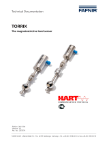
The design of the level sensor system is shown in gure 1 in the form
of embodiment furnished with a screwed-in element. Provided in the
probe head (1) is the area of connection and adjustment protected by
lid (2). The electrical connection is via an M16x1.5 cable gland (3) at
the top of the probe head while the earth connection (4) is at the bottom
of the probe head. Seated on the probe tube (5) for vertically adjustable
assembling purposes, within the container, is a compression tting (6)
(G 1/2, W 27) or a ange (not shown). The oat (7) serves for conti-
nuously gauging the product level or interface layer, and is held on the
probe tube by a guiding or locking ring (8) etc.
1. Safety information / 2. Description of functions ...

GB
WIKA operating instructions level sensor model FFG
7
13445627.01 12/2010 GB/D/F
The level sensor shown in gure 2 serves for the continuous
measurement of uids. To transmit the liquid level value to the sensor, a
oat is sliding on the sensor tube. The operating principle of the sensor
is based on the magnetostriction eect. The oat contains a magnet
while a wire made of magnetostrictive material is installed under tension
inside the sensor tube. The magnetic eld of the oat is twisting the
wire. A second, temporary magnetic eld is generated along the wire by
a current pulse within the wire. The superposition of the two magnetic
elds will release a mechanical wave on the wire.
At the end of the wire within the sensor head, the mechanical wave is
converted by a piezo-ceramic transducer into an electrical signal. The
starting point of the mechanical wave and, hence, the oat position is
then determined by measuring the transit time.
The results of such measurements are feasibility-tested by a microcon-
troller located in the sensor head and are then converted into a current
value by a digital analog transformer. The sensor is provided with a
2-wire connection so that the current consumption indicates the position
of the oat at the same time. The current values are restricted to a range
of between 3.5 ... 23 mA.
2. Description of functions and design
Fig. 1: Level sensor system model FFG

GB
8
WIKA operating instructions level sensor model FFG
13445627.01 12/2010 GB/D/F
2. Description of functions and design
Transport and storage
Transport and storage for level sensors are only allowed in designed
packaging.
Removal of the transportation packing and
transportation safety bolts
Carefully remove the level sensor from the transportation packing.
Please observe the warning on the shipment packing and remove all
transportation safety bolts, prior to discharging the level sensor system.
Never remove the level sensor system from the packing by applying
force to the guide tube!
Prior to assembly the safety bands are to be removed from the oats.
Make sure that all packing elements have been removed and that the
oats are free to move on the guide tube.
Fig. 2: Functional principle

GB
WIKA operating instructions level sensor model FFG
9
13445627.01 12/2010 GB/D/F
3. Area of application
The level sensor system is available for employment in varying container
heights of between 200 and 6000 mm. Flange-model or screw-model
designs are available allowing a stepless positioning within the contai-
ner, depending on the design thereof.
Probe tube and oat can be installed up to the screw element or ange
in areas exposed to danger of explosion, in which electric units of the
category 1/2 (zone 0) are required. In respect of the bypass model, the
complete system is allowed to be installed in areas exposed to danger
of explosion that require electric unit of category 2 (zone 1). The sensor
head of the level sensor can be operated at ambient temperatures
of between -40 ... +85 °C, while the sensor tube is operable within a
temperature range of between -25 ... +250 °C. The permitted process
temperatures in case of employment in zones subject to danger of
explosion that require operating units of categories 1/2 or 2, are set out
in the tables.
The technical specications set out in these operating
instructions should be observed.
4. Assembly
Assembly and servicing in areas exposed to danger of
explosion shall be in accordance with the provisions
stipulated by ElexV and the Act on Appliance Safety
and shall be in accordance with all applicable rules
of technology and the present operating instructions.
Moreover, please also observe all local safety and
accident preventing regulations that have not been
expressly mentioned in these operating instructions.
Make sure, during assembly that the probe tube is not
bent and that the oat is not exposed to shock.
The level sensor having Ex-approval must be so
mounted that the probe head is not located in the
Ex-zone 0.
3. Area of application / 4. Assembly

GB
10
WIKA operating instructions level sensor model FFG
13445627.01 12/2010 GB/D/F
The level sensor systems, depending on the design thereof, will be
mounted into the container by means of a ange or a screw-in thread.
Make sure, prior to assembly, that the assembly port provided on
the container and the attachment means of the level sensor system
conform in size and dimension. Depending on the design of the level
sensor system, assembly thereof into the container must be externally.
Assembly must be in the vertical position. To insure a safe function,
the angle of assembly is allowed to dier from the vertical by 30° max.
The guide tube of the level sensor is to be externally introduced through
the assembly port of the container. Attachment thereof is by tightening
the screw-in thread in respect of threaded plugs; by bolting the cap nut
in respect of dairy pipe ttings; screwing in respect of ange-model
designs or closing of the locking rings (articulated clamp) in triclamp-
model clamp connections.
■
Level sensors having screw-in threads are to be screwed
across the entire thread length.
■
Level sensor systems having dairy pipe ttings are
furnished, ex factory, with suitable cap nuts.
■
Level sensor systems of ange-model design are to be
xed by suitable screws, washers and nuts.
■
Level sensor systems having clamp connections of the
triclamp model are to be secured by means of suitable
locking rings (articulated clamp).
Please observe the torque value of the screws!
4. Assembly
Suitable sealants should be used. Please make sure that the sealing
material is resistant to the uid and its vapours and to the anticipated
temperatures and pressures.
In designs having oats mounted thereon the diameters of which
exceed the core diameter of the mounting port the oats should be
removed from the guide tube prior to assembly thereof.

GB
WIKA operating instructions level sensor model FFG
11
13445627.01 12/2010 GB/D/F
4. Assembly
Fig. 3: Level sensor system with mounting thread
1 Terminal box
2 Cable gland
3 Mounting thread
4 Gasket
5 Guide tube
6 Float
7 PTFE washer
8 Set collar or tension clamp
Procedure:
■
To mark upper side of oats (e.g. by "top")
■
To mark position of locating rings
■
To remove locating rings and drop protection rings
■
To lift oats
■
To assemble the level sensor
■
To mount oats, locating rings and drop protection rings from inside
of container. Please observe markings!
The drop protection rings serve to avoid the formation of
ignition sparks in the event of an impact of the oat on the
locating ring. No operation is permitted without the use of
drop protection rings.

GB
When using a oat made of titanium in areas exposed to
danger of explosion of category 1/2, please make sure,
during installation and operation, that the said oat will
generate no sparks caused by friction or shock.
Maximum lengths of guide tubes
Depending on the length and design of the guide tube, the
level sensor must be xed to the container bottom
(see table).
12
WIKA operating instructions level sensor model FFG
13445627.01 12/2010 GB/D/F
4. Montage
Guide tube Max. guide tube length L
Version A Version B
12 x 1 mm 660 3500
16 x 1 mm 1270 6000
17.2 x 1.6 mm 2100 6000
18 x 1.5 mm 3000 6000
Version A: Fixed to the tank ceiling Version B: Fixed to the tank ceiling
and oor
L... L...

GB
WIKA operating instructions level sensor model FFG
13
13445627.01 12/2010 GB/D/F
5. Electrical connection
The level sensor in areas exposed to danger of explosion
are allowed to be connected to buer ampliers only if these
are certicated by a generally accepted test institute, and
if the electric specications thereof are compliant with the
following conditions:
Ui = ≤ 30 V
Ii = ≤ 0.2 A
Pi = ≤ 1 W
Level sensor model FFG
(Standard and pharmaceutical design) EEx ia
The electric specications (see product label) and the additional provisi-
ons for installing intrinsically safe circuits should be abided by. No work
is allowed to be carried out unless by trained experts.
The electric connection of the level sensor is via built-in clamps. The
given connecting pattern is conveyed by the connection diagram within
the interior of the terminal box, or by the mounting and operating instruc-
tions.
Selection of connection cable
Wiring requires a 2-core cable to be connected in the
probe head of the sensor. The cable cross-section must be
selected so that the supply voltage on the level sensor is no
less than 10 V in the borderline case of maximum current
consumption (21.5 mA) in a given cable length L.
A copper cable with a cable cross-section of 1 mm² and a
length of 100 m (100 m forward and 100 m return line) has a
resistance of 3.4 Ω (R = 0.034 Ω x L(m)/F(mm²).
5. Electrical connection

GB
14
WIKA operating instructions level sensor model FFG
13445627.01 12/2010 GB/D/F
If a supplier provides, for example, 13 V at 21.5 mA, the sum
of resistors contained in the supply line is not allowed to be
in excess of (13 V – 10 V) / 0.0215 A = 139 Ω. If the cable is
of a cross-section of 0.5 mm² and if no burden is contained
in the line, the feeder line is not allowed to have a length
greater than L = 139 (Ω) x 0.5 (mm²)/0.034 m = 2050 m.
Note the given connecting pattern
The connection should be carried out with light-blue-marked cable. The
diameter of the connecting cable must be within the clamping range
of the cable gland (5-10 mm). Using other cable diameters involves the
danger of moisture ingress.
The use of individual strands is not permitted!
Cable capacity and inductivity
When determining the required cable length, the highest
permitted inductivities and capacities of the connected
intrinsically safe control unit should be observed. These
values are not allowed to be exceeded.
Connecting the cable
Wiring must be in a voltage-free condition. Compliance
with all special VDE regulations and local provisions of
installation is imperative.
■
Unscrew lid (1) of probe head with open-end wrench
■
Loosen sleeve nut (2) of cable bolting
■
Insert dual-core cable(4) through sleeve nut and re-tighten the same
■
Connect dual-core cable (4) to screw terminals in probe head,
marked by (+) and (-)
■
Re-screw lid (1) on probe head
5. Electrical connection

GB
WIKA operating instructions level sensor model FFG
15
13445627.01 12/2010 GB/D/F
Observe the general prescriptions of installation!
The connections on the separating amplier are marked
accordingly. During connection of the poles, there will be no
current ow.
Potential balance and PE connection
Grounding or potential balance can be via the earth termi-
nal at the bottom side of the probe head.
Protect the probe head against the ingress of water!
Safe sealing of the cable inlet is safeguarded from a
5 mm outer diameter of the cable.
Tighten cable glands. Lock lid of probe head.
Wiring of the level sensor for supplying purposes (in Ex, preferably
blue cable) is by a dual-core cable. The cable cross-section is to be
selected so that the supply voltage to the sensor is no less than 10 V in
the borderline case of maximum current consumption (21.5 mA) with a
given cable length L.
Fig. 4: Electrical connection of the level sensor
5. Electrical connection

GB
A copper cable having a length of 100 m (100 m forward and 100 m
return line) has a resistance of 3.4 Ω in a cable cross-section of 1 mm².
(R = 0.034 Ω x L(m)/F(mm²). If a supplier generates, for example, 13 V
at 21.5 mA, the resistivity R is allowed to be 3 V/0.0215 A = 139 Ω. If the
cable is of a cross-section of 0.5 mm² , the feeder line is allowed to have
a length L = R(Ω) x F(mm²)/0.034 m = 2044 m.
Connecting pattern in an area exposed to danger of explosion
16
WIKA operating instructions level sensor model FFG
13445627.01 12/2010 GB/D/F
Fig. 5: Connecting diagram of the Ex-design
Model FFG (Ex-design Separating amplier
5. Electrical connection
Minimum voltage: U
min
= 10 V + 0.0215 A x ∑R
∑R = Sum of all cable resistancess including feeder line and burden
Adjusting measures
Measuring range span
Two keys and one illuminated diode (LED) in the connecting area of the
probe head serve for adjusting the 4 mA- and 20 mA-points. The level
sensor system is adjusted, ex factory, to the maximum range from 4 mA
on the probe base to 20 mA at the probe head. The range of measure-
ment for adaptation to the given container can be individually adjusted;
however, the distance must be no less than 5 mm. Otherwise the indica-
tion direction of the sensor is automatically reversed.
For further details of adjusting the range of measurement reference
(see Fig. 6):
■
Unscrew lid (1) of probe head with open-end wrench
■
Keep 4 mA-key (2) pressed for no less than 3 seconds
Power supply

GB
WIKA operating instructions level sensor model FFG
17
13445627.01 12/2010 GB/D/F
5. Electrical connection
The level sensor system now is in the adjusting mode with the green
LED (4) "Cal/Err" ashing. The current consumption of the level sensor
is 12 mA. Without pressing the key again, the level sensor remains in the
adjusting mode for 20 seconds before changing back to the measuring
mode without modifying the adjustment.
To x the 4 mA point within this period
■
move the oat to the desired position,
■
and press down key "4 mA" (2) for a short period of time
(0.1 ... 2 seconds)
The LED display will disappear for 5 seconds, with the current consump-
tion being 4 mA, and thereafter again 12 mA. The level sensor will
remain in the adjusting mode for another 15 seconds before changing
back to the gauging mode.
Fig. 6: Adjustment
To x the 20 mA point within this period
■
advance the oat to the desired position,
■
and press down key "20 mA" (3) for a short period of time
(0.1 ... 2 seconds)

GB
18
WIKA operating instructions level sensor model FFG
13445627.01 12/2010 GB/D/F
The LED display will disappear for 5 seconds, with the current consump-
tion of the level sensor being 20 mA, and thereafter again 12 mA. The
level sensor will remain in the adjusting mode for another 15 seconds
before changing back to the gauging mode.
The new adjustment will not be adopted until it automati-
cally changes from the adjusting mode into the measuring
mode (with LED disappearing). For this reason, the level
sensor should not be cut o from the current supply before.
Current Consumption in the error mode
If the level sensor is due to a failure unable to determine a proper oat
position, i.e. a correct lling level, it will change to an error mode after a
short period of time. The current consumption in the error mode has been
adjusted, ex factory, to 21.5 mA although it can be switched to 3.6 mA,
also.
For adjusting the current consumption in the error mode
(see Fig. 5), proceed as follows
■
unscrew lid (1) of probe head with open-end wrench hold both "4 mA"
(2) and "20 mA" keys (3) simultaneously in pressed for a period of
time of no less than 3 seconds. The green LED (4) "Cal/Err" is ashing
fast, with the current consumption being 16 mA. LED, after 5 seconds,
will cease to ash, displaying, for 2.5 seconds, the set error current
consumption. Once the LED is permanently illuminated, I error =
21.5 mA; once it extinguishes I error = 3.6 mA. With the key not being
pressed down again, the level sensor will remain in the error mode
for another 2.5 seconds before changing back into the gauging mode
without modifying the adjustment. For setting a current consumption of
3.6 mA during the 10-second dwelling time in the error mode
■
briey press down the key "4 mA" key (2) (for 0.1 ... 2 seconds). For
adjusting a current consumption of 21.5 mA during the 10-second
dwelling time in the error mode
■
briey press down the "20 mA" key (3) (for 0.1 ... 2 seconds).
The new adjustment will not be adopted by the level sensor
until it automatically changes from the adjusting mode to the
gauging mode (with LED disappearing). The level sensor
should, therefore, not be cut o from the power supply before.
5. Electrical connection

GB
WIKA operating instructions level sensor model FFG
19
13445627.01 12/2010 GB/D/F
6. Maintenance
The level transmitters operate free of maintenance and wear when used
properly.
However, within the scope of routine inspections they should undergo
visual checks and be part of the container pressure test.
7. Trouble shooting
In the following table the most frequent failure causes and the required
corrective measures are listed.
Trouble Cause Measure of correction
No or
undened
function
Incorrect terminal positioning
Compare with connecting
diagram
Insulation secured under
terminals
Check terminal points
Locating rings displaced or
incorrectly mounted after
removal from the guide tube
Check position of locating
ring
Incorrect
0 ... 100 %
values
Float wrongly mounted Turn oat around
Incorrect specications in
order
Contact factory
Waveguide in defective con-
dition caused by mechanical
interference
Return to factory
Incorrect setting Re-adjust or contact factory
Cannot be
attached to the
proper point
within
the container
Thread size or ange size
of WFFG-T...EX sensor and
container not conforming
Re-design the container
Re-design of level sensor
in factory
Thread of attachment sleeve
on container in defective
condition
Re-work thread or replace
mounting socket
Screw-in thread on level sen-
sor in defective condition
Return to factory
Please give us a call in case of any diculties. We will do everything we
can to provide you with the required advice and help.
6. Maintenance / 7. Trouble shooting

GB
20
WIKA operating instructions level sensor model FFG
13445627.01 12/2010 GB/D/F
8. Technical specications
Type of protection, explosion and temperature class
II 1/2 G EEx ia IIC T6–T2 II 2 D T95 °C IP 6X
II 1/2 G EEx ia IIB T6–T2 II 2 D T95 °C IP 6X
(pharmaceutical design)
Equipment group: II
Equipment category: 1G (oat and guide tube)
2G / 2D (connecting case)
Type of protection: EEx ia
Explosive sub-group: IIC or IIB (drop protection PTFE)
Temperature class: T2, T3, T4, T5, T6
Summary of electrical specications of authorized design
variants
Power supply:
Voltage Consumption
of power
Inductivity
(extern.
eective)
Capacity
(extern.
eective)
Type of
protection
DC 10 ... 30 V max. 700 mW max. 250 μH max. 5 nF EEx ia
Permissible data of control unit:
Ui Ii Pi Li Ci Type of protection
≤ 30 V ≤ 200 mA ≤ 1 ≥ 250 μH ≥ 5 nF EEx ia
8. Technical specications
/