Page is loading ...

052588-001r5 Printed in USA June, 2017
I
NSTALLATION
M
ANUAL
MIRAGE 2-STAGE
with Direct Response Electronics
RV
Read this manual before installing or servicing this product. Failure to follow the
instructions and safety precautions in this manual can result in personal injury and/or
cause the product to not operate properly.
T
ABLE OF
C
ONTENTS
Product Overview .......................................................................................................................... 1
Specifications ................................................................................................................................. 1
Component Checklist.............................................................................................................................. 2
Installation – Mechanical .............................................................................................................. 4
Required Pre-Installation Parameters ..................................................................................................... 4
Mounting Plate Layout and Installation ................................................................................................... 5
Mounting Height ............................................................................................................................. 5
Alternate Mounting Plate Attachment Method ................................................................................ 7
Mounting the Awning Unit ....................................................................................................................... 7
Securing the Awning ............................................................................................................................... 7
Electrical Installation .................................................................................................................... 8
Key Pad Installation ................................................................................................................................ 8
Control Box Installation ........................................................................................................................... 9
Installing the Remote Receiver ............................................................................................................. 10
Ignition Lockout Sensor Installation (Optional) ..................................................................................... 11
Wiring Diagram – Single Awning .......................................................................................................... 12
Wiring Diagram – 2-Awnings ................................................................................................................ 13
Wiring Diagram – 4 Awnings ................................................................................................................ 15
Connection Flex w/ "110VDR" Control Boxes ...................................................................................... 17
Optional Manual Bypass Switch ........................................................................................................... 17
Optional LED Lighting Switch Installation ............................................................................................. 18
Testing the System ............................................................................................................................... 19
Standard System Adjustments .................................................................................................. 20
Adjusting the Pitch ................................................................................................................................ 21
Manual Override ................................................................................................................................... 21
Setting the Motor Limits ........................................................................................................................ 22

P
ROPRIETARY
S
TATEMENT
The Mirage 2-Stage Patio Awning is a product of Carefree of Colorado, located in Broomfield, Colorado,
USA. The information contained in or disclosed in this document is considered proprietary to Carefree of
Colorado. Every effort has been made to ensure that the information presented in the document is
accurate and complete. However, Carefree of Colorado assumes no liability for errors or for any damages
that result from the use of this document.
The information contained in this manual pertains to the current configuration of the models listed on the
title page. Earlier model configurations may differ from the information given. Carefree of Colorado
reserves the right to cancel, change, alter or add any parts and assemblies, described in this manual,
without prior notice.
Carefree of Colorado agrees to allow the reproduction of this document for use with Carefree of Colorado
products only. Any other reproduction or translation of this document in whole or part is strictly prohibited
without prior written approval from Carefree of Colorado.
S
AFETY
I
NFORMATION
This is the safety alert symbol. It is used to alert individuals to potential
personal injury hazards. Obey all safety messages that follow this symbol to
avoid possible personal injury or death.
WARNING
Indicates a hazardous situation, which if not avoided, could result in death or
serious bodily injury.
CAUTION
Indicates a hazardous situation, which if not avoided, may result in minor or
moderate bodily injury.
NOTICE
Indicates a situation that may result in equipment-related damage.
General Safety:
WARNING
Shock Hazard. Always disconnect battery or power source before
working on or around the electrical system.
WARNING
Always wear appropriate safety equipment (i.e. goggles).
CAUTION
Always use appropriate lifting devices and/or helpers when lifting or
holding heavy objects.
NOTICE
When using fasteners, do not over tighten. Soft materials such as fiberglass and
aluminum can be "stripped out" and lose the ability to grip and hold.
CALIFORNIA PROPOSITION 65
WARNING
This product contains chemicals known to the state of California to cause
cancer or birth defects or other reproductive harm. California’s Proposition 65 requires this
warning to be given to customers in the state of California.
Reference Publications located @ www.carefreeofcolorado.com:'
052588-001: Mirage 2-Stage Installation Manual
052588-201: Mirage 2-Stage Owner's Manual
Carefree of Colorado 2145 W. 6
th
Avenue Broomfield, CO 80020 a Scott Fetzer company
Electric components in this product have been tested by the following agencies:
Motor: UL Recogonized (USA)
CSA Approved (Canada)
Controls: UL Listed (USA & Canada)

Carefree of Colorado Installation Manual MIRAGE 2-STAGE
052588-001r5 1
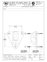
PRODUCT OVERVIEW
The Mirage 2-Stage Patio Awning offers the coach owner an awning system that provides as much or as
little shade as required. The canopy is housed in an aluminum case that easily blends in with the coach
roof.
Each unit is equipped with lateral support arms that are the strongest available on the market. No vertical
arms interfere with coach sidewalls or equipment that may be mounted on the roof.
Carefree’s 110V Direct Response system provides interior pushbutton controls for standard extend/retract
functions. At the master control panel the auto-retract system can be engaged to automatically retract the awning
in windy conditions. Sensitivity can be set to respond to a variety of wind speed conditions. An RF remote is
available with the Direct Response system.
Specifications
L
ENGTHS:
12' – 21'
EXTENSIONS:
10’ (standard)
COLORS AVAILABLE:
Case: Black
Fabric: Woven Acrylic Fabric refer to order form for available colors
MOTOR SPECIFICATIONS:
Available in LH or RH configurations
Type:
Tubular Motor
Power:
120V, 60HZ, 2.5A
Torque:
60 nm
Speed:
14 RPM
Cycle:
40 Sec ON / 1 Min OFF
6.35"
8.25"
6.38"
Awning Length
M2004
Mounting Plates (x4)

MIRAGE 2-STAGE Installation Manual Carefree of Colorado
2 052588-001r5
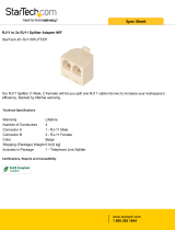
COMPONENT CHECKLIST
M2003
Single Awning Electronics
Dual Awning Electronics
4-Awning Electronics
5
1
2
9
7
8
10 11
12
13
14
15
16
17
18
19
20
6
Power
On/Off
Stop
Motion Sensor
Low High
Awning Control
Extend Retract
All Awnings
Awning 2
Awning 1
Extend Retract
Power
On/Off
Awning 4
Motion Sensor
Low High
Stop
Awning 1
Awning 2
Awning 3
Extend Retract
All Awnings
Driver Side
Passenger Side
Power On/Off
Motion Sensor
Low High
Awning Control
Extend
Retract
Stop
21
3
4
ON
OFF
22

Carefree of Colorado Installation Manual MIRAGE 2-STAGE
052588-001r5 3
I
TEM DESCRIPTION QTY NOTE
1
Mirage 2-Stage Awning Assembly 1 1
2
Mounting Bracket 4
3
Hardware Kit (Roof Mount) 8
Screw, Thread Forming 1/4"-20 x 3/4" 4
Screw 3/8"-16 x 1 1/4" 24
Flat Washer 3/8" 24
Nut, Nylock 3/8" 24
Hex Key 7mm x 133mm 1
4
Hardware Kit (Wall Mount) 8
Screw, Thread Forming 1/4"-20 x 3/4" 4
Screw, Rolock 3/8" x1 1/2" 24
Hex Key 7mm x 133mm 1
5
Hardware Kit (Through Wall) 8
Backing Plate 6
Backing Plate Cover 6
6
Control Box Single Awning 1 2
7
Key Pad Assy Single Awning 1 2,3
8
Remote Control Key FOB, 433MHz Single Awning 1 2,4
9
Control Box Dual Awning 1 2
10
Key Pad Dual Awning 1 2,3
11
Remote w/ stop, 433 MHz Dual Awning 1 2,4
12
Control Box 1 (Motor #1, Motor #2) 4-Awning Combo 1 2
13
Control Box 2 (Motor #3, Motor #4) 4-Awning Combo 1 2
14
Key Pad 4-Awning Combo 1 2,3
15
Remote w/ stop, 433 MHz 4-Awning Combo 1 2,4
16
RF Receiver, 433 MHz 1
17
RJ11 Cable 60" 1 5
18
RJ11 Cable 240" 1 7
19
Sensor, Ignition Lock-Out 1 5,6
20
Splitter 1 5,6
21
Coupler, Cable 1 7
22
Switch and Fuse Kit, LED Lighting 1 9
Notes: 1. Awning configuration is specified at time of order, including awning length, LH or RH
configuration, fabric color etc. Check awning assembly against original purchase order.
2. Electronic components are not interchangeable between systems.
3. Mounting screws are included with switches and mounting plates.
4. Additional remotes can be ordered separately.
5. 60" cable (item 17) is furnished with items 7, 10 and 14, one additional cable is furnished
with the 4-awning control boxes (items 12, 13).
6. The optional ignition lockout and splitter (items 19, 20) must be ordered separately. Two
versions of the lockout sensor are available, refer to page 11 for description.
7. Long cable (item 18) and /or coupler (item 21) are specified at time of order.
8. Hardware kits (items 3, 4 & 5) are specified at time of order.
9. The LED switch and fuse kit (item 22) is optional and ordered separately for the factory
installed LED lighting option. LED lighting is optional and specified at time of order.

MIRAGE
2-STAGE Installation Manual Carefree of Colorado
4 052588-001r5
INSTALLATION – MECHANICAL
WARNING
The Mirage awning has significant weight. The awning and attaching brackets must
be securely attached to the structural frame of the vehicle. Consult the coach manufacturer to determine
the type and position of the structural members and the structure's ability to support the weight. Failure
to heed this warning can result in serious injury and property damage.
CAUTION
The awning is extremely heavy. Moving and/or lifting the awning
requires a minimum of 3 people. The use of a lifting device is strongly recommended.
R
EQUIRED
P
RE
-I
NSTALLATION
P
ARAMETERS
Prior to installing the awning system, the installer must determine the layout of the system and provide
specific construction elements to successfully assemble the awning components.
Prior to installing the awning, the installer must determine the layout of the specific construction elements to
successfully assemble and mount the awning.
1. Determine the location, size and type of structural framing in the area where the awning is to be mounted.
1.1. There must be structural framing at the awning mount locations. Fiberglass or sheet metal siding alone is
NOT
strong enough to support the weight of the awning!
1.2. If the framing is not obvious, it may be possible to use a stud finder or other similar device to locate the
frame.
1.3. If in doubt, contact the coach manufacturer to determine the type and position of the structural frame.
2. Determine the mounting locations for the control box and switch assemblies.
2.1. For 110VAC installations, the installer must provide enclosed junction boxes for all wire splices. Boxes
are required in conformance with prevailing construction codes.
2.2. At the control box location, AC input is required. It is recommended that the installer provide a
dedicated AC circuit for the awning system that is protected by an appropriate sized fuse/circuit
breaker. Each patio awning draws a maximum of 3 amps.
2.3. The motion sensor for the Direct Response system is mounted on the lead rail of the patio awning. 10
feet cable is available from the awning mount position, and will require a routing path to the control box. If
the control box is located at a distance greater than 10 feet, the installer must provide a terminated jumper
cable from the box location to the cable end.

Carefree of Colorado Installation Manual MIRAGE 2-STAGE
052588-001r5 5
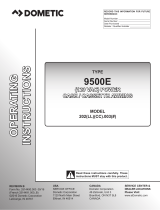
MOUNTING PLATE LAYOUT AND INSTALLATION
Mounting Height
The chart below provides the minimum distance from the top of a projection (i.e. open door or slide out) to
the bottom of the mounting plate. This provides clearance for the travel path of the lead rail.
Below is the mounting pattern using four (4) mounting brackets
Wall
0, 0
A Projection (Door/Slideout)
0" 12" 24" 36" 48" 60" 72"
B Min. Mounting Height (min. pitch)
3" 5.5" 8.25" 12" 16" 21" 26"
B Min. Mounting Height (max. pitch)
3" 8" 14" 20.5" 28" 36.5" 45"
The minimum mounting height (B) is measured from the uppermost edge of the projection (i.e. door, slideout
room flange) to the bottom of the mounting plate. The value given is a minimum requirement, adjust upward as
required to clear casing, trim etc.
Maximum Height of Projection
A
B
Bottom of Case
64"
42"
110"
Mounting Clearance -
2” below travel path
98"
Travel Path
Trailing Edge of Lead Rail
32º
12º (minimum pitch)
24º (maximum pitch)
44º
Travel Path (minimum pitch)
Trailing Edge of Lead Rail
Travel Path (maximum pitch)
Trailing Edge of Lead Rail
5.75,-2.25
5.75,-3.25
4.75,-2
4.75,-2.75
.75, -.25
1.25, -1
2.25, -1.5
2.75, -1.6
2.75, -2
3.75, -2.5
3.75,-2.75
0, 0
1.75, -1.25
-3.5
-6
-6.25
-12
-10
-18.5
-14
-26
-19
-34.5
-24
-43
12 24 36 48 60 72
-3.5
-6
12

MIRAGE 2-STAGE Installation Manual Carefree of Colorado
6 052588-001r5
A (feet) B (inches) C (inches) A (feet) B (inches) C (inches) A (feet) B (inches) C (inches)
12’ 13 51.25 16’ 13 67.75 20’ 15.5 85.75
13’ 13 54.25 17’ 13 70.75 21’ 15.5 88.75
14’ 13 57.25 18’ 13 73.75
15’ 13 64.75 19’ 13 76.75
NOTICE If the mounting plates must be located differently than the recommended positions, It
is important that for proper support and awning operation, the mounting brackets must be
positioned behind the spring arm case connectors.
1. Determine the location of the awning mounts:
1.1 Mounting area must be flat and clear of obstacles,
1.2 The awnings have appreciable weight; the mounting screws
MUST fasten into the structure.
1.3 Drill six (6) 7/16" holes in each mounting plate to match the structural locations.
2. Position the mounting plates on the vehicle. Horizontally position the plates using the dimensions in
the chart above.
NOTE: Three mounting hardware kits are available.
For wall mount applications, use the kit with rolock screws (item 4 on page 2) to attach the
mounting plates to the vehicle's structural framework.
For roof mount applications using installer furnished supports, use the screws and nuts (item 3 on
page 2) to attach mounting plates to supports.
For through the wall mounting use the backing plate and cover (item 5 on page 2). Please note
that installer must furnish the 3/8" screws, washers and nuts to fit the installation.
3. For rolock thread cutting screws:
3.1 For each plate, on one end of the plate, use the plate as a template and drill an 11/32” pilot hole
into the structure. Attach the plate using a 3/8"-16 x 1 1/2" thread cutting screw.
3.2 Confirm position of plate and repeat step 6 on the opposite end of the mounting plate.
3.3 Continue to drill and attach using the 3/8"-16 x 1 1/2" thread cutting screws. Use six (6) screws
minimum per plate.
4. For installer furnished roof mount supports :
4.1 Align each plate with the supports, use the plate as a template and drill a 7/16” pilot hole into the
structure. Attach the plate using a 3/8" x 1 1/4" screw, washer and nylock nut.
4.2 Confirm position of plate and repeat step 6 on the opposite end of the mounting plate.
4.3 Continue to drill and attach using the 3/8" screws, washers and nuts. Use six (6) screws per plate.
5. At the motor location, drill one (1) 1/2” hole through outer surface. The position should be behind the motor
end cap position.
6.38"
A (Awning Length)
B B
CC
Mounting Bracket (x4)
M2005
Screw Grooves
Drill Ø 7/16" (x6)
Hole Pattern to Match Structural Frame
21.5"

Carefree of Colorado Installation Manual MIRAGE 2-STAGE
052588-001r5 7
Alternate Mounting Plate Attachment Method
NOTICE This method should be used only as required. Primary attachment MUST be into the
structure as described above.
When it is not possible to attach into structure or if
the screws will be exposed inside the coach, an
alternate method is to use a backing plate and
cover. The installer must furnish the 3/8 bolts,
washers and lock nuts.
1. Using the mounting plate as a template, drill
7/16” holes through the wall. The inside of
the wall must be accessible.
2. Attach as shown using a backing plate and
cover. Torque nuts to 50 in-lb.
MOUNTING THE AWNING UNIT
1. While lifting the awning, route the awning motor wires
through the 1/2” hole drilled previously.
NOTE: It is necessary to first insert the sensor cable and
connector through the hole then insert the motor wires.
2. Set the awning into the hooks of the mounting plate.
3. Adjust the horizontal position of the awning as
required.
SECURING THE AWNING
NOTE: This procedure requires opening the awning. Follow the Manual Override instructions on page 21.
These steps can be done after the electrical installation when motorized power is available.
1. Adjust the awning horizontally as required.
2. Open the awning approximately 3 feet to access the back panel of the awning case.
3. Drill four (4) 3/16” holes through the case, mounting plates and into wall (do not go through interior
surfaces of wall) in the gray areas shown above. The recommended areas match the positions of the
mounting plates.
4. Ream out the holes in the case only to 5/16”.
5. Attach the awning case to the mounting plate and wall using four (4) 1/4" x 3/4" thread forming screws.
6. From inside, seal the wires and access hole with a quality silicone sealant.
Drill in this area
Location matches position
of Mounting Plate
M2007
Ø 3/16” Thru Case and Bracket
Ream case only to Ø 5/16”
1/4 x 3/4 Thread Forming Screw (4 plcs)
Mounting Plate
3/8 Bolt
Cover
Backing Plate
Washer
3/8 Lock Nut
7/16 Holes
thru Wall
MIRAGE014
M2006
Back Plate
Mounting Plate

MIRAGE
2-STAGE Installation Manual Carefree of Colorado
8 052588-001r5
ELECTRICAL INSTALLATION
WARNING
Shock Hazard. Always disconnect battery or power source before
working on or around the electrical system.
IMPORTANT NOTICES:
Failure to follow the wiring instructions in this publication may void the warranty.
All wiring must conform to NEC (National Electrical Code) and local codes.
D
O NOT wire two or more motors to one motor controller.
The SO cable from the 110VAC awning motor can only pass directly through a wall, it can not be laid
up in the wall and must be connected to NM wire or individual wires in conduit no more than 6 inches
past the point of entry.
The installer must provide enclosed junction boxes for all 110VAC wire splices. Boxes are required in
conformance with prevailing construction codes. Installers are required to furnish the UL approved
electrical boxes where required.
At the control box location, AC input is required. It is recommended that the installer provide a
dedicated AC circuit for the awning system that is protected by an appropriate sized fuse/circuit
breaker. Each patio awning draws a maximum of 3 amps.
The motion sensor for the Direct Response system is mounted on the patio
awning. 10 feet cable is available from the awning wall mount, and will require a
routing path to the control box. If the control box is located at a distance greater
than 10 feet, the installer must provide a terminated jumper cable from the box
location to the cable end.
Terminated cable is a 4-wire RJ11 terminated phone cord (straight, no twist).
NOTE: Cable lengths of the furnished cables are listed in the chart with the
system wiring diagram. If a connection requires a length greater than the supplied
cable, the installer must provide a terminated jumper cable from the box location
to the cable end. Terminated cables are 4-wire RJ11 terminated phone cord
(straight, no twist).
K
EY
P
AD
I
NSTALLATION
1. Locate the mounting location of the key pad. The key pad
requires a flat area approximately 2 3/4" wide by 4 1/2" tall.
2. Use the mounting plate as a template and mark the location of
the two mounting holes.
3. Remove the plate, mark and cut a 1" hole in the position
shown.
4. Mount the plate to the surface using the included screws.
5. Route the 25 foot RJ11 cable from the control box location
through the wall and mounting plate.
6. Attach the cable to the back of the key pad then attach the key
pad to the mounting plate.
NOTE: The key pad attaches to the plate with magnetic
latches. No additional attaching hardware is required.
Black
Red
Green
Black
Yellow
Red
Green
Yellow
Cables are 4-wire RJ11
terminated phone cord
(straight, no twist).
RTA031
1.25”
O 1” min.
O .125” Pilot Hole
(2 plcs)
Keypad
Cable
Mounting Plate
Key Pad
Paramount005
4.5”
3.25”
(ref)
2.75”
#6 x 1/2
Screw (2)

Carefree of Colorado Installation Manual MIRAGE 2-STAGE
052588-001r5 9
CONTROL BOX INSTALLATION
NOTES:
a) For Multiple Awing Installations: The awning motor that is connected to the controller board marked "motor
#1" will correspond with "Awning 1" on the touch pad control and remote. The awning motor connected to
"motor #2" will correspond with "Awning 2" on the controls etc.
b) For 4-Awning Installations: Awnings connected to motor #1 & #2 correspond to "Passenger Side Awnings",
awnings connected to motor #3 & #4 correspond to "Driver Side Awnings".
c) The control boxes are not suitable for exterior installations and must be mounted in the
INTERIOR of the
vehicle.
For Single Awning installations: refer to wiring diagram on page 12.
For 2-Awning installations: refer to wiring diagram on page 13.
For 4-Awning installations: refer to wiring diagram on page 15.
1. Locate the mounting location of the control box(es). Each box requires a flat area approximately 6 1/2"
x 6 1/2" with a clearance depth of 2 3/8".
For 4 awning installations: A 60" jumper cable is used between the two control boxes. This allows
approximately 55" of cable between the boxes. Position the boxes to allow the jumper to be connected and
routed with some slack in the cable.
2. Remove the lid. Attach the box to the mounting
surface using a minimum of two (2) #8 x 3/4 screws
each. The screws must be mounted in opposite
corners.
3. Route a 2-conductor 14AWG NM wire w/ ground from
the AC power source to the box. It is recommended
that the installer provide a dedicated AC circuit that is
protected by an appropriate sized fuse/circuit
breaker. Each patio awning draws a maximum of 3
amps.
NOTE: Each board must have a 110VAC supply. The diagram shows a separate power source for each
box; each power source is spliced with wire nuts to power both boards in a box.
4. Connect the wires to the control box circuit boards as shown in the wiring diagram (Detail A).
5. Route the motor wires from awning #1 to controller #1 (motor#1); attach the wires to the terminals as shown.
NOTE: For RH motor configurations:
RED WIRE goes to terminal (1); BLACK WIRE goes to terminal (2).
For LH motor configurations:
RED WIRE goes to terminal (2): BLACK WIRE goes to terminal (1).
6. Attach the RJ11 cable from the sensor of awning #1 to the "AMD" receptacle of controller #1.
7. Repeat step 5 and 6 for the other awnings.
8. After testing connections, use Loctite 29005 or equivalent to secure screws in terminal block.
9. Attach the remaining RJ11 cables as shown in the wiring diagram. Use the slot cutouts in the box to
route the phone cables.
NOTE: The key pad and RF receiver only attach to controller #1.
#8 x 3/4 Screw (2)
RTA019c
6 1/2”
(typ)
2 3/8”

MIRAGE 2-STAGE Installation Manual Carefree of Colorado
10 052588-001r5
INSTALLING THE REMOTE RECEIVER
1. Determine the location of the RF receiver:
1.1 Do not mount the unit near heat producing elements such as LP appliances or engine exhaust
components.
1.2 For best reception, do not mount the unit near or on a metal surface.
1.3 Mount the unit with the antenna pointing up.
1.4 The included cable is approximately 60 inches long.
Mount the unit close enough to the splitter or control
box so that the cord can be connected without
stressing the connections.
1.5 Allow adequate room below the box to access the
connector jack, programming button and indicator
light.
2. Position the control box and secure using two (2) #6 x 1/2” screws.
NOTE: If the box is mounted on a surface that is less that 1/2” thick, the screws will protrude through
the opposite side of the surface.
3. Connect the cable to the receiver.
4. Route the cable to the splitter; or, to the control box and connect to “EYE”.
P
ROGRAMMING THE REMOTE RECEIVER
1. Power to the control box must be on.
2. Press and release the “Press to Learn Transmitter” button on the bottom of the
receiver box. The receiver is in program mode when the red light comes on.
3. Press and release the stop button on the remote. The red light will go out
after the receiver learns the remote signal.
NOTE: For single awning key FOB remotes: Pressing the stop button will
cause the blue up arrow button to default as the open (extend) function. If a
function button is pressed to train the receiver, it will be programmed as the
open (extend) button. Example: Pressing the bottom button will program
the bottom button for extend and the top button as retract.
4. Repeat for each additional remote.
O
PERATIONAL NOTES:
Transmitter and receiver operate on a frequency of 433 MHz.
The receiver exits the program mode after ten seconds.
If the light does not come on above, the memory is full and must be cleared. If the light still does not come on,
check the continuity of the cord between the boxes and repair or replace as required. Pin 1 of the 1
st
connector
goes to pin 1 of the 2
nd
connector etc.
If the light does not go out in above, the receiver already knows the transmitter's signal or the battery in the
remote needs to be replaced.
To clear the memory:
PRESS AND HOLD the transmitter learn button. While holding the button, the indicator light
should be OFF for the full 5 seconds then come on.
The system may be programmed for up to 5 remotes. Additional remotes may be ordered separately.
RTA034
1”
TO
EYE PORT
on RP24
Program
Mode
Press to Learn
Transmitter
UP
3 7/8”
4 3/16”
#6 x 1/2
Screw (2)
DR020
TO
EYE PORT
on RP24
Program
Mode
Press to Learn
Transmitter
UP
Program
Button
Indicator
Light
RR

Carefree of Colorado Installation Manual MIRAGE 2-STAGE
052588-001r5 11
IGNITION LOCKOUT SENSOR INSTALLATION (OPTIONAL)
Two ignition lockout sensors are available with the Direct Response System.
The STD ignition lockout module disables the extend function when the module receives a current
through a switched 12VDC circuit.
The RTL ignition lockout module will fully retract the awning and disable the extend function when the
module receives a current through a switched 12VDC circuit.
A switched 12VDC source is a line that is "hot" when the ignition switch is in the on position; or, a 12VDC
circuit through a relay that is "hot" when a specific condition is met (i.e. releasing the parking brake).
Relays are not furnished.
1. Disconnect power to the awning. Shut off the power source or pull the appropriate circuit breaker.
2. Locate the control box for the Direct Response System.
3. Open the cover of the control box.
4. For Single Awning Applications:
4.1. Disconnect the remote receiver cable from the "EYE" port in the control box. Do not disconnect the
cable from the receiver box.
4.2. Connect the supplied 6" cable to “EYE” port in the control box.
4.3. Attach the splitter to the other end of the cable.
4.4. Plug the cable from the remote receiver into the splitter.
4.5. Attach the Lock-Out Sensor to the end of the 60" cable. Route the cable as desired and connect
the cable to the splitter.
4.6. Proceed to step 6.
5. For Multiple Awning Applications:
5.1. The module may be connected to the control box as described for single awning applications.
OR
5.2. The module may be directly connected to any open "EYE" port on any of the control boards. It is
not necessary to use the short cable or splitter.
5.3. Proceed to step 6.
NOTE: Wires to the module are not pin specific.
6. Attach one 18-gauge wire to a terminal of the sensor and route the wire to a suitable 12VDC ground.
7. Attach a second 18-gauge wire to the second terminal of the sensor and route the wire to a SWITCHED
12VDC source.
8. Bundle and secure the sensor, cable and wires as required.
9. Reattach the control box cover.

MIRAGE 2-STAGE Installation Manual Carefree of Colorado
12 052588-001r5
WIRING DIAGRAM – SINGLE AWNING
FROM TO (RH CONFIGURATION) TO (LH CONFIGURATION)
Motor Black Control Box
1
Control Box
2
Red
2 1
White 3 3
Ground 6 6
AC Power
Source
White Control Box 4 Control Box 4
Black 5 5
Ground 7 7
Awning Sensor 10’ Cable Control Box “AMD” Control Box “AMD”
Key Pad 60“ Cable Control Box “DSK” Control Box “DSK”
Splitter 60" Cable Control Box "EYE" Control Box "EYE"
RF Receiver 60” Cable Splitter Splitter
Ignition Lockout 60“ Cable Splitter Splitter
Notes: 1. Cable lengths are the lengths of the furnished cables. If a connection requires a length greater than the supplied cable, the
installer must provide a terminated jumper cable from the box location to the cable end.
T O
EYE PO R T
on RP24
Program
Mode
Press to Learn
T ransmitte r
UP
RF
Receiver
GRN
BLK
WHT
RED
DR012a
Ignition
S
witched
+12VDC
12VDC
Ground
Ignition
Lockout
Sensor
(Optional)
Splitter
Sensor
Key Pad
Awning #1
3
5
4
2 Conductor 14AWG
NM Wire w/ Gnd
To 110VAC
AMD SUN AUX EYE DSK
BLK
WHT
RED
GRN
grn
wht
blk
1
7
6
5
4
3
2
1
7
6
5
4
3
2
3 Conductor 14AWG
NM Wire w/ Gnd
Sensor
Remote
Red
Black
White
Green (Ground)
1
Wire Legend:
2
For RH Motor Configurations: Motor Red goes to Pin (1); Motor Black goes to Pin (2)
For LH Motor Configurations: Motor Red goes to Pin (2) Black; Motor Black goes to pin (1)
3
The SO cable from the 110VAC awning motor can only pass through a wall, it cannot be laid up in the wall
and must be connected to NM wire or individual wires in conduit no more than 6 inches past the point of entry.
NOTES:
4
Wires for the Ignition Lock-Out Sensor are not pin specific.
5
Splitter is used only when Optional Lock-Out Sensor is installed. Connect RF Receiver directly to “EYE”
if Lock-Out is not installed.
Detail A
For LH Configuration
Reverse Red & Black Wires
RED
WHT
BLK
GRN
grn
wht
blk
RH Motor Wire Shown
See Detail A for LH Motor
6

Carefree of Colorado Installation Manual MIRAGE 2-STAGE
052588-001r5 13
WIRING DIAGRAM – 2-AWNINGS
TO
EYE PORT
on RP24
Program
Mode
Press to Learn
Transmitter
UP
RF
Receiver
GRN
BLK
WHT
RED
Key Pad
DR014a
Ignition Switched
+12VDC
12VDC
Ground
Ignition
Lockout
Sensor
(Optional)
Sensor #1
Key Pad
Sensor #2
Awning #1
3
5
RED
WHT
BLK
GRN
BLK
WHT
RED
GRN
Wht
Blk
Grn
Wht
Blk
Grn
2 Conductor 14AWG
NM Wire w/ Gnd
To 110VAC
AMDSUNAUXEYEDSK
AMDSUNAUXEYEDSK
1
7
6
5
4
3
2
1
7
6
5
4
3
2
1
7
6
5
4
3
2
3 Conductor 14AWG
NM Wire w/ Gnd
Sensor
GRN
BLK
WHT
RED
Awning #2
Sensor
Remote
3
3 Conductor 14AWG
NM Wire w/ Gnd
DETAIL A
110VAC Power Line In
1
7
6
5
4
3
2
4
4

MIRAGE 2-STAGE Installation Manual Carefree of Colorado
14 052588-001r5
NOTES:
Wire Legend
Awning #1shown as RH Motor, Awning #2shown as LH Motor
For RH Motor Configurations:
Motor Red goes to Pin (1); Motor Black goes to Pin (2)
For LH Motor Configurations:
Motor Red goes to Pin (2); Motor Black goes to Pin (1)
The SO cable from the 110VAC awning motor can only pass directly through a wall; it cannot be laid up in the wall
and must be connected to NM wire or individual wires in conduit no more than 6" past the point of entry.
The RF Receiver and the optional Ignition Lockout may be plugged into any open "EYE" port.
Wires for Ignition Lock-Out Sensor are not pin specific.
For screw type terminals: After testing connections, use Loctite 29005 or equivalent
to secure screws in terminal block
Cables are 4-wire RJ11 terminated phone cord (straight, no twist).
Terminal block designations are for reference only. Actual boards may not be marked.
T
O CONTROL BOARD
FROM MOTOR #1 MOTOR #2
AC Power Source White 4 4
Black 5 5
Ground 7 7
Awning #1 Motor Black
Refer to Flag Note 2
Red
White 3
Ground 6
Awning #2 Motor Black
Refer to Flag Note 2
Red
White 3
Ground 6
#1 Sensor 10’ Cable “AMD”
#2 Sensor 10’ Cable “AMD”
Key Pad 25' Cable "DSK"
RF Receiver 60” Cable "EYE" see note 4
Ignition Lockout 60“ Cable "EYE" see note 4
1
Green (Ground)
White
Red
Black
2
3
4
5
Loctite
29005
Screw Type
Terminal Block
6
7
8

Carefree of Colorado Installation Manual MIRAGE 2-STAGE
052588-001r5 15
WIRING DIAGRAM – 4 AWNINGS
TO
EYE PORT
on RP24
Program
Mode
Press to Learn
Transmitter
UP
RF
Receiver
GRN
BLK
WHT
RED
Key Pad
DR015a
Sensor #1
Key Pad
Sensor #2
Awning #1
3
4
4
RED
WHT
BLK
GRN
BLK
WHT
RED
GRN
Wht
Blk
Grn
Wht
Blk
Grn
2 Conductor 14AWG
NM Wire w/ Gnd
To 110VAC
RED
WHT
BLK
GRN
BLK
WHT
RED
GRN
AMDSUNAUXEYEDSK
AMDSUNAUXEYEDSK
AMDSUNAUXEYEDSK
AMDSUNAUXEYEDSK
1
7
6
5
4
3
2
1
7
6
5
4
3
2
1
7
6
5
4
3
2
1
7
6
5
4
3
2
1
7
6
5
4
3
2
To 110VAC
3 Conductor 14AWG
NM Wire w/ Gnd
To 110VAC
Sensor
GRN
BLK
WHT
RED
Awning #2
Sensor
Remote
3
3 Conductor 14AWG
NM Wire w/ Gnd
GRN
BLK
WHT
RED
Sensor #3
Sensor #4
Awning #3
3
3 Conductor 14AWG
NM Wire w/ Gnd
Sensor
GRN
BLK
WHT
RED
Awning #4
Sensor
3
3 Conductor 14AWG
NM Wire w/ Gnd
DETAIL A
110VAC Power Line In
(typical both boxes)
1
7
6
5
4
3
2
Ignition Switched
+12VDC
12VDC
Ground
Ignition
Lockout
Sensor
(Optional)
5

MIRAGE 2-STAGE Installation Manual Carefree of Colorado
16 052588-001r5
NOTES:
Wire Legend
Awnings #1 & #4 shown as RH Motor, Awnings #2 & #3 shown as LH Motor
For RH Motor Configurations:
Motor Red goes to Pin (1); Motor Black goes to Pin (2)
For LH Motor Configurations:
Motor Red goes to Pin (2); Motor Black goes to Pin (1)
The SO cable from the 110VAC awning motor can only pass directly through a wall; it cannot be laid up in the wall
and must be connected to NM wire or individual wires in conduit no more than 6" past the point of entry.
The RF Receiver and the optional Ignition Lockout may be plugged into any open "EYE" port.
Wires for Ignition Lock-Out Sensor are not pin specific.
For screw type terminals: After testing connections, use Loctite 29005 or equivalent
to secure screws in terminal block
Cables are 4-wire RJ11 terminated phone cord (straight, no twist).
Terminal block designations are for reference only. Actual boards may not be marked.
TO CONTROL BOARD
FROM MOTOR #1 MOTOR #2 MOTOR #3 MOTOR #4
AC Power Source White 4 4 4 4
Black 5 5 5 5
Ground 7 7 7 7
Awning #1 Motor Black
Refer to Flag
Note 2
Red
White 3
Ground 6
Awning #2 Motor Black
Refer to Flag
Note 2
Red
White 3
Ground 6
Awning #3 Motor Black
Refer to Flag
Note 2
Red
White 3
Ground 6
Awning #4 Motor Black
Refer to Flag
Note 2
Red
White 3
Ground 6
#1 Sensor 10’ Cable “AMD”
#2 Sensor 10’ Cable “AMD”
#3 Sensor 10’ Cable “AMD”
#4 Sensor 10’ Cable “AMD”
Key Pad 25' Cable "DSK"
RF Receiver 60” Cable "EYE" see note 4
Ignition Lockout 60“ Cable "EYE" see note 4
1
Green (Ground)
White
Red
Black
2
3
4
5
Loctite
29005
Screw Type
Terminal Block
6
7
8

Carefree of Colorado Installation Manual MIRAGE 2-STAGE
052588-001r5 17
CONNECTION FLEX W/ "110VDR" CONTROL BOXES
The wiring diagrams show the standard installation for multiple awning configurations. For control boxes marked
w/ "110VDR", the installer may adjust the cable interconnections for greater flexibility during installation.
1. The key pad may be installed in the unused DSK port of any board with the jumper cables sequentially
connected from the AUX port to the DSK port of the next board.
Example: Placing the keypad in the DSK of Board 3.
2. The RF Receiver and the optional ignition lock-out can be plugged into any unused "EYE" port. It is not
necessary to use the splitter as shown in the diagrams.
3. The "110VDR" control boxes are compatible with integrator interfaces. Contact Carefree engineering
for information and system requirements.
OPTIONAL MANUAL BYPASS SWITCH
Installers may elect to install a manual bypass switch for testing or
emergency operation of the awning. The simple switch allows the
operator to extend or retract the awning without using the keypad
control panel. For multiple awning installations, a separate switch
must be installed for each awning.
1. Open the control box and identify the terminal block next to
the phone cord jacks.
2. Connect the switch to the terminal block as shown in the
diagram.
The switch is a single pole, double throw, momentary ON, center
OFF. Components are installer furnished.
Key Pad
DR024
AMD SUN AUX EYE DSK
AMD SUN AUX EYE DSK
AMD SUN AUX EYE DSK
AMD SUN AUX EYE DSK
Motor 1 Motor 2 Motor 3 Motor 4
Common
Extend
Retract
Manual Switch
Single Pole, Double
Throw, Momentary ON,
Center OFF
DR011

MIRAGE 2-STAGE Installation Manual Carefree of Colorado
18 052588-001r5
OPTIONAL LED LIGHTING SWITCH INSTALLATION
An optional factory installed LED light strip is available for the Mirage 2-Stage awning. The strip is
mounted in the lead rail; the harness is routed through the awning with the Direct Response cable.
For multiple awning installations, each LED strip may be attached to an individual switch or two LED strips
can be hooked in parallel to a single switch.
NOTE: Installers may choose to furnish the control switch. The installation requires that the power line
(+12VDC) be attached to a dedicated 2A circuit breaker or a 2A in-line fuse must be installed between the
switch and power source. For easy access, locate the fuse close to the switch.
1. Route the harness into the vehicle with
the Direct Response cable and the motor
power cable.
2. Determine the location of the switch.
3. At the switch location, cut a 1 1/8" x 1 1/2"
hole.
4. Wire the switch as shown below. Wire
terminals at the switch are .187, 18-24
awg female disconnects.
NOTE: Allow adequate slack in the
12VDC power line so that the in-line fuse
(installed in step 4) can be accessed from
behind the switch.
5. Install the in-line fuse:
5.1. Near the switch, cut the red 12VDC
power line to the switch. Do not strip
the insulation.
5.2. Insert a wire end into one of the wire
channels until it butts up against the
stop.
5.3. Fold that half of the connector body
over until the element contacts the
wire. Use pliers to crimp the
connector closed.
5.4. Repeat for the second wire end.
5.5. Slide the fuse into the fuse port.
Ensure that is firmly seated.
6. Press the in-line fuse, wires and switch
into the mounting hole. Secure the switch
using two (2) #6 x 1/2" screws.
7. Snap the switch bezel over the switch
frame.
8. Kit SR0101 is available from Carefree and
includes switch, fuse holder and 2A fuse.
LED002f
Vehicle Wall
Red
+12VDC
GND
Single Pole
Single Throw Switch
18awg Wire
(minimum)
Connector
LED Strip in Lead Rail
Red
Black
18-24awg
Female Disconnect (x2)
ON
OFF
1.13"
1.5"
1.88"
2.9"
#6 x 1/2” Screw (x2)
2A In-line Fuse
2A In-line Fuse
(+12VDC Line)
Vehicle Wall
Red
+12VDC
GND
Single Pole
Single Throw Switch
18awg Wire
(minimum)
Connector
2nd awning LED Strip
Red
Black
18-24awg
Female Disconnect (x2)
2A In-line Fuse
Connector
1st awning LED Strip
Red
Black
Individual Awning
Double Awning
/