Page is loading ...

052548-001r11 Printed in USA November, 2018
I
NSTALLATION
M
ANUAL
PARAMOUNT
2-Stage Multi-Position Awning
RV
Read this manual before installing or servicing this product. Failure to follow the
instructions and safety precautions in this manual can result in personal injury and/or
cause the product to not operate properly.
T
ABLE OF
C
ONTENTS
Product Overview .......................................................................................................................... 1
Paramount Patio Awning Specifications ................................................................................................. 1
Component Checklist.............................................................................................................................. 2
Installation – Mechanical .............................................................................................................. 4
Required Pre-Installation Parameters ..................................................................................................... 4
Mounting Plate Layout and Installation ................................................................................................... 5
Mounting the Awning Unit ....................................................................................................................... 5
Installation – Electrical .................................................................................................................. 6
Key Pad Installation ................................................................................................................................ 6
Control Box Installation ........................................................................................................................... 7
Installing the Remote Receiver ............................................................................................................... 8
Ignition Lockout Sensor Installation (Optional) ....................................................................................... 9
Wiring Diagram – Single Awning .......................................................................................................... 10
Wiring Diagram – 2-Awnings ................................................................................................................ 11
Wiring Diagram – 4 Awnings ................................................................................................................ 13
Connection Flex w/ "110VDR" Control Boxes ...................................................................................... 15
Optional Manual Bypass Switch ........................................................................................................... 15
Switch Installation - LED Lighting ......................................................................................................... 16
Testing the System ............................................................................................................................... 17
Standard System Adjustments .................................................................................................. 18
Awning Calibration Procedure .............................................................................................................. 18
Setting the Motor Limits ........................................................................................................................ 20
Adjusting the Lead Rail Height ............................................................................................................. 21
Manual Override ................................................................................................................................... 21

P
ROPRIETARY
S
TATEMENT
The Paramount Patio Awning is a product of Carefree of Colorado, located in Broomfield, Colorado, USA.
The information contained in or disclosed in this document is considered proprietary to Carefree of
Colorado. Every effort has been made to ensure that the information presented in the document is
accurate and complete. However, Carefree of Colorado assumes no liability for errors or for any damages
that result from the use of this document.
The information contained in this manual pertains to the current configuration of the models listed on the
title page. Earlier model configurations may differ from the information given. Carefree of Colorado
reserves the right to cancel, change, alter or add any parts and assemblies, described in this manual,
without prior notice.
Carefree of Colorado agrees to allow the reproduction of this document for use with Carefree of Colorado
products only. Any other reproduction or translation of this document in whole or part is strictly prohibited
without prior written approval from Carefree of Colorado.
S
AFETY
I
NFORMATION
This is the safety alert symbol. It is used to alert individuals to potential
personal injury hazards. Obey all safety messages that follow this symbol to
avoid possible personal injury or death.
WARNING
Indicates a hazardous situation, which if not avoided, could result in death or
serious bodily injury.
CAUTION
Indicates a hazardous situation, which if not avoided, may result in minor or
moderate bodily injury.
NOTICE
Indicates a situation that may result in equipment-related damage.
General Safety:
WARNING
This product can expose you to chemicals including Di-isodecyl phthalate
(DIDP), Vinyl Chloride and Formaldehyde, which are known to the state of California to cause
cancer or birth defects or other reproductive harm. For more information visit
www.P65warnings.ca.gov
WARNING
Shock Hazard. Always disconnect battery or power source before
working on or around the electrical system.
WARNING
Always wear appropriate safety equipment (i.e. goggles).
CAUTION
Always use appropriate lifting devices and/or helpers when lifting or
holding heavy objects.
NOTICE
When using fasteners, do not over tighten. Soft materials such as fiberglass and
aluminum can be "stripped out" and lose the ability to grip and hold.
Carefree of Colorado www.carefreeofcolorado.com a Scott Fetzer company
Electric components in this product have been tested by the following agencies:
Motor: UL Recogonized (USA)
CSA Approved (Canada)
Controls: UL Listed (USA & Canada)

Carefree of Colorado Installation Manual PARAMOUNT
052548-001r11 1
PRODUCT OVERVIEW
The Paramount Patio Awning offers the coach owner an awning system that provides as much or as little
shade as required. The canopy is housed in an aluminum case that easily blends in with the coach roof.
Each unit is equipped with lateral support arms that are the strongest available on the market. No vertical
arms interfere with coach sidewalls or equipment that may be mounted on the roof.
The unique and innovative 110V electronic control system provides Carefree’s Direct Response system with
interior pushbutton controls for standard extend/retract functions. At the master control panel the auto-retract
system can be engaged to automatically retract the awning in windy conditions. Sensitivity can be set to respond
to a variety of wind speed conditions. An RF remote is furnished with the Direct Response system.
Self-contained, no need for additional awning rails or other attachments;
Mounting does not interfere with the side walls, windows or other
accessories, the awning can be positioned without concern of obstructions;
Available for single, double and quad installations;
Lateral support 2- stage arm design;
3 pre-set extend positions: Slide-out Cover, Slide-out Cover + Window, and full Patio extension.
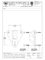
PARAMOUNT PATIO AWNING SPECIFICATIONS
The following information is for reference only. Specific information is detailed in the installation instructions.
L
ENGTH
14’ – 21’ (in 1 foot increments)
Position:
Slide-Out Window Patio
EXTENSION:
40" 72" 106"
LEAD RAIL DROP
8" (10°) 32" (33°) 51" (33°)
Values are approximate, actual dimensions may vary with specific installations.
Angles are measured from horizontal (parallel to ground)
MOTOR SPECIFICATIONS:
Available in LH or RH configurations
Type:
Tubular Motor
Power:
120V, 60HZ, 2.5A
Torque:
60 nm
Speed:
14 RPM
Cycle:
40 Sec ON / 1 Min OFF
CONTROLS:
Direct Response Electronics with a single master control and single remote for all awnings.
COLOR:
Hardware: White, Black
Fabric: Woven Acrylic Fabric
APPROXIMATE INSTALLED WEIGHT (LBS.)
Awning Length (ft.) Weight Awning Length (ft.) Weight Awning Length (ft.) Weight
14 206.5 17 229 20 251.5
15 214 18 236.5 21 259
16 221.5 19 244
7.13”
12.75”
A (Awning Length)
Paramount001
Top View
Profile

Carefree of Colorado Installation Manual PARAMOUNT
052548-001r11 2
COMPONENT CHECKLIST
6
1
2
7
9
20
22
23
24
25
8
5
43
10
11
13
12
14
15
18
16
19
17
21
Paramount002
Single Awning Electronics
Dual Awning Electronics
4-Awning Electronics
ON
OFF
26

Carefree of Colorado Installation Manual PARAMOUNT
052548-001r11 3
I
TEM DESCRIPTION QTY NOTE
1
Awning Assembly 1 1
2
Mounting Bracket 4 2
3
Screw, Thread Cutting 3/8 x 1 1/2 24
4
Screw, Hex Head 5/16-18 x 2 4
5
Square Nut 5/16-18 4
6
Hex Key 7mm x 133mm 1
7
Key Pad Switch Assy Single Awning 1 3,4
8
Control Box Single Awning 1 3
9
Screw #8 x 3/4 4
10
Remote Control, 433MHz Single Awning 1 3,5
11
Key Pad Switch Assy Dual Awning 1 3,4
12
Control Box Dual Awning 1 3
13
Screw #8 x 3/4 4
14
Remote Control, 433MHz Dual Awning 1 3,5
15
Key Pad Switch Assy 4-Awning Combo 1 3,4
16
Control Box, Box #1 4-Awning Combo 1 3
17
Control Box, Box #2 4-Awning Combo 1 3
18
Screw #8 x 3/4 8
19
Remote Control, 433MHz 4-AwningCombo 1 3,5
20
RF Receiver, 433MHz 1
21
Screw #6 x 1/2 2
22
RJ11 Cable 60 inches N
OTE 6
23
RJ11 Cable, used with items 11 & 15 20 feet 1
24
Sensor, Ignition Lock-Out 1 7
25
Splitter 1 7
26
Switch Kit w/ Fuse, LED Lighting
A/R 8
Notes: 1. Awning configuration is specified at time of order, including awning length, LH or RH
configuration, fabric color etc. Check awning assembly against original purchase order.
2. Quantity of 4 per awning is standard for item 2-mounting brackets. Some Original Equipment
Manufacturer (OEM) installations may specify a different quantity. Mounting brackets are
ordered separately and not included with awning.
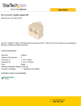
Two mounting plate kits are available. Flat
plates are used to mount to roofs with a 6˚
pitch. The 3˚ brackets are used with roofs with
a 3˚ pitch.
3. Electronic components are not interchangeable between systems.
4. Mounting screws are included with switches and switch plate.
5. Additional remotes can be ordered separately.
6. 60" cable (item 22) is furnished with items 7, 20 and 24 and one additional cable is furnished
with the 4-awning control boxes (items 16, 17).
7. The optional ignition lockout and splitter (items 24, 25) must be ordered separately.
8. The LED lighting switch kit (item 26) is optional and must be ordered separately.
6°
6°
3° Plate on a 3° Pitch RoofFlat Plate on a 6° Pitch Roof
Paramount033

Carefree of Colorado Installation Manual PARAMOUNT
052548-001r11 4
INSTALLATION – MECHANICAL
The following instructions are for the physical installation of one Paramount
awning. Repeat the instructions for each awning to be installed.
NOTE: When installing a multiple awning system, the awnings must be
separated by a minimum of 4".
REQUIRED PRE-INSTALLATION PARAMETERS
Prior to installing the awning system, the installer must determine the layout of the system and provide
specific construction elements to successfully assemble the awning components.
1. Determine the location, size and type of awning to be mounted.
There must be structure at the awning mount locations. Fiberglass or sheet metal alone is
NOT
strong enough to support the weight of the awning!
WARNING The Paramount awning has significant weight. The awning and attaching brackets
must be securely fastened to the structural frame of the roof. Consult the coach manufacturer to
determine the type and position of the roof's structural members and the structure's ability to support the
weight. Failure to heed this warning can result in serious injury and property damage.
2. Determine the mounting locations for the control box and switch assemblies.
For 110VAC installations, the installer must provide enclosed junction boxes for all wire splices. Boxes are
required in conformance with prevailing construction codes.
At the control box location, AC input is required. It is recommended that the installer provide a
dedicated AC circuit for the awning system that is protected by an appropriate sized fuse/circuit
breaker. Each patio awning draws a maximum of 3 amps.
The motion sensor for the Direct Response system is mounted on the patio awning. 10 feet cable is
available from the awning wall mount, and will require a routing path to the control box. If the control box is
located at a distance greater than 10 feet, the installer must provide a terminated jumper cable from the
box location to the cable end.
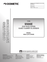
3. For installations over a slide-out room, an installer
furnished gutter is recommended between the awning
and room to prevent runoff spilling from under the
awning onto the top of the room.
4. For proper water runoff, the mounting plate must be
mounted a minimum 6˚ to the ground. If the coach
roof is not at the minimum angle, the installer must
furnish a mounting wedge bracket under the mounting
plate to achieve the correct angle.
5. For proper clearance above a slide-out room, the
leading edge of the mounting plate must be mounted
with the minimum height clearance value (H).
6. When a mounting bracket is used, it must be securely
fastened to the structural frame of the roof. The
installer must determine the correct screws to attach
the brackets.
7. For assistance in developing a suitable bracket,
contact the Carefree of Colorado engineering
department.
4” min.
Paramount027
Roof Line (ref)
Ground Level O
H
6º
Paramount026
4.25"
4 25"
3/8-16 x 1 1/2"
Thread Cutting Screw
5/16-18 x 2
Retaining Bolt & Square Nut
Directly Mounting to the Coach Roof
Installer Furnished
Rain Gutter
1" Minimum Depth
1" Area Cross Profile
6°
Top of Room Flange
H
Mounting with a Wedge Bracket
Extension 12" 18" 24" 30" 36"
H (min.) 5.25" 6.5" 7.5" 8" 8.25"

Carefree of Colorado Installation Manual P
ARAMOUNT
052548-001r11 5
M
OUNTING
P
LATE
L
AYOUT AND
I
NSTALLATION
The Paramount Patio Unit is mounted using four (4) 22” mounting brackets.
1. Determine the location of the awning mounts:
1.1 Mounting area must be flat and clear of obstacles,
1.2 The awnings have appreciable weight; the mounting screws
MUST fasten into the structure.
2. Position the mounting plates on the coach roof. Horizontally position the plates using the dimensions
in the chart. Use a chalk line or similar method to keep plates aligned.
3. Position a mounting plate and use the plate as a template to drill one 11/32” pilot hole into the
structure. Attach the plate using a 3/8-16 x 1 1/2 thread cutting screw.
4. Confirm position of plate and repeat step 3 on the opposite end of the mounting plate.
5. Continue to drill and attach using the 3/8-16 x 1 1/2 thread cutting screws for a minimum of6 mounting holes
per plate.
6. In the rear track of each mounting plate, start one (1) 5/16-18 screw and square nut through hole in back of
mounting plate. Do not tighten at this time.
7. At the motor location, drill one (1) 1/2” hole through outer surface. The position may be under or behind the
awning position.
M
OUNTING THE
A
WNING
U
NIT
CAUTION
The Apex awning is extremely heavy. Moving and/or lifting the awning
requires a minimum of 3 people. The use of a lifting device is strongly recommended.
1. While lifting the awning, route the awning motor wires through the 1/2” hole drilled previously.
NOTE: It is necessary to first insert the sensor cable and connector through the hole then insert the motor
wires.
2. Set the awning into the hooks of the mounting bracket. Pull
the case forward to fully engage the bracket.
3. Adjust the horizontal position of the awning as required.
Ensure that the brackets are located beneath the arm
case connectors.
4. Tighten the securing bolts. Torque to 10 ft-lbs.
5. Seal the wires and access hole with a quality silicone
sealant.
3” (typ)
A
3.7”
7.68”
8”
8” (typ)
9” (typ)
22”
B
C
L (Awning Length)
Paramount003
Top View
Mounting Plate Hole Pattern
D
L (feet) A (inches) B (inches) C (inches) D (inches)
14’ -- 16’11” 13” 55” L-55” L-13”
17’ -- 19’11” 14” 65” L-65” L-14”
20’ -- 21’ 25” 76” L-76” L-25”
Paramount004
5/16-18 x 2
Retaining Bolt
& Square Nut
(ref)
Mounting Bracket
(ref)

Carefree of Colorado Installation Manual P
ARAMOUNT
052548-001r11 6
INSTALLATION – ELECTRICAL
WARNING
Shock Hazard. Always disconnect battery or power source before
working on or around the electrical system.
IMPORTANT NOTICES:
Failure to follow the wiring instructions in this publication may void the warranty.
All wiring must conform to NEC (National Electrical Code) and local codes.
D
O NOT wire two or more motors to one motor controller.
The SO cable from the 110VAC awning motor can only pass directly through a wall, it can not be
laid up in the wall and must be connected to NM wire or individual wires in conduit no more than
6 inches past the point of entry.
The installer must provide enclosed junction boxes for all 110VAC wire splices. Boxes are
required in conformance with prevailing construction codes. Installers are required to furnish
the UL approved electrical boxes where required.
At the control box location, 110V power is required. It is recommended that the installer provide
a dedicated AC circuit for the awning system that is protected by an appropriate sized
fuse/circuit breaker. Each patio awning draws a maximum of 3 amps.
The motion sensor for the Direct Response system is mounted on the patio
awning. 10 feet of cable is available from the awning wall mount, and will
require a routing path to the control box. If the control box is located at a
distance greater than 10 feet, the installer must provide a terminated
jumper cable from the box location to the cable end.
Terminated cable is a 4-wire RJ11 terminated phone cord (straight, no
twist).
NOTE: Cable lengths of the furnished cables are listed in the chart with the
system wiring diagram. If a connection requires a length greater than the
supplied cable, the installer must provide a terminated cable from the box location
to the cable end.
K
EY
P
AD
I
NSTALLATION
1. Locate the mounting location of the key pad. The key pad
requires a flat area approximately 2 3/4" wide by 4 1/2" tall.
2. Use the mounting plate as a template and mark the
location of the two mounting holes.
3. Remove the plate, mark and cut a 1" hole in the position
shown.
4. Mount the plate to the surface using the included screws.
5. Route the 10 foot RJ11 cable from the control box location
through the wall and mounting plate.
6. Attach the cable to the back of the key pad then attach the
key pad to the mounting plate.
NOTE: The key pad attaches to the plate with magnetic
latches. No additional attaching hardware is required.
Black
Red
Green
Black
Yellow
Red
Green
Yellow
Cables are 4-wire RJ11
terminated phone cord
(straight, no twist).
RTA031
1.25”
O 1” min.
O .125” Pilot Hole
(2 plcs)
RJ11 Cable
Mounting Plate
Key Pad
Paramount005
4.5”
3.25”
(ref)
2.75”

Carefree of Colorado Installation Manual PARAMOUNT
052548-001r11 7
CONTROL BOX INSTALLATION
NOTE:
a) For Multiple Awning Installations: The awning motor connected to the controller board marked "motor #1" will
correspond with "Awning 1" on the key pad control and remote. The awning motor connected to "motor #2"
will correspond with "Awning 2" on the controls etc.
b) The control boxes are not suitable for exterior installations and must be mounted in the
INTERIOR of the
vehicle.
For Single Awning installations: refer to wiring diagram on page 8.
For 2- Awning installations: refer to wiring diagram on page 11.
For 4-Awning installations: refer to wiring diagram on page 13.
1. Locate the mounting location of the control
box(es). Each box requires a flat area
approximately 6 1/2" x 6 1/2" with a clearance depth
of 2 3/8".
For 4 awning installations: A 60" jumper cable is used
between the two control boxes. This allows
approximately 55" of cable between the boxes.
Position the boxes to allow the jumper to be connected
and routed with some slack in the cable.
2. Remove the lid. Attach the box to the mounting surface
using a minimum of two (2) #8 x 3/4 screws each. The
screws must be mounted in opposite corners.
3. Route a 2-conductor 14AWG NM wire with ground from the AC power source to the box. It is
recommended that the installer provide a dedicated AC circuit that is protected by an appropriate sized
fuse/circuit breaker. Each patio awning draws a maximum of 3 amps.
NOTE: Each board must have a 110VAC supply. The diagram shows a separate power source for each
box; each power source is spliced with wire nuts to power both boards in a box.
4. Connect the wires to the control box circuit boards as shown in the wiring diagram (Detail A).
5. Route the motor wires from awning #1 to controller #1 (motor#1); attach the wires to the terminals as shown.
NOTE: For LH motor configurations:
RED WIRE goes to terminal (1); BLACK WIRE goes to terminal (2).
For RH motor configurations:
RED WIRE goes to terminal (2); BLACK WIRE goes to terminal (1).
6. Attach the RJ11 cable from the sensor of awning #1 to the "AMD" receptacle of controller #1.
7. Repeat step 5 and 6 for the other awnings.
8. After testing connections, use Loctite 29005 or equivalent to secure screws in terminal block.
9. Attach the remaining RJ11 cables as shown in the wiring diagram. Use the slot cutouts in the box to
route the phone cables.
NOTE: The key pad and RF receiver only attach to controller #1.
#8 x 3/4 Screw (2)
RTA019c
6 1/2”
(typ)
2 3/8”

Carefree of Colorado Installation Manual PARAMOUNT
052548-001r11 8
INSTALLING THE REMOTE RECEIVER
1. Determine the location of the RF receiver:
1.1 Do not mount the unit near heat producing elements such as LP appliances or engine exhaust
components.
1.2 For best reception, do not mount the unit near or on a metal surface.
1.3 Mount the unit with the antenna pointing up.
1.4 The included cable is approximately 60 inches long.
Mount the unit close enough to the splitter or control
box so that the cord can be connected without
stressing the connections.
1.5 Allow adequate room below the box to access the
connector jack, programming button and indicator
light.
2. Position the control box and secure using two (2) #6 x 1/2” screws.
NOTE: If the box is mounted on a surface that is less than 1/2” thick, the screws will protrude through
the opposite side of the surface.
3. Connect the cable to the receiver.
4. Route the cable to the control box and connect to any open “EYE” port.
Programming the Receiver for the Remote
1. Power to the control box must be on.
2. Press and release the “Press to Learn Transmitter” button on the bottom
of the receiver box. The receiver is in program mode when the red light
comes on.
3. Press and release the
STOP button on the remote. The red light will go
out after the receiver learns the remote signal.
CAUTION When the receiver learns the transmitter signal, the
system will perform the operation of the button pressed. Example: Pressing
an "Extend" button during the learning phase will cause the awning to
extend when the receiver learns the signal. Use caution to avoid unexpected
movement by the awning.
4. Repeat steps 2 and 3 for each additional remote.
OPERATIONAL NOTES:
Transmitter and receiver operate on a frequency of 433MHz.
The receiver exits the program mode after ten seconds.
If the light does not come on in step 2, check the continuity of the cord between the boxes and repair or
replace as required. Pin 1 of the 1
st
connector goes to pin 1 of the 2
nd
connector etc. If the light still does not
come on, the memory is full and must be cleared.
If the light does not go out in step 3, the receiver already knows the transmitter's signal or the battery in
the remote needs to be replaced.
To clear the memory:
PRESS AND HOLD the transmitter learn button. While holding the button, the
indicator light should be OFF for the full 5 seconds then come on.
The system may be programmed for up to 5 remotes. Additional remotes may be ordered separately.
RTA034
1”
TO
EYE PORT
on RP24
Program
Mode
Press to Learn
Transmitter
UP
3 7/8”
4 3/16”
#6 x 1/2
Screw (2)
DR020
TO
EYE PORT
on RP24
Program
Mode
Press to Learn
Transmitter
UP
Program
Button
Indicator
Light

Carefree of Colorado Installation Manual PARAMOUNT
052548-001r11 9
IGNITION LOCKOUT SENSOR INSTALLATION (OPTIONAL)
Two ignition lockout sensors are available with the Direct Response System.
The STD ignition lockout module disables the extend function when the module receives a current
through a switched 12VDC circuit..
The RTL ignition lockout module will fully retract the awning and disable the extend function when the
module receives a current through a switched 12VDC circuit.
A switched 12VDC source is a line that is "hot" when the ignition switch is in the on position; or, a 12VDC
circuit through a relay that is "hot" when a specific condition is met (i.e. releasing the parking brake).
Relays are not furnished with this kit.
1. Disconnect power to the awning. Shut off the power source or pull the appropriate circuit breaker.
2. Locate the control box for the Direct Response System.
3. Open the cover of the control box.
4. For Single Awning Applications:
4.1. Disconnect the remote receiver cable from the "EYE" port in the control box. Do not disconnect the
cable from the receiver box.
4.2. Connect the supplied 6" cable to “EYE” port in the control box.
4.3. Attach the splitter to the other end of the cable.
4.4. Plug the cable from the remote receiver into the splitter.
4.5. Attach the Lock-Out Sensor to the end of the 60" cable. Route the cable as desired and connect
the cable to the splitter.
4.6. Proceed to step 6.
5. For Multiple Awning Applications:
5.1. The module may be connected to the control box as described for single awning applications.
OR
5.2. The module may be directly connected to any open "EYE" port on any of the control boards. It is
not necessary to use the short cable or splitter.
5.3. Proceed to step 6.
NOTE: Wires to the module are not pin specific.
6. Attach one 18-gauge wire to a terminal of the sensor and route the wire to a suitable 12VDC ground.
7. Attach a second 18-gauge wire to the second terminal of the sensor and route the wire to a SWITCHED
12VDC source.
8. Bundle and secure the sensor, cable and wires as required.
9. Reattach the control box cover.
10. Restore power to the awning.

Carefree of Colorado Installation Manual PARAMOUNT
052548-001r11 10
WIRING DIAGRAM – SINGLE AWNING
FROM TO (RH CONFIGURATION) TO (LH CONFIGURATION)
Motor Black Control Box
1
Control Box
2
Red
2 1
White 3 3
Ground 6 6
AC Power
Source
White Control Box 4 Control Box 4
Black 5 5
Ground 7 7
Awning Sensor 10’ Cable Control Box “AMD” Control Box “AMD”
Key Pad 60“ Cable Control Box “DSK” Control Box “DSK”
Splitter 60" Cable Control Box "EYE" Control Box "EYE"
RF Receiver 60” Cable Splitter "EYE" Splitter "EYE"
Ignition Lockout 60“ Cable Splitter "EYE" Splitter "EYE"
Notes: 1. Cable lengths are the lengths of the furnished cables. If a connection requires a length greater than the supplied cable, the
installer must provide a terminated jumper cable from the box location to the cable end.
2. Splitter is only required for single awnings only. RF Receiver and Ignition Lockout may be directly connected to any open
"EYE" port for multiple awning configurations.
TO
EYE PORT
on RP24
Program
Mode
Press to Learn
Transmitter
UP
RF
Receiver
GRN
BLK
WHT
RED
Key Pad
DR013
Ignition Switched
+12VDC
12VDC
Ground
Ignition
Lockout
Sensor
(Optional)
Splitter
Sensor
Key Pad
Awning #1
3
5
4
2 Conductor 14AWG
NM Wire w/ Gnd
To 110VAC
AMDSUNAUXEYEDSK
BLK
WHT
RED
GRN
grn
wht
blk
1
7
6
5
4
3
2
1
7
6
5
4
3
2
3 Conductor 14AWG
NM Wire w/ Gnd
Sensor
Remote
Red
Black
White
Green (Ground)
1
Wire Legend:
2
For LH Motor Configurations:
Motor Red goes to Pin (1); Motor Black goes to Pin (2)
For RH Motor Configurations:
Motor Red goes to Pin (2) Black; Motor Black goes to pin (1)
3
The SO cable from the 110VAC awning motor can only pass through a wall, it cannot be laid up in the wall
and must be connected to NM wire or individual wires in conduit no more than 6 inches past the point of entry.
NOTES:
4
Wires for the Ignition Lock-Out Sensor are not pin specific.
5
Splitter is used only when Optional Lock-Out Sensor is installed. Connect RF Receiver directly to “EYE”
if Lock-Out is not installed.
Detail A
For RH Configuration
Reverse Red & Black Wires
RED
WHT
BLK
GRN
grn
wht
blk

Carefree of Colorado Installation Manual PARAMOUNT
052548-001r11 11
WIRING DIAGRAM – 2-AWNINGS
TO
EYE PORT
on RP24
Program
Mode
Press to Learn
Transmitter
UP
RF
Receiver
GRN
BLK
WHT
RED
Key Pad
DR014a
Ignition Switched
+12VDC
12VDC
Ground
Ignition
Lockout
Sensor
(Optional)
Sensor #1
Key Pad
Sensor #2
Awning #1
3
5
RED
WHT
BLK
GRN
BLK
WHT
RED
GRN
Wht
Blk
Grn
Wht
Blk
Grn
2 Conductor 14AWG
NM Wire w/ Gnd
To 110VAC
AMDSUNAUXEYEDSK
AMDSUNAUXEYEDSK
1
7
6
5
4
3
2
1
7
6
5
4
3
2
1
7
6
5
4
3
2
3 Conductor 14AWG
NM Wire w/ Gnd
Sensor
GRN
BLK
WHT
RED
Awning #2
Sensor
Remote
3
3 Conductor 14AWG
NM Wire w/ Gnd
DETAIL
A
110VAC Power Line In
1
7
6
5
4
3
2
4
4

Carefree of Colorado Installation Manual PARAMOUNT
052548-001r11 12
FROM TO (MOTOR #1) TO (MOTOR #2)
AC Power Source White 4 4
Black 5 5
Ground 7 7
Awning #1 Motor Black
Refer to Flag Note 2
Red
White 3
Ground 6
Awning #2 Motor Black
Refer to Flag Note 2
Red
White 3
Ground 6
#1 Sensor 10’ Cable “AMD”
#2 Sensor 10’ Cable “AMD”
Key Pad 25' Cable DSK
RF Receiver 60” Cable "EYE" see note 4
Ignition Lockout 60“ Cable "EYE" see note 4
Green (Ground)
White
Red
Black
1
Wire Legend:
2
Awnings #1 & #4 shown as LH Motor, Awnings #2 & #3 shown as RH Motor
For LH Motor Configurations:
Motor Red goes to Pin (1); Motor Black goes to Pin (2)
For RH Motor Configurations:
Motor Red goes to Pin (2); Motor Black goes to pin (1)
3
The SO cable from the 110VAC awning motor can only pass directly through a wall, it cannot be laid up
in the wall and must be connected to NM wire or individual wires in conduit no more than 6 inches past
the point of entry.
NOTES:
4
DR016a
5
Wires for the Ignition Lock-Out Sensor are not pin specific.
The RF Reciever and the optional Ignition Lockout may be plugged into any open “EYE” port.
7
6
Cables are 4-wire RJ11 terminated phone cord (straight, no twist)
For screw type terminals: After testing connections, use Loctite 29005 or equivalent
to secure screws in terminal block.
8
Terminal block designations are for reference only. Actual boards may not be marked.
Loctite
29005
Screw Type
Terminal Block

Carefree of Colorado Installation Manual PARAMOUNT
052548-001r11 13
WIRING DIAGRAM – 4 AWNINGS
TO
EYE PORT
on RP24
Program
Mode
Press to Learn
Transmitter
UP
RF
Receiver
GRN
BLK
WHT
RED
Key Pad
DR015a
Sensor #1
Key Pad
Sensor #2
Awning #1
3
4
4
RED
WHT
BLK
GRN
BLK
WHT
RED
GRN
Wht
Blk
Grn
Wht
Blk
Grn
2 Conductor 14AWG
NM Wire w/ Gnd
To 110VAC
RED
WHT
BLK
GRN
BLK
WHT
RED
GRN
AMDSUNAUXEYEDSK
AMDSUNAUXEYEDSK
AMDSUNAUXEYEDSK
AMDSUNAUXEYEDSK
1
7
6
5
4
3
2
1
7
6
5
4
3
2
1
7
6
5
4
3
2
1
7
6
5
4
3
2
1
7
6
5
4
3
2
To 110VAC
3 Conductor 14AWG
NM Wire w/ Gnd
To 110VAC
Sensor
GRN
BLK
WHT
RED
Awning #2
Sensor
Remote
3
3 Conductor 14AWG
NM Wire w/ Gnd
GRN
BLK
WHT
RED
Sensor #3
Sensor #4
Awning #3
3
3 Conductor 14AWG
NM Wire w/ Gnd
Sensor
GRN
BLK
WHT
RED
Awning #4
Sensor
3
3 Conductor 14AWG
NM Wire w/ Gnd
DETAIL
A
110VAC Power Line In
(typical both boxes)
1
7
6
5
4
3
2
Ignition Switched
+12VDC
12VDC
Ground
Ignition
Lockout
Sensor
(Optional)
5

Carefree of Colorado Installation Manual PARAMOUNT
052548-001r11 14
TO CONTROL BOARD
FROM MOTOR #1 MOTOR #2 MOTOR #3 MOTOR #4
AC Power Source White 4 4 4 4
Black 5 5 5 5
Ground 7 7 7 7
Awning #1 Motor Black
Refer to Flag
Note 2
Red
White 3
Ground 6
Awning #2 Motor Black
Refer to Flag
Note 2
Red
White 3
Ground 6
Awning #3 Motor Black
Refer to Flag
Note 2
Red
White 3
Ground 6
Awning #4 Motor Black
Refer to Flag
Note 2
Red
White 3
Ground 6
#1 Sensor 10’ Cable “AMD”
#2 Sensor 10’ Cable “AMD”
#3 Sensor 10’ Cable “AMD”
#4 Sensor 10’ Cable “AMD”
Key Pad 25' Cable "DSK"
RF Receiver 60” Cable "EYE" see note 4
Ignition Lockout 60“ Cable "EYE" see note 4
Notes: 1. Splitter is used w/ Ignition Lock-Out only. If Lock-Out is not installed, connect the receiver directly to "EYE".
2. Cable lengths are the lengths of the furnished cables. If a connection requires a length greater than the supplied cable, the
installer must provide a terminated jumper cable from the box location to the cable end.
Green (Ground)
White
Red
Black
1
Wire Legend:
2
Awnings #1 & #4 shown as LH Motor, Awnings #2 & #3 shown as RH Motor
For LH Motor Configurations:
Motor Red goes to Pin (1); Motor Black goes to Pin (2)
For RH Motor Configurations:
Motor Red goes to Pin (2); Motor Black goes to pin (1)
3
The SO cable from the 110VAC awning motor can only pass directly through a wall, it cannot be laid up
in the wall and must be connected to NM wire or individual wires in conduit no more than 6 inches past
the point of entry.
NOTES:
4
DR016a
5
Wires for the Ignition Lock-Out Sensor are not pin specific.
The RF Reciever and the optional Ignition Lockout may be plugged into any open “EYE” port.
7
6
Cables are 4-wire RJ11 terminated phone cord (straight, no twist)
For screw type terminals: After testing connections, use Loctite 29005 or equivalent
to secure screws in terminal block.
8
Terminal block designations are for reference only. Actual boards may not be marked.
Loctite
29005
Screw Type
Terminal Block

Carefree of Colorado Installation Manual PARAMOUNT
052548-001r11 15
CONNECTION FLEX W/ "110VDR" CONTROL BOXES
The wiring diagrams show the standard installation for multiple awning configurations. For control boxes marked
w/ "110VDR", the installer may adjust the cable interconnections for greater flexibility during installation.
1. The key pad may be installed in the unused DSK port of any board with the jumper cables sequentially
connected from the AUX port to the DSK port of the next board.
Example: Placing the keypad in the DSK of Board 3.
2. The RF Receiver and the optional ignition lock-out can be plugged into any unused "EYE" port. It is not
necessary to use the splitter as shown in the diagrams.
3. The "110VDR" control boxes are compatible with integrator interfaces. Contact Carefree engineering
for information and system requirements.
OPTIONAL MANUAL BYPASS SWITCH
Installers may elect to install a manual bypass switch for testing or
emergency operation of the awning. The simple switch allows the
operator to extend or retract the awning without using the keypad
control panel. For multiple awning installations, a separate switch
must be installed for each awning.
1. Open the control box and identify the terminal block next to
the phone cord jacks.
2. Connect the switch to the terminal block as shown in the
diagram.
The switch is a single pole, double throw, momentary ON, center
OFF. Components are installer furnished.
Key Pad
CR024
AMDSUNAUXEYEDSK
AMDSUNAUXEYEDSK
AMDSUNAUXEYEDSK
AMDSUNAUXEYEDSK
Motor 1 Motor 2 Motor 3 Motor 4
Common
Extend
Retract
Manual Switch
Single Pole, Double
Throw, Momentary ON,
Center OFF
DR011

Carefree of Colorado Installation Manual PARAMOUNT
052548-001r11 16
SWITCH INSTALLATION - LED LIGHTING
Optional factory installed LED light strips are available for the Paramount awning. A strip can be mounted
in the lead rail or in the case or both. For lead rail installations, the harness is routed through the awning
with the Direct Response cable.
Each LED strip may be attached to an individual switch or two LED strips can be hooked in parallel to a
single switch.
NOTE: Installers may choose to furnish the control switch. The installation requires that the power line
(+12VDC) be attached to a dedicated 2A circuit breaker; or, a 2A in-line fuse must be installed between
each switch and power source. For easy access, locate the fuse close to the switch.
1. Route the harness into the vehicle with
the Direct Response cable and the
motor power cable.
2. Determine the location of the switch.
3. At the switch location, cut a 1 1/8" x 1
1/2" hole.
4. Wire the switch as shown below. Wire
terminals at the switch are .187, 18-24
awg female disconnects.
NOTE: Allow adequate slack in the
12VDC power line so that the in-line
fuse (installed in step 4) can be
accessed from behind the switch.
5. Install the in-line fuse:
5.1. Near the switch, cut the red 12VDC
power line to the switch. Do not
strip the insulation.
5.2. Insert a wire end into one of the
wire channels until it butts up
against the stop.
5.3. Fold that half of the connector body
over until the element contacts the
wire. Use pliers to crimp the
connector closed.
5.4. Repeat for the second wire end.
5.5. Slide the fuse into the fuse port.
Ensure that is firmly seated.
6. Press the in-line fuse, wires and switch
into the mounting hole. Secure the
switch using two (2) #6 x 1/2" screws.
7. Snap the switch bezel over the switch
frame.
LED002d
Vehicle Wall
Red
+12VDC
GND
Single Pole
Single Throw Switch
18awg Wire
(minimum)
Connector
LED Strip in Lead Rail or Case
Red
Black
18-24awg
Female Disconnect (x2)
ON
OFF
1.13"
1.5"
1.88"
2.9"
#6 x 1/2” Screw (x2)
2A In-line Fuse
2A In-line Fuse
(+12VDC Line)
Vehicle Wall
Red
+12VDC
GND
Single Pole
Single Throw Switch
18awg Wire
(minimum)
Connector
LED Strip in Lead Rail
Red
Black
18-24awg
Female Disconnect (x2)
2A In-line Fuse
Connector
LED Strip in Case
Red
Black
Individual Strip
Double Strip

Carefree of Colorado Installation Manual PARAMOUNT
052548-001r11 17
TESTING THE SYSTEM
All function buttons are press ON. The auto-functions continue until the awning is fully extended or
retracted. Pressing the button a second time will stop the function (does not apply to the "Extend All" or
Retract All" commands). It is not necessary to hold the button while the function is active.
1. While observing the control panel, have a second person initiate 110VAC power to the coach and
awning system. The following should occur:
1.1 The System Indicator and Sensitivity Level LEDs will briefly illuminate.
1.2 The system then goes to the default settings: The default settings are the last known state when
the AC power source was suspended. Example: If power was "ON" and the sensitivity was set to
"2", when AC power is applied, power will be on and sensitivity will be set to "2".
2. If ON, press the P
OWER “OFF”. ALL LEDs should be extinguished. The POWER ON/OFF button disables all
functions including Auto-Retract and the RF remote. It does not disconnect the 110VAC power.
NOTE: If the awning moves opposite the label markings, the red and black
MOTOR wires are reversed
in the control box.
3. Check the extend function.
3.1 Press the POWER “ON.
3.2 Press the Awning #1 E
XTEND button. The awning should extend.
3.3 Press the extend button again. The awning should stop
3.4 Press the extend button a third time. Observe the awning, it should fully extend. The system performs
an auto-tension action when the awning is fully extended. The awning rolls in reverse to tension the
fabric. The auto-tension feature works only with the extend function when the awning is fully extended.
4. Check the retract function.
4.1 Press the Awning #1 R
ETRACT button. The awning should retract.
4.2 Press the retract button again. The awning should stop
4.3 Press the retract button a third time. Observe the awning; it should fully retract to the closed position.
NOTE: It is normal for the lead rail to slightly relax after the awning closes completely.
5. Repeat steps 3 and 4 for each of the Extend/Retract button combinations.
6. Test the mid-position functions. Press and release each mid position button (Slide-Out cover and Window).
The awning should extend or retract to the specified position.
7. Test the Auto-Retract function:
8.1 Fully extend awning #1.
8.2 Set the W
IND SPEED to the lowest setting.
8.3 Create a firm but gentle vertical rocking motion with the leading edge of the awning. The awning should
retract after 2-3 seconds of the motion. The awning will retract to the slide-out position.
8. Repeat step 6 for each of the awnings.
9. If the optional Ignition Sensor is installed:
10.1 Partially retract the awning.
10.2 Turn the vehicle ignition key ON.
10.3 If the RTL lockout is installed, the awning(s) will retract.
10.4 Press the E
XTEND button. The awning(s) should not extend.

Carefree of Colorado Installation Manual PARAMOUNT
052548-001r11 18
STANDARD SYSTEM ADJUSTMENTS
AWNING CALIBRATION PROCEDURE
For multiple awning installations, if the awnings do not align at the intermediate positions (slide-out and
window), it is necessary to run a calibration routine to adjust the run and stop times for the awning.
1. The controls are programmed with default awning calibration values; this allows full awning operation
out-of-the-box.
2. The default calibration values are based on the average run times for the Paramount awning; these
values are close but not perfect.
3. The Slide-Out Cover and Window awning intermediate positions are set as a percentage of the awning
run time, 29% for Slide-Out Cover and 70% for Window.
4. Performing an awning calibration collects the actual extend and retract run times to allow the most
accurate awning operation.
5. For multiple awning installations, adjacent awnings must be aligned in the full extension position before
initiating awning calibrations, otherwise, a calibration will lock-in the difference in run times and will
cause misalignment at the intermediate positions.
6. For multiple awning installations, it is recommended that all awnings be calibrated at the same time
while operating on the same power source, i.e. do not calibrate one awning while operating on the
inverter and another while operating on the generator.
7. If a calibration is started and fails (stops) for any reason, the system resets the travel time and
maximum run time to the default values.
Procedure
Prior to starting the procedure, ensure that the motor limits are set correctly (refer to page 20).
The IN limit switch must be set to allow the motor to stall. Calibration will fail if the switch is set to stop
the motor.
The OUT limit switch is used to align adjacent awnings in the fully extended position before initiating
awning calibrations, otherwise, a calibration will lock-in the difference in run times and will cause
misalignment at the intermediate positions.
NOTICE Do not continuously operate the awning more than 2-3 cycles maximum. The motor is
equipped with a thermal protection circuit to protect the motor from overheating. Operating the awning
repeatedly over a short time period may cause the circuit to sense an overheat condition and shut off the
motor. If this occurs, wait approximately 15 minutes to allow the motor to cool then resume the
procedure.
/