Page is loading ...

ENSURE THAT THESE
INSTRUCTIONS ARE LEFT
FOR THE USER AFTER
COMPLETION OF THE
BENCHMARK SECTION
PLEASE READ THE
IMPORTANT NOTICE
WITHIN THIS GUIDE
REGARDING YOUR BOILER
WARRANTY
USER, INSTALLATION AND SERVICING INSTRUCTIONS
MURELLE
HE 35 R ErP
Cod. 6322810B - 09/2018
199839
ORIGINAL INSTRUCTIONS

All descriptions and illustrations provided in this manual have been carefully prepared but we reserve the right to make changes and
improvements in our products that may affect the accuracy of the information contained in this manual.
This boiler may require 2 or more operatives to move it into its installation site, remove it from its packaging and
during movement into its installation location. Manoeuvring the boiler may include the use of a sack truck and
involve lifting pushing and pulling.
Caution should be exercised during these operations.
Operatives should be knowledgeable in handling techniques when performing these tasks and the following pre-
cautions should be considered:
– Grip the boiler at the base
– Be physically capable
– Use personal protective equipment as appropriate e.g. gloves, safety footwear.
During all manoeuvres and handling actions, every attempt should be made to ensure the following unless unavoi-
dable and/or the weight is light.
– Keep back straight
– Avoid twisting at the waist
– Always grip with the palm of the hand
– Keep load as close to the body as possible
– Always use assistance
WARNING
Caution should be exercised when performing any work on this appliance.
Protective gloves and safety glasses are recommended.
– Avoid direct contact with sharp edges.
– Avoid contact with any hot surfaces.
NOTICE
Please be aware that due to the wet testing of the appliance, there may some residual water in the hydraulic cir-
cuit.
– Protect any surfaces, carpets or floorings.
– Use a suitable container to catch any water that escape when removing the protective caps from the connec-
tions.
SAFE HANDLING
IMPORTANT NOTICE
For the first year all of our appliances are protected by our manufacturer’s guarantee which covers both
parts and labour.
As you would expect from Sime Ltd, it is our aim to provide our valued customers with the best in after sales
and service.
To take advantage of any extended warranty offered, all you have to do is to adhere to these 3 simple condi-
tions:
• The installation must be carried out to Manufacturers Standards by a Gas Safe Registered Engineer, and
recorded in the installation manual.
• The appliance must be registered with both Sime Ltd and Gas Safe within 30 days of installation.
• The appliance must be serviced every 12 months, within 30 days of the anniversary of the installation date,
by either Sime Ltd or a Gas Safe registered engineer- ensuring that the Benchmark service record in the
installation manual is completed.
Failure to comply with the above will result in only the 12 month warranty being offered.
In the absence of any proof of purchase, the 12 month warranty period will commence from the date of manu-
facture of the boiler as shown on the appliance data plate.


IMPORTANT INFORMATION
IT IS A STATUTORY REQUIREMENT THAT ALL GAS APPLIANCES ARE INSTALLED BY COMPETENT PERSONS, IN
ACCORDANCE WITH THE GAS SAFETY (INSTALLATION AND USE) REGULATIONS (CURRENT EDITION).
The manufacturer’s instructions must not be taken as overriding any statutory requirements, and failure to comply with
these regulations may lead to prosecution.
No modifications to the appliance should be made unless they are fully approved by the manufacturer.
GAS LEAKS: DO NOT OPERATE ANY ELECTRICAL SWITCH, OR USE A NAKED FLAME. TURN OFF THE GAS SUPPLY AND
VENTILATE THE AREA BY OPENING DOORS AND WINDOWS contact the gas emergency service on 0800111999.
Murelle HE 35 R ErP: Gas Council number 41-283-59
The Benchmark Scheme
Sime Ltd is a licensed member of the Benchmark Scheme which aims to improve the standards of installation
and commissioning of domestic heating and hot water systems in the UK and to encourage regular servicing
to optimisesafety, efficiency and performance.
Benchmark is managed and promoted by the Heating and Hotwater Industry Council.
For more information visit www.centralheating.co.uk.
Please ensure that the installer has fully completed the Benchmark Checklist in the use and maintenance
section of the installation instructions supplied with the product and that you have signed it to say that you
have received a full and clear explanation of its operation.
The installer is legally required to complete a commissioning checklist as a means of complyng with the
appropriate Building Regulations (England and Wales).
All installations must be notified to Local Area Building Control either directly or through a Competent
Persons Scheme.
A Building Regulations Compliance Certificate will then be issued to the customer who should, on receipt,
write the Notification Number on the Benchmark Checklist.
This product should be serviced regularly to optimise its safety, efficiency and performance.
The service engineer should complete the relevant Service Record on the Benchmark Checklist after each
service.The Benchmark Checklist may be required in the event of any warranty work and as supporting docu-
mentation relating to home improvements in the optional documents section of the Home Information Pack.
CONFORMITY
Our Company declares that MURELLE HE 35 R ErP boilers comply with the essential requirements of the following
directives:
- Boiler Efficiency Directive 92/42/EEC
- Gas Regulation 2016/426/EC
- Electromagnetic Compatibility Directive 2014/30/UE
- Low Voltage Directive 2014/35/UE
- Ecodesign Directive 2009/125/EC
- Regulation (EU) N. 813/2013 - 811/2013
- Energy Labelling 2010/30/CE

CONTENTS
1 DESCRIPTION OF THE BOILER ...................................................................................................................... pag. 6
2 INSTALLATION ............................................................................................................................................... pag. 10
3 CHARACTERISTICS ........................................................................................................................................ pag. 28
4 USE AND MAINTENANCE, BENCHMARK AND COMMISSIONING ................................................................ pag. 35
5 FAULT FINDING ............................................................................................................................................. pag. 47
6 REPLACEMENT OF PARTS ............................................................................................................................ pag. 48
7 EXPLODED VIEWS .......................................................................................................................................... pag. 49
8 APPENDIX 1 ................................................................................................................................................... pag. 54
USER INSTRUCTIONS .................................................................................................................................... pag. 66
PRODUCT DETAILS ........................................................................................................................................ pag. 68
ANNEX AA.1 ................................................................................................................................................... pag. 69
IMPORTANT
When carrying out commissioning of the boiler, you are highly recommended to perform the following
checks:
– Make sure that there are no liquids or inflammable materials in the immediate vicinity of the boiler.
– Make sure that the electrical connections have been made correctly and that the earth wire is con-
nected to a good earthing system.
– Open the gas valve and check the soundness of the connections, including that of the burner.
– Make sure that the boiler is set for operation for the type of gas supplied.
– Check that the flue pipe for the outlet of the products of the combustion is unobstructed and has been
properly installed.
– Make sure that any shutoff valves are open.
– Make sure that the system is charged with water and is thoroughly vented.
– Check that the circulating pump is not jammed.
– Purge the system, bleeding off the air present in the gas pipe by operating the pressure relief valve on
the gas valve inlet.
– Complete the checklist included in this manual.
Please refer to commissioning instructions for filling in the checklist at the back of this installation guide.
Note: All Gas Safe registered installers carry a ID Card.
You can check your installer is Gas Safe Registered by calling 0800 408 5577
VERY IMPORTANT!
PLEASE MAKE SURE YOUR COMMISSIONING CHECKLIST AND THE SERVICE INTERVAL RECORDS
ENCLOSED FILLED IN CORRECTLY.
ALL GAS SAFE REGISTERED INSTALLERS CARRY A GAS SAFE ID CARD.
BOTH SHOULD BE RECORDED IN YOUR COMMISSIONING CHECKLIST AND A SERVICE INTERVAL RECORDS.
YOU CAN CHECK YOUR INSTALLER IS GAS SAFE REGISTEREDBY CALLING
ON 0800 408 5500 OR ALTERNATIVELY WWW.GASSAFEREGISTER.CO.UK

6
1.1 INTRODUCTION
MURELLE HM 35 R ErP are premixed gas
condensing boilers for heating only with
wide range of power modulation (from
20% to 100% of power) designed for sin-
gle installation and in modular systems
with multiple generators connected in
sequence/cascade and independent
from each other. For optimum instal-
lation and operation, always follow the
instructions provided in this manual.
1 DESCRIPTION OF THE BOILER
100
130
95
450
95
168
350
90
701
130
44
124
M
S3 G
R
MG R
S3
CS
CA
Fig. 1
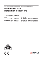
FIXTURES
R Heating return G 3/4” (UNI - ISO 228/1)
M Heating flow G 3/4” (UNI - ISO 228/1)
G Gas connection G 3/4” (UNI - ISO 228/1)
S3 Condensation outlet ø 25
CA Air inlet ø 80
CS Exhaust ø 80
1.2 DIMENSIONS (fig. 1)

7
MURELLE HE 35 R ErP
Heat output nominal (80-60°C) (Pn max) kW 33.8
Heat output nominal (50-30°C) (Pn max) kW 37.2
Heat output reduced G20 (80-60°C) (Pn min) kW 3.2
Heat output reduced G20 (50-30°C) (Pn min) kW 3.7
Heat output reduced G31 (80-60°C) (Pn min) kW 5.5
Heat output reduced G31 (50-30°C) (Pn min) kW 6.4
Heat input (*)
Nominal (Qn max - Qnw max) kW 34.8
Reduced G20/G31 (Qn min - Qnw min) kW 3.48 / 6.0
Min/max useful yield (80-60°C) % 92.0 / 97.1
Min/max useful yield (50-30°C) % 106.3 / 106.8
Useful yield at 30% of the load (40-30°C) % 108,6
Losses after shutdown to 50°C (EN 15502) W 108
Supply voltage V-Hz 230-50
Adsorbed power consumption (Qn max - Qn min) W 109 - 66
Electrical protection grade IP X4D
Energy efficiency
Seasonal energy efficiency class of the heating system A
Seasonal energy efficiency of the heating system % 93
Sound power of the heating system dB (A) 56
C.H. setting range °C 20/80
Water content boiler l 2.65
Maximum water head (PMS) bar (kPa) 3.5 (343)
Maximum temperature (T max) °C 85
Capacity of the heating expansion vessel l --
Pressure of the heating expansion vessel bar (kPa) --
Exhaust fumes temperature at max flow rate (80-60°C) °C 70
Exhaust fumes temperature at min. flow rate (80-60°C) °C 60
Exhaust fumes temperature at max flow rate (50-30°C) °C 40
Exhaust fumes temperature at min. flow rate (50-30°C) °C 33
Smokes flow min/max g/s 1.67 / 16.39
CO
2 at max/min flow rate (G20) % 8.4 / 9.3
CO
2 at max/min flow rate (G31) % 10.0 / 10.2
NOx measured (EN 15502-1:2015) mg/kWh 21
PIN number 1312CM5630
Category II2H3P
Type B23P-B53P-C13-C33-C43-C53-C83
NOx emission class (EN 15502-1:2015) 6 (< 56 mg/kWh)
Weight when empty kg 32
Main burner nozzle
Quantity nozzles n° 2
G20 nozzle diameter diversified ø 3.5 / 4.0
G31 nozzle diameter diversified ø 2.8 / 3.0
Consumption at maximum/minimum flow rate
Maximum (G20) m
3
/h 3.68
Minimum (G20) m
3
/h 0.39
Maximum (G31) kg/h 2.70
Minimum (G31) kg/h 0.46
Gas supply pressure
(G20/G31) mbar (kPa) 20 / 37 (1.96 / 3.63)
(*) Heat input of the heating system measured using lower heating value (LHV)
1.3 TECHNICAL FEATURES

8
1.4 FUNCTIONAL DIAGRAM (fig. 2)
Fig. 2
KEY
1 Fan
2 Exhaust temperature sensor (SE)
4 Heating flow sensor (SM)
5 Gas valve
6 Safety thermostat 100°C
7 Aqua Guard Filter System
10 Pump high efficiency
11 Heating return sensor (SR)
13 Condensate drain trap
14 Safety valve 3 bar
15 Water pressure transducer
16 Boiler discharge
17 Primary heat exchanger
CONNECTIONS
R Heating return
M Heating flow
G Gas connection
S3 Condensation outlet
17

9
1
2
3
4
5
6
7
8
9
10
12
11
13
14
Fig. 3
1.5 MAIN COMPONENTS (fig. 3)
KEY
1 Control panel
2 Aqua Guard Filter System
3 Condensate drain trap
4
Heating flow sensor (SM)
5 Safety thermostat
6 Ignition electrode
7 Primary heat exchanger
8 Limit thermostat
9 Exaust probe (SF)
10 Detection electrode
11 Fan
12 Return heating probe (SR)
13 Automatic air vent
14 Pump high efficiency
Fig. 3/a
1.6 TECHNICAL DATA PLATE (fig. 3/a)
MODEL
SERIAL NUMBER
YEAR OF CONSTRUCTION
WATER CONTENT IN BOILER
HEAT INPUT MAX
HEAT OUTPUT MAX (80-60°C)
HEAT OUTPUT MAX (50-30°C)
MAX OPERATING PRESSURE
CONTENTS D.H.W.
HEAT INPUT MAX D.H.W.
MAX OPERATING PRESSURE D.H.W.
D.H.W. FLOW RATE
POWER SUPPLY
MAX POWER ABSORBED
COUNTRIES OF DESTINATION
CATEGORY
TYPE
CODE
DIRECTIVE OF REFERENCE
PIN NUMBER
HEAT INPUT MIN
HEAT OUTPUT MIN (80-60°C)
HEAT OUTPUT MIN (50-30°C)
MAX OPERATING PRESSURE
HEAT INPUT MIN D.H.W.
MAX OPERATING PRESSURE D.H.W.
ELECTRICAL PROTECTION GRADE
NOx CLASS
CODE GAS COUNCIL NUMBER (UK)
CERTIFICATION WRAS (UK)
TYPE OF GAS
GAS SUPPLY PRESSURE
CLASSIFICATIONS

10
R
M
M2
R3
170
140
60
330
123
123
450
340
701
262
564
R
M
M2
R3
170
140
60
330
123
123
450
340
701
262
564
MURELLE HE 35 R UK
MURELLE HE 35 R
The boiler must be installed in a fixed
location and only by qualified engineers
in compliance with all instructions con-
tained in this manual.
Furthermore, the installation must be in
accordance with current standards and
regulations.
CAUTION: Before assembling the
appliance, the installer MUST make
sure that the wall supports the weight.
2.1 VENTILATION
MURELLE HE 35 R ErP can be installed
in boiler rooms whose size and require-
ments meet current regulations.
VENTILATION
The following is provide for your guidan-
ce only, and assumes the ventilation air
is taken directly from outside.
The sizes of the vents may need to be
increased in respect of other appliances
installed in the same area, and seasonal
use.
Take care that the position of low level
vents would not subject to adverse wea-
ther conditions, ie flooding.
Ventilation requirements
for Murelle HE 35 R (M) boilers
and cascade systems.
BS6644 has a requirement that the tem-
peratures in a room or compartment do
not exceed certain levels:
- 25°C at floor level(0-100mm)
- 32°C at mid level (1.5M above the floor
level)
- 40° C at ceiling level (0-100mm from
ceiling)
When installed as a class B appliance
(open flued, not roomed sealed).
Installed in a room
High level (within 15% of the room height
from ceiling) - 2cm²/KW of net heat
input
Low level (low as possible within 1 metre
from floor natural gas, 250mm LPG)–
4cm²/KW of net heat input
A single Murelle HE 35 R ErP (34.8 KW
net input) boiler would require 70 cm² at
high level and 140 cm² at low level.
Installed in a compartment or enclosure
High level (within 15% of the room height
from ceiling) - 5 cm²/KW of net heat input
Low level (low as possible within 1 metre
2 INSTALLATION
Fig. 4
M C.H. flow
R 2” (UNI-ISO 7/1)
R C.H. return
R 2” (UNI-ISO 7/1)
M2 D.H.W. tank flow
G 3/4” (UNI-ISO 228/1)
R3 D.H.W. tank return
G 3/4” (UNI-ISO 228/1)
Single installation
with kit optional code 8101585
WARNING:
- It is mandatory to arrange the
thermal system with the hydrau-
lic separator.
- When replacing one or more
boilers in existing plants, it is ad-
visable to install a heat exchan-
ger to separate the boiler circuit
from the secondary circuits. See
the pressure curve for the boiler
supply shown in figure 14.

11
from floor natural gas, 250 mm LPG) – 10
cm²/KW of net heat input.
A single Murelle HE 35 R ErP (34,8 KW
net input) boiler would require 174 cm² at
high level and 348 cm² at low level.
When installed as a class C
appliance(room sealed)
Installed in a room
High level (within 15% of the room height
from ceiling) - 2cm²/KW of net heat
input
Low level (low as possible within 1 metre
from floor natural gas, 250mm LPG)–
2cm²/KW of net heat input
A single Murelle HE 35 R ErP (34,8 KW
net input) boiler would require 70 cm² at
high level and 70 cm² at low level.
Installed in a compartment or enclosure
High level (within 15% of the room height
from ceiling) - 5cm²/KW of net heat
input
Low level (low as possible within 1 metre
from floor natural gas, 250mm LPG)–
5cm²/KW of net heat input.
A single Murelle HE 35 R ErP (34,8 KW
net input) boiler would require 174 cm² at
high level and 174 cm² at low level.
2.2 INSTALLATION
2.2.1 Single boiler (fig. 4)
For single boiler installations a kit is
available upon request: cod. 8101585.
The boiler is supplied as a Class b
device(open flued), it can be converted
to a Class C device (room sealed), see
section 2.5.
The system head available is shown in
section 3.8.
If the connected system incorporates
additional pumps, then a hydraulic sepa-
rator must be installed. if the boiler is to
be installed in an existing system then
consideration must be made for the use
of a plate heat exchanger..
2.2.2 Sequence/cascade boilers
(fig. 4 - fig. 4/a)
Attention
In sequence or cascade installations the
use of a hydraulic separator is manda-
tory.
When boilers are connected to a com-
mon cascade flue(incorporating a cla-
pet valve), each boiler connected to the
common flue must have PAR 1 reset as
follows:
- PAR 1 = 6 (for G20 NATURAL GAS boi-
lers)
- PAR 1 = 14 (for G31 PROPANE boilers)
Refer to section 3.3 to access the
INSTALLER PARAMETERS section.
The boiler is supplied with RS-485 that
board that allows management of up to
8 boilers in cascade and communication
in MODBUS. The board is placed on the
back of the control panel. Access the
board and select the desired operating
mode (CASCADE or MODBUS) by selec-
ting the DIP SWITCH of the board as
indicated in figure 4/a.
CASCADE mode (fig. 4/b)
Electrically connect all the boilers
in CASCADE mode and set PAR 15
accordingly(master or slave), as shown
in fig 4/b.
CASCADE WITH MORE
THAN TWO BOILERS
When more than two boilers are connected
in cascade, it is essential that the OEM
parameter on the “Master” boiler is reset
to coincide with the number of boilers in
the cascade.
This must be done after setting PAR 15 on
the designated Master boiler to “0”
On the “Master” boiler press any key to
wake up the display.
Then press simultaneously the and
the buttons for 5 seconds until the
display is as shown.
Then press again, simultaneously, the
and the buttons for 2 seconds until
the display shows.
Next press, in the order shown
The display will be as shown.
Press the
button, and the display
will show.
Use the
and buttons to set the
number of boilers in the cascade.
Then press
to confirm the settings.
DIP SWITCH
GESTIONE IN CASCATA
1
2 3
CASCADE MANAGEMENT
DIP SWITCH
GESTIONE IN MODBUS
MODBUS MANAGEMENT
1
23
ON
1
23
ON
x 2
CN10
CHIAVE
POLARIZATION
Fig. 4/a

12
DIP SWITCH
DIP SWITCH
DIP SWITCH
1
2
3
1
2
345
6
1
2
345
6
1
2
345
6
X5
X5
WIRED
CONNECTOR
CN10
(code 6319165)
RS-485 BOARD
RS-485 BOARD
RS-485 BOARD
WIRED
CONNECTOR
CN10
(code 6319165)
WIRED
CONNECTOR
CN10
(code 6319165)
BOILER BOARD (SLAVE ...)
BOILER BOARD (SLAVE 1)BOILER BOARD (MASTER)
ON
1
2
3
ON
1
2
3
ON
EXTERNAL
SENSOR (SE)
CASCADE SUPPLY PROBE (SMC)
CHARACTERISTICS
OF ELECTRIC CABLE:
-
3 wires of 24 AWG
- Screened and twisted
- Characteristic impedance 100 Ω
- Shield connected to ground with
only one side of the line
–
+
GND
–
+
GND
–
+
GND
–
+
GND
–
+
GND
–
+
GND
INSTALLER PARAMETERS SETTING:
PAR 15 CASCADE ADDRESS
-- = Disabled
0 = Master
1...7 = Slave
(N.B. Ensure that each slave is numbered separately!)
ATTENTION:
- CONNECT UP TO A MAXIMUM OF 8 RS-485 BOARDS.
- THE EXTERNAL SENSOR MUST BE CONNECTED TO THE MASTER BOILER (SE).
- CONNECT CASCADE DELIVERY SENSOR (SMC) TO THE SLAVE 1 BOILER.
- SE, SMC sensor and the RS-485 boards wired connector are provided in a kit at the request code 8092250.
- NOTE: RS485 LED, THIS WILL BE ILLUMINATED GREEN ON THE ASSIGNED MASTER BOILER, AND ORANGE ON SLAVE BOILERS.
- THE RED LED WILL FLASH WHEN THE DIP SWITCH IS SET INCORRECTLY.
Fig. 4/b

13
MODBUS mode (fig. 4/c)
The RS-485 board can be used for
MODBUS communication of every
MURELLE HE 35 R ErP boiler.
In this case, proceed as follows:
- Set the DIP SWITCH of the RS-485
board and the PAR 16 as indicated in
the figure.
- Choose the communication configu-
ration suited to the MODBUS network
(PAR 17 INST) according to Table PAR
17 INST.
SCHEDA CALDAIA
DIP SWITCH
SCHEDINO RS-485
1
2
3
CO
NNETT
O
R
E
C
ABLAT
O
C
N1
0
(
cod. 6319165
)
1
2
345
6
WIRED CONNECTOR
CN10
(code 6319165)
COMUNICAZIONE MODBUS
MODBUS COMMUNICATION
RS-485 BOARD
/ BOILER BOARD
ON
–
+
GND
–
+
GND
INSTALLER PARAMETERS SETTING:
PAR 16 MODBUS MODE
-- = Disabled
1...31 = Slave from 1 to 31
(ATTENTION: Each slave must be
assigned with a different num-
ber).
PAR 17 MODBUS CONFIGURATION
-- = Disabled
1...30 = Factory value 25
(See Tab. PAR 17 INST)
ATENTION: Switch off and restart the boiler
after setting PAR 17!
1 1200 8 No 1
2 1200 8 No 2
3 1200 8 Pari / 1
4 1200 8 2
5 1200 8 Dispari / 1
6 1200 8 2
7 2400 8 No 1
8 2400 8 No 2
9 2400 8 1
10 2400 8 2
11 2400 8 1
12 2400 8 2
13 4800 8 No 1
14 4800 8 No 2
15 4800 8 1
16 4800 8 2
17 4800 8 1
18 4800 8 2
19 9600 8 No 1
20 9600 8 No 2
21 9600 8 1
22 9600 8 2
23 9600 8 1
24 9600 8 2
25 19200 8 No 1
26 19200 8 No 2
27 19200 8 1
28 19200 8 2
29 19200 8 1
30 19200 8 2
PAR 17 INST
Baud Rate
N° Bit Dati
Parità Bit di Stop
Par 17 INST
Baud Rate
No. Data Bit
Parity Stop Bit
Pari /
Pari /
Pari /
Pari /
Pari /
Pari /
Pari /
Pari /
Pari /
Dispari /
Dispari /
Dispari /
Dispari /
Dispari /
Dispari /
Dispari /
Dispari /
Dispari /
Even
Even
Even
Even
Even
Even
Even
Even
Even
Even
Odd
Odd
Odd
Odd
Odd
Odd
Odd
Odd
Odd
Odd
TABELLA PAR 17 INST/ Tab. PAR 17 INST
Fig. 4/c

14
Modbus
address
Variable description
Type
Read /
Write
U.M.
Min
value
Max
value
Function
Di
g
ital variables
1Boiler CH Enable/Re
q
uestDR/W- 01
2Boiler DHW Enable DR/W -0 1
3Boiler Water Fillin
g
Function DR/W -0 1
32 Boiler CH Mode DR -0 1
33 Boiler DHW Mode DR -0 1
34 Boiler Flame Status DR -0 1
35 Boiler Alarm Status DR -0 1
Analo
g
variables
1Boiler CH Primary Setpoint A
R/W
0,1°C 20,0 80,0
2Boiler DHW Primary Setpoint A
R/W
0,1°C 20,0 80,0
3Boiler DHW Setpoint A
R/W
0,1°C 10,0 80,0
4Outside Temperature MB A
R/W
0,1°C-55,0 95,0
5Boiler CH Curve Slope A
R/W
0,13,0 40,0
6Boiler CH Curve Displacement A
R/W
0,1-5,05,0
64 Boiler DHW Water Tem
p
eratureAR0,1°C 0,0 100,0
65 Boiler Primar
y
Water Tem
p
eratureAR0,1°C 0,0 100,0
66 Boiler Return Water Tem
p
eratureAR0,1°C 0,0 100,0
67 Boiler Flue Gas Tem
p
eratureAR0,1°C 0,0 200,0
68 Boiler Relative Modulation Level AR0,1% 0,0 100,0
69 Boiler Primar
y
Water Pressure AR0,1 bar 0,06,0
70 Boiler Outside TemperatureAR0,1°C -100,0 100,0
Inte
g
er variables
129Boiler Current MinuteI
R/W
-0 59
130Boiler Current Hour I
R/W
-0 23
131Boiler Current Da
y
of the Week I
R/W
-1 = Lun 7 = Dom
132Boiler Current Da
y
of the MonthI
R/W
-1 31
133Boiler Current MonthI
R/W
-1 12
134Boiler Current Year I
R/W
- 2000 2200
192Boiler Alarm Code IR -0100
193Boiler Slave 1 Alarm Code IR -0100
194Boiler Slave 2 Alarm Code IR -0100
195Boiler Slave 3 Alarm Code IR -0100
196Boiler Slave 4 Alarm Code IR -0100
197Boiler Slave 5 Alarm Code IR -0100
198Boiler Slave 6 Alarm Code IR -0100
199Boiler Slave 7 Alarm Code IR -0100
200Boiler Combustion Parameter
(
Par1
)
IR -0199
201Boiler H
y
draulic Parameter
(
Par2
)
IR -0199
Request CH zone 1
Enable DHW preparation
Not used
State CH zone 1
State preparation DHW
State presence flame
State presence alarm
Setpoint CH zone 1.
If you receive a value out of range
so the value isn’t received and
the boiler temperature control is
maintained of fixed point or a
temperature curve.
Setpoint CH during ACS preparation
(for PAR 66 installer parameters)
If you receive a value out of range
the value isn’t received and it is used
the boiler value regulation .
Setpoint ACS.
If you receive a value out of range
the value isn’t received and it is used
the boiler value regulation.
External value of temperature by MobBus.
If you receive a value out of range
the value isn’t received. In case of
conflict the boiler will give priority to the value
of the probe connected to it.
Slope of heating curve of zone 1
(it is used instead of the curve set in the boiler).
If you receive a value out of range
the value isn’t received and it is used
the boiler heating curve.
If you receive a value out of range
the value isn’t received and it is used
the boiler heating curve.
Shift value of room zone 1 set
(it is used instead of the shift set in the boiler).
DHW temperature sensor
CH temperature sensor (Delivery)
CH temperature sensor (Return)
Smoke temperature sensor
Modulation level: (0%= minimum boiler power
100%= maximum boiler power)
Pressure value water CH
Outside temperature read from the boiler
through the probe connected to it
Not used
Not used
Not used
Not used
Not used
Not used
Numeric code shown during boiler error
(If Master is in cascade)
Numeric code shown during slave 01 error
Numeric code shown during slave 02 error
Numeric code shown during slave 03 error
Numeric code shown during slave 04 error
Numeric code shown during slave 05 error
Numeric code shown during slave 06 error
Numeric code shown during slave 07 error
PAR 1 value
PAR 2 value
MODBUS BOILER VARIABLES LIST

15
CASCADE+MODBUS mode (fig. 4/d)
This mode allows for MODBUS commu-
nication of at least two boilers in cascade
and is performed by requesting another
RS-485 board provided in the kit code
8092244.
ATTENTION: Communication will occur
only with the MASTER boiler, (boiler
with PAR 15 = 0), interpreting the casca-
de as a single heat capacity generator:
P CASCADE = P BOILER x No. BOILERS.
To install the second board, proceed as
follows:
- Remove the cover and electrical-
ly connect the second RS-485 board
equipped with lid to the RS-485 board
already installed in the MASTER boiler
(boiler with PAR 15 = 0) with the wired
connector provided in the kit.
CAUTION: Insert the wired connector
with caution.
- Set the DIP SWITCH of the new board
in MODBUS mode.
- Close the lid of the second board.
- Choose the communication configu-
ration suited to the MODBUS network
(PAR 17 INST) according to Table PAR
17 INST.
RS-485 connection to the INSOL/MIXED
ZONE (fig. 4/e)
The RS-485 board can be connected
to optional INSOL kit code 8092254 or
MIXED ZONE code 8092252. Both require
the board housing kite code 8092236.
Carry out the electrical connections as
indicated in the figure.
CAUTION: For electrically connecting
the INSOL/MIXED ZONE board to the
boiler board, refer to the instruction
leaflet provided in the kit.
Fig. 4/d
CN10
COMUNICAZIONE
MODBUS
MODBUS
COMMUNICATION
CONNETTORE CABLATO
(cod. 6319173)
WIRED CONNECTOR
(cod 6319173)
1
2
345
6
SOLUZIONE NON PIU’
USATA!
DIP SWITCH
GESTIONE IN CASCATA
1
2 3
CASCADE MANAGEMENT
DIP SWITCH
GESTIONE IN MODBUS
MODBUS MANAGEMENT
1
23
ON
1
23
ON
INSTALLER PARAMETER SETTING:
PAR 16 MODBUS ADDRESS
-- = Not enabled
1...31 = Slave from 1 to 31
(ATTENTION: Avoid calling the
boiler with the same number
assigned to other appliances)
PAR 17 MODBUS CONFIGURATION
-- = Not enabled
1...30 =
Default value: 25
(See Table PAR 17 INST)
CN10
CN10
COMUNICAZIONE
MODBUS
MODBUS
COMMUNICATION
1
2
345
6
Schedino
INSOL/ZONA MIX e kit
alloggiamento scheda
Schedino
INSOL/ZONA MIX e kit
alloggiamento scheda
Cavo kit INSOL/ZONA MIX
Kit INSOL/MIX ZONE cable
Cod.6323801
Fig. 4/e
Module with 1 RS-485 board Module with 2 RS-485 board
INSOL / MIXED
ZONE board and kit
board housing
INSOL / MIXED ZONE
board and kit board
housing

16
2.3
CONNECTING UP SYSTEM
To protect the heat exchanger becoming
damaged by corrosion, incrustation or
deposits, after installation it is extremely
important to clean the system using
suitable products. Sime recommend the
use of FERNOX products for the flushing
and final treatment of the system water.
this is particularly important in hard
water areas.
Artificially softened water must not be
used to fill the heating system.
It is important to check the concentra-
tion of the inhibitor after each system
modification and during maintenance,
following the product manufacturers
instructions(specific test kits are avai-
lable).
A suitable connection must be made to
the safety valve, extending it to a safe
termination, incorporating a tun dish if
required.
Isolation valves must be incorporated in
the heating flow and return, to enable
boiler maintenance or repair without the
need to drain the entire heating system.
WARNING:
Failure to clean , or adequately treat
the heating system could invalidate the
boiler warranty.
Gas connections must be made in accor-
dance with current standards and regula-
tions. When dimensioning gas pipes from
the meter to the module, both capacity
volume (consumption) in m
3
/h and gas
density must be taken into account.
The sections of the piping making up
the system must be such as to guaran-
tee a supply of gas sufficient to cover
the maximum demand, limiting pressure
loss between the gas meter and any
apparatus being used to not greater
than:
– 1.0 mbar for family II gases (natural
gas);
– 2.0 mbar for family III gases (butane or
propane).
An adhesive data plate is positioned insi-
de the front panel; it contains all the
technical data identifying the boiler and
the type of gas for which the boiler is
arranged.
2.3.1 Connection of condensation
water trap
To ensure safe disposal of the conden-
sate produced by the flue gases, refer-
ence should be made to BS6798:2009.
The boiler incorporates a condensate trap
which has a seal of 75mm, therefore no
additional trap is required. The condensate
should ideally be discharged internally into
an internal waste pipe(washing machine/
sink waste) or a soil pipe to avoid the risk
of freezing. External pipe runs should be
avoided, but if it is necessary, the pipework
should be at least 32 mm and protected
from the risc of freezing with a waterproof
insulation and the length kept to a mini-
mum and not exceeding 3 m. termination
should be into an external gully or purpose
made soakaway. We recommend that the
condensate drain at the boiler is in 20 mm
solvent weld pipe with a socket covering
the connection to the trap. Alternatively a
suitable hose can be secured to the trap
and terminated as required (see Appendix
1- Dealing with condensate).
NOTE: All pipework must have a con-
tinuous fall from the boiler and must be
resistant to corrosion by condensate,
copper or steel is NOT suitable. It should
be noted that the connection of a con-
densate pipe to a drain may be subject to
local building control requirements.
2.3.2 Filter on the gas pipe
The gas valve is supplied ex factory with
an inlet filter, which, however, is not
adequate to entrap all the impurities in
the gas or in gas main pipes.
To prevent malfunctioning of the valve,
or in certain cases even to cut out the
safety device with which the valve is
equipped, install an adequate filter on
the gas pipe.
2.4 INITIAL PHASE
SYSTEM FILLING
(fig. 5)
Cold system filling pressure must be
beetween 1 and 1.5 bar. The system
must be filled slowly so that air is relea-
sed through the specific escapes.
2.4.1 System draining (fig. 5)
To drain the system, turn off the boiler ,
Fig. 5
1
8
2
3
4
6
5
7
1
8
2
3
4
7
6
KEY
1 Ignition transformer (TRA)
2 Condensate drain tap
3 Gas valve
4 Pressure transducer (TPA)
6 Pump high efficiency (PI)
7 Boiler discharge
8 Safety valve 3.5 bar

17
isolate the flow and return, and use the
boiler drain vent (5 fig. 5).
2.4.2 Dealing with condensate
See Appendix 1”Dealing with conden-
sate”
2.4.3 Requirements for sealed water
systems MURELLE HE 35 R ErP
(fig. 5/b)
The heating system design should be
based on the following information:
a) The available pump head is given in
fig. 14.
b) A filling device as shown in fig 5/b
must be incorporated.
2.5 EXHAUST
The boiler is supplied with a 80 mm
gasket, which must be fitted over the
exhaust terminal prior to the flue being
installed
(11 fig. 6 - fig. 7 - fig. 8 ).
See fig 8a for examples of suitable flue
termination positions.
2.5.1 Type B (fig. 6)
To set this exhaust configuration, refer
to fig. 6. The boiler is provided also of a
rubber gasket Ø 80 to be used as shown
in the figure.
The maximum total length of the
exhaust pipe ø 80 is determined by the
load losses of the individual accessories
inserted and must not be more than 15
mm H
2
O.
(ATTENTION: the total length of each
pipe should not exceed 25 m, even if the
total loss is below the maximum appli-
cable loss.)
For the accessories load loss refer to
Table 1.
2.5.2 Installation of separate
ducts type C (ø 80)
This type of exhaust is made with ø 80
polypropylene accessories and without
the use of gasket or sealant in type C
installation.
The maximum overall length, resul-
ting from the sum of all the suction
and discharge pipes, is determined by
the load losses of the single connected
accessories and should not exceed 15
mm H2O (ATTENTION: the total length of
each pipe should not exceed 25 m, even
if the total loss is below the maximum
applicable loss.)
See Table 2 for information on the load
losses of single accessories and the
example of fig. 6/a for information on
how to calculate load losses.
2.5.3 Separate ducts kit
(fig. 6/b)
The diagrams of figure 6/b shows a few
examples of the permitted flue configu-
rations.
Fig. 5/b

18
Fig. 6
STAFFA TELAIO
CALDAIA
G
M
R
Pmin
Pmax
80 mm accessories
Key Code Description Load loss
mm H
2
0
1 8077450A single)
8077450 (6 pieces)
90° bend 0,4
2a 8077351A (single)
8077351 (6 pieces)
1000mm Extension 0,25
2b 8077350A (single)
8077350 (6 pieces)
500mm Extension 0,25
3 8091300 Articulated Tile
4 8091212B Roof terminal (1381mm) 0,2
5 6296513 Extension with test point
(250mm)
-
6 8077451A (single)
8077451 (6 pieces)
45° bend -
7 8089501 Exhaust terminal 0,5
8 8091500 Inner/outer wall seal
(2 of each)
-
WARNING:
Before installing accessories, lubricate the internal part of
gaskets with silicon-based products. Avoid using oils and gre-
ases.
Type B
min. 600

19
WARNING:
- Installations with roof exit terminal
(4a) and coaxial exhaust (13) require
the use of a condensation recovery (12)
that has to be connected to the water
drain siphon (waste water).
- Before installing accessories, lubricate
the internal part of gaskets with sili-
con-based products. Avoid using oils
and greases.
Type C (separate ø 80 flues and
coaxial exhaust terminal)
Type C (separate ø 80 flues)
STAFFA TELAIO
CALDAIA
G
M
R
Pmin
Pmax
80 mm accessories
Key Code Description Load loss mm
H20
Inlet Exaust
1 8077450A (single)
8077450 (6 pieces)
90° bend - 80 mm 0,3 0,4
2a 8077351A (single)
8077351 (6 pieces)
1000mm Extension - 80mm 0,25 0,25
2b 8077350A (single)
8077350 (6 pieces)
500mm Extension - 80mm 0,25 0,25
3 8091300 Articulated Tile - -
4 8091212 Roof terminal (L 1381mm)* 1,5 0,2
4a 8091212B Coaxial roof exit terminal* - 4,0
5 6296513 Extension with test point(L
250mm)
- 0,1
6 8077451A (single)
8077451 (6 pieces)
45° bend - 80mm 0,25 0,25
7 8089501 Exhaust terminal - 80mm - 0,5
8 8091500 Inner/outer wall seal (2 of
each)
- -
9 8089500 Inlet terminalm - 80mm 0,15 -
10 8091401 Inlet/ exhaust fitting - -
11 Gasket (supplied with
boiler)
- -
13 8091210 Coaxial exaust ø80/125
L.885*
- 5,0
* This loss includes the losses of item 10
min 600
min 600
Fig. 6/b

20
2.6 POSITIONING THE
OUTLET TERMINALS (fig. 7)
The outlet terminals for forced-draught
appliances may be located in the exter-
nal perimeter walls of the building.
To provide some indications of possible
solutions, Table 3 gives the minimum
distances to be observed, with reference
to the type of building shown in fig. 7.
– If the terminal discharges into a pathway or passageway check that combustion products will not cause nui-
sance and that the terminal will not obstruct the passageway.
– Where the lowest part of the terminal is fitted less than 2 m (78 in) above ground, above a balcony or above a
flat roof to which people have access, the terminal MUST be protected by a purpose designed guard.
– Where the terminal is fitted within 850 mm (34 in) of a plastic or painted gutter, or 450 mm (18 in) of painted
eaves, an aluminium shield at least 1,500 mm (59 in) long must be fitted to the underside of the painted sur-
face.
– The air inlet/outlet flue duct MUST NOT be closer than 25 mm (1 in) to combustible material.
– In certain weather conditions the terminal may emit a plume of steam. This is normal but positions where this
would cause a nuisance should be avoided.
Terminal position Minimum spacing
A Directly below an openable window, air vent
or any other ventilation opening 300 mm 12 in
B Below guttering, drain pipes or soil pipes 75 mm 3 in
C/D Below eaves, balconies or carport roof (*) 200 mm 8 in
E From vertical drain pipes or soil pipes 75 mm 3 in
F From internal or external corners 300 mm 12 in
G Above adjacent ground, roof or balcony level 300 mm 12 in
H From a boundary or surface facing the boiler 600 mm 24 in
I From a terminal facing the terminal 1,200 mm 48 in
J From an opening in the carport
(eg door, window into dwelling) 1,200 mm 48 in
K Vertically from a terminal on the same wall 1,500 mm 60 in
L Horizont. from a terminal on the same wall 300 mm 12 in
M Horizont. from a vertical terminal to a wall 300 mm 12 in
N Horizont. from an openable window or other opening 300 mm 12 in
P Above an openable window or other opening 300 mm 12 in
Q From an adjacent vertical terminal 600 mm 24 in
TABLE 2
(*) Note: this can be reduced to 25 mm, but it would be necessary to protect
the surfaces from the effects of condensate.
Fig. 7
/