
Installation, operating, commissioning and maintenance instructions.
CE
0694
RHR 25-RAD- ING-MAN.INST-1411.1-DIGITECH_TR-MIAH6-DIMA-E04
Technical specification RADIANT BRUCIATORI S.p.A. Montelabbate (PU) ITALY ENGLISH
Instruction Manual
for model
RHR 25
Wall mounted instantaneous combi boiler
room sealed chamber
b-condense


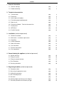
CONTENTS
1. General information
1.1 General warnings pag. 1
1.2 Product conformity pag. 3
2. Technical characteristics
2.1 Technical data pag. 4
2.2 Dimensions pag. 5
2.3 Internal parts of the boiler pag. 6
2.4 Circulation pump head/flow graph pag. 7
2.5 Water circuit pag. 8
2.6 Printed circuit board – Technical characteristics pag. 9
2.7 Control panel pag. 9
2.8 INFO Menu pag. 10
2.9 FastH2O function pag. 10
3. Installation (authorised personnel)
3.1 Reference standard pag. 11
3.2 Boiler room – installation requirements pag. 11
3.3 Unpacking pag. 12
3.4 Installing the boiler pag. 13
3.5 Water connections pag. 14
3.6 Gas connection pag. 15
3.7 Electrical connections
pag. 16
3.8 Flue connections pag. 18
4. Commissioning the appliance (authorised personnel)
4.1 General warnings pag. 25
4.2 Filling the system pag. 26
4.3 Filling the condensate trap pag. 27
4.4 Frost Protection pag. 28
4.5 Starting up the boiler pag. 30
5. Regulating the boiler (authorised personnel)
5.1 Parameters table pag. 31
5.2 Accessing the parameters menu pag. 32
5.3 Setting the parameters pag. 33
5.4 Gas valve adjustment pag. 36
5.5 Gas data pag. 42
5.6 Heating output maximum pressure diagram pag. 42
5.7 Converting the boiler to a different gas type pag. 43

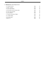
CONTENTS
6. Maintenance (authorised personnel)
6.1 General warnings pag. 44
6.2 Boiler inspection pag. 44
6.3 Accessing the boiler pag. 45
6.4 Draining the central heating system pag. 46
6.5 Flue safety thermostat pag. 46
6.6 Wiring diagrams pag. 47
6.7 Electrical connections (Option) pag. 48
6.8 Troubleshooting pag. 50
6.9 Function codes pag. 51
6.10 Parts list pag. 52

GENERAL INFORMATION
1
1. GENERAL INFORMATION
1.1 General warnings
Professionally qualified personnel in accordance with current laws and standards and in line with
the manufacturer’s instructions must install the appliance.
With ‘Professionally qualified personnel’ is intended a personnel with technical knowledge in the
field of installation and maintenance of components for central heating and domestic hot water
production systems for domestic and industrial use.
The appliance must be used solely for the purpose for which it has been designed and
manufactured: central heating and domestic hot water production. Any other use is deemed as
improper and as such dangerous. Under no circumstances will the manufacturer be held
responsible for damage or injury to persons or animals caused by errors in the installation and/or
use of the appliance, or through non-compliance with current local and national standards and/or
the manufacturer’s instructions.
The installation, operation and maintenance manual forms an integral and essential part of the
product and must be kept near the appliance always.
This manual must be kept in a safe place and made available for any future reference. If the
appliance is sold or transferred to a different owner, this must follow the appliance to be red by the
new owner and/or installer.
The warnings contained in this chapter have been written for the appliance user, the installer and
the service engineer.
The user manual must be red carefully as it provides information on the operation and the
operating limits of the appliance.
This appliance must be used exclusively in a pressurised central heating system.
• After the removal of all the packaging, check that the appliance has not been damaged. In case of doubt, do not
attempt to use the product but refer to the supplier. Packing materials (cardboard box, wooden crate, nails,
staples, plastic bags, polystyrene, etc.) must not be left within reach of children in that these items represent a
potential hazard and must be disposed of in a responsible manner.
• Before carrying out any cleaning or maintenance operations, disconnect the appliance from the mains electricity
supply by switching off at the main switch and/or any other isolating device.
• Do not obstruct the air intake or flue exhaust grills.
• Do not obstruct the air intake or flue exhaust terminals.
• In the case of a fault and/or malfunction in the appliance, shut down the system. Do not interfere with or attempt
any repairs. Call for professionally qualified technical assistance only.
• Any warranty repairs to the appliance must be carried out exclusively by the manufacturer’s authorised service
centre using original spare parts. Non-compliance with the above requirements may compromise the safety of
the appliance and invalidate the warranty. In order to guarantee the efficiency of the appliance and its correct
operation, it must be serviced regularly by professionally qualified personnel in line with the manufacturer’s
instructions.
• When the appliance is no longer required for use, any parts that may constitute potential sources of danger must
be rendered harmless.
• Only original accessories or optional extras (including electrical parts) must be used with the appliance.
• Should there be a smell of gas present in the room where the appliance is installed, DO NOT attempt to activate
any electric switches, telephones or any other equipment that may cause sparks. Open doors and windows
immediately to create a current of air and ventilate the room. Shut-off the main gas supply valve (at the meter),
or on the cylinder in the case of bottled gas, and call an authorised service centre.
• Do not attempt to interfere with the appliance in any way.

GENERAL INFORMATION
2
• As dictated by current legislation, this appliance must be installed exclusively by qualified personnel. Before
starting the boiler for the first time, make sure that it is connected to a water supply and central heating system
compatible with its performance characteristics.
• The room must be ventilated by means of an air intake positioned at floor level and protected with a grill. Make
sure the grill does not reduce the passage section.
• The air inflow from adjacent rooms is allowed providing that those rooms are in depression with respect to the
atmosphere and that there are not fireplace or fan installed. When the appliance is installed outdoor, i.e. on
balcony or terrace, make sure it is not directly exposed to atmospheric agents to prevent any damage to
components which would lead to a warranty invalidation. It is recommended to provide the boiler with a
protective casing/box against bad whether conditions.
• Check the technical data reported on the packing and on the rating plate located on the inside of the front
casing. Also check that the burner is appropriate for the type of gas to burn.
• Make sure that the pipes and fittings used for the gas service are perfectly tight and that there are no
gas leaks.
• Prior to start-up, the central heating pipes should be flushed to remove any residues that could compromise the
operation of the appliance.
• The appliance can be regarded as being electrically safe when it has been connected to an efficient earth
system installed in accordance with the requirements of current safety standards. This fundamental safety
requirement must be checked and verified. In case of doubt, have the electrical system checked by a qualified
electrician. The manufacturer will not be held liable for any damage or injury caused as a result of an ineffective
or non-existent earth system.
• The domestic power supply must be checked by a qualified electrician to ensure that it can support the
maximum power absorption of the appliance, as indicated on the appliance data plate (positioned on the inside
of the front casing). In particular, make sure that the cable ratings are adequate for the power absorbed.
• Do not use adapters; multiple sockets or extension leads to connect the appliance to the mains power supply.
• The appliance must be connected to the mains power supply through an appropriate electrical isolator in
accordance with the current wiring regulations.
• When using an electrical appliance, a few fundamental rules must be observed:
• Do not touch the appliance with damp or wet parts of the body or when barefoot
• Do not pull on the electric wires
• Do not leave the appliance exposed to atmospheric elements (rain, sun, etc,) unless these conditions have been
expressly provided for.
• Do not allow the appliance to be used by children or anyone unfamiliar with its operation.
• The user must not replace the power supply cable.
• If the cable is damaged in any way, switch off the appliance and have the cable replaced by a suitably qualified
electrician.
•
When the appliance is no longer required for use, switch off the main power supply, to switch all
electrical components off (circulating pump, burner etc.)

GENERAL INFORMATION
3
1.2 Product conformity
RADIANT BRUCIATORI S.p.A. declares that all its products are manufactured to a high specification and in
compliance with the relevant standards.
All RADIANT boilers are CE certified and possess technical and functional characteristics that comply with the
following standards:
The materials used such as copper, brass, stainless steel, etc. form a compact, homogeneous, highly functional
unit that is easy to install and simple to operate. In its simplicity, the wall-mounted appliance is equipped with all the
appropriate accessories required to make it a fully independent boiler capable of satisfying domestic hot water
production and central heating needs. All boilers are fully inspected and are accompanied by a quality certificate,
signed by the inspector, and a guarantee certificate. This manual must be kept in a safe place and must
accompany the boiler at all times.
RADIANT BRUCIATORI S.p.A. will not be held responsible for any misinterpretation of this manual resulting
from the inaccurate translation of same.
RADIANT BRUCIATORI S.p.A. will not be held responsible for the consequences in the case of non-
observance of the instructions contained in this manual or in the case where actions not specifically
described herein are undertaken.
Radiant Bruciatori S.p.A. declare that no substances harmful to health are contained in the appliance or
used during appliance manufacture and have not used or intend to use any of the following substances in
the manufacture of Radiant heating products.
−
Asbestos
−
Mercury
−
CFC's.

INSTALLATION INSTRUCTIONS
4
2. TECHNICAL CHARACTERISTICS
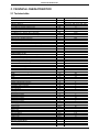
2.1 Technical data
Model
RHR 25
CE Certification n°
0694CO7385
Appliance Type II2H3+
Appliance Category C12 - C32 - C42 - C52 - C62 - C82
Heat Input max
kW 26
Heat Input min (Central Heating circuit)
kW 18
Heat Input min (Domestic Hot Water circuit)
kW 12.5
Heat Output max - 50/30°C
kW 26.44
Heat Output max - 80/60°C (Non condensing)
kW 24.93
Heat Output min - 80/60°C (Non condensing)
kW 17.23
Efficiency 100% (full load 50/30°)
% 101.7
Efficiency 30% (partial load 50/30°)
% 98.9
Efficiency 100% (full load 80/60°)
% 95.9
Efficiency 30% (partial load 80/60°)
% 94.7
GAS DIRECTIVE 92/42/ECC - Efficiency marking stars 4
NOx class 1
Flue Mass at full load g/s
15.41
Flue Mass at minimum load g/s
15.4
Flue gas temperature at full load °C
68.2
Central Heating circuit
Central Heating water temperature setting (min-max) °C 30-80 / 25-45
Max. heating working temperature °C 95
Expansion vessel capacity litres 8
Max. working pressure (heating) bar 3
Min. working pressure (heating) bar 0.3
Domestic Hot Water circuit
D.H.W. temperature setting (min-max) °C 35-75
Max. Hot water working pressure bar 6
Min. Hot water working pressure bar 0.5
D.H.W. flow rate at ∆T 30°C litr/min 12.25
Dimensions (Boiler casing size)
Width mm 450
Height mm 785
Depth mm 330
Weight (net) kg 48
Hydraulic connections
Central Heating Flow connection Ø ¾”
Central heating Return connection Ø ¾”
Cold water mains connection Ø ½”
D. Hot water connection Ø ½”
Gas connection Ø ¾”
Flue systems
Horizontal concentric Ø 60/100
Maximum flue length m 3
Horizontal twin pipe Ø 80/80
Maximum flue length m 24
Vertical concentric Ø 60/100
Maximum flue length m 3
Gas Supply
Natural gas G 20
Inlet pressure mbar 20
Gas consumption m
3
/h 2.75
Butane G30
Inlet pressure mbar 30
Gas consumption kg/h 2.05
Propane G31
Inlet pressure mbar 37
Gas consumption kg/h 2.02
Electrical specifications
Power supply V/Hz 230/50
Electrical power consumption W 145
Electrical protection IP X4D

INSTALLATION INSTRUCTIONS
5
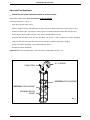
785
330
115 150 185
135
210
64.5 78 70 80 102 55.5
HFCWI
GHWO
HR
450
125
HF
CWI
G
HWO
HR
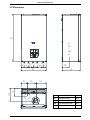
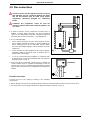
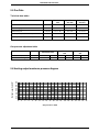
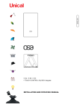
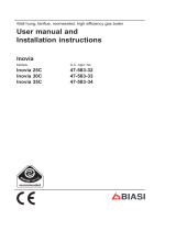
2.2 Dimensions
HR
HEATING RETURN Ø3/4”
HF
HEATING FLOW Ø3/4”
G
GAS Ø3/4”
CWI
COLD WATER INLET Ø1/2”
HWO
HOT WATER OUTLET Ø1/2”

INSTALLATION INSTRUCTIONS
6
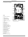
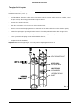
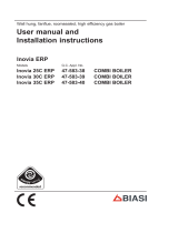
2.3 Internal parts of the boiler
LEGEND
1. FLUE SAFETY THERMOSTAT
2. FAN
3. HEAT EXCHANGER
4. COMBUSTION CHAMBER
5. IGNITION ELECTROCODE
6. BURNER
7. 3 bar PRESSURE RELIEF VALVE
8. PUMP
9. D.H.W. SENSOR
10. SISTEM DRAIN VALVE
11. FLOW LIMITER
12. ELECTRONIC GAS VALVE
13. SECONDARY HEAT EXCHANGER
14. COMBUSTION CHAMBER
15. HEATING SAFETY THERMOSTAT
16. HEATING SENSOR
17. IONISTATION ELECTROCODE
18. AIR PRESSURE SWITCH
19. CONDENSATE TRAP
20. WATER PRESSURE SWITCH
21. 3-WAY DIVERTER VALVE
22. FLOWSWITCH
23. WATER PRESSURE GAUGE
24. FILLING TAP
25. FLAT PLATE TYPE EXCHANGER

INSTALLATION INSTRUCTIONS
7
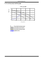
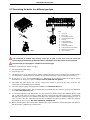
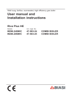
2.4 Circulation pump head/flow graph
Pump head at minimum speed
I
II
Pump head at second speed
Pump head at maximum speed
III
Appliance Loss
Flow m3/h
Head (m)
I
II III

INSTALLATION INSTRUCTIONS
8
1
2
3
4
5
6
14
7
8
10
9
11
12
13
15
16
17
18
19
20
21
22
23
24
25
26
27
28
29
30
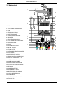
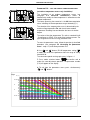
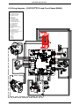
2.5 Water circuit
LEGEND
1. FLUE SAFETY THERMOSTAT
2. FAN
3. EXPANSION VESSEL
4. HEAT EXCHANGER
5. IGNITION ELECTROCODE
6. BURNER
7. ELECTRONIC GAS VALVE
8. 3 bar PRESSURE RELIEF VALVE
9. AIR VENT VALVE
10. PUMP
11. SISTEM DRAIN VALVE
12. D.H.W. SENSOR
13. FLOW LIMITER
14. SECONDARY HEAT EXCHANGER
15. FLUE HOOD
16. AIR PRESSURE SWITCH
17. ROOM SEALED CHAMBER BACK
18. SAFETY THERMOSTAT 95 °C
19. HEATING SENSOR
20. COMBUSTION CHAMBER
21. IONISTATION ELECTROCODE
22. FLAT PLATE TYPE EXCHANGER
23. BY-PASS
24. CONDENSATE TRAP
25. AUTOMATIC BY-PASS
26. WATER PRESSURE SWITCH
27. 3-WAY DIVERTER VALVE
28. FLOWSWITCH
29. WATER PRESSURE GAUGE
30. FILLING TAP

INSTALLATION INSTRUCTIONS
9
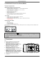
2.6 DIGITECH
®
TR Printed Circuit Board (MIAH6)
Technical characteristics
Adjustments possible by service personnel only
• Standard (30/80°C) / reduced (25-45°C) central heating temperature
• Water hammer prevention function
• Central Heating timer - (adjustable from 0 to 7,5 minutes)
• Central Heating pump overrun timer
• Minimum Gas pressure setting
• Maximum Heating Load
• Central heating maximum and minimum Set Point adjustment
• Domestic Hot Water maximum Set Point adjustment
User settings
• Heating Temperature setting (30-80°C) – (25-45°C)
• D.H.W. temperature setting (35-60°C)
• Summer only mode / Winter only mode / Summer + Winter mode selection
•
FastH2O function
Operation/Functions display
• Lock-Out
• Water law pressure
• Temperature display
• Flame presence ON (2 power steps)
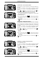
During the boiler operation the display can show 2 different power levels according to the flame modulation of the
boiler (see fig. 2).
• Error history display (last 5 errors)
To switch the boiler OFF, press INFO button, the word OFF appears on the display. The central
heating frost protection system remains enabled.
If the boiler was previously ON, it is switched OFF and the fan overrun and pump overrun functions are
enabled.
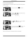
2.7 Control panel
Key
1. HEATING TEMPERATURE SETTING BUTTONS
2. INFO BUTTON: PRESS ONCE TO DISPLAY
TEMPERATURES AND INFO (see 2.8 INFO menu
display); KEEP IT PRESSED FOR 5 SECONDS (IN OFF
MODE) TO DISPLAY THE LAST 5 ERRORS.
3. MODE SELECTION BUTTON: SUMMER ONLY /
WINTER ONLY / SUMMER-WINTER / OFF.
4. RESET BUTTON: ERROR RESET – FLUE TEST
FUNCTION ACTIVATION (CHIMNEY-SWEEPER - KEEP
IT PRESSED FOR 7 SECONDS)
5. DOMESTIC HOT WATER TEMPERATURE SETTING
BUTTONS. KEEP BUTTONS ‘+’ AND ‘-‘ PRESSED FOR
5 SECONDS TO ACTIVATE THE DISPLAY BACKLIT
MODE FOR A CONTINUOUS PERIOD OF 10 MINUTES.
6. TERMINAL BLOCK FOR EXTERNAL WIRING
7. LCD DISPLAY.
1 2 3 4 5 6
7
50% 100%
Fig. 2

INSTALLATION INSTRUCTIONS
10
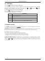
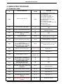
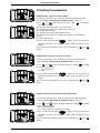
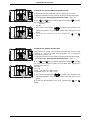
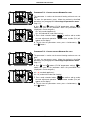
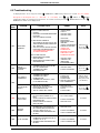
2.8 INFO Menu
Press the ‘ ’ INFO Button to display the boiler data.
Once pressed, the parameter number will appear on the left side of the display and the associated
parameter value will appear on the centre of the display. Use ‘ ’ and ‘ ’ buttons of Heating
Temperature setting to scroll the list of available data.
Press the ‘ ’ INFO button to exit the display mode.
The list of available display data is the following:
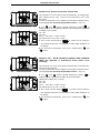
2.9 FastH2O function
The FastH2O system guarantees the immediate D.H.W supply at the requested temperature in instantaneous
boilers with secondary DH.W plate exchanger.
Functioning: the domestic heat exchanger is constantly kept at the adjusted temperature; the hot water, passing
through the pre-heated plates of the heat exchanger, reaches the water taps at the requested temperature.
The FastH2O function offers three advantages:
• the hot water is immediately supplied at the requested temperature.
• unnecessary delays are avoided by increasing the comfort of the final user.
• water wastes are limited waiting that the water reaches the right temperature.
FastH2O activation/deactivation: if the parameter 01 is set on the 01 value, i.e. instantaneous boilers secondary
DH.W plate exchanger, the“FastH2O” function can be activated/deactivated by pressing simultaneously and for 7
seconds, ‘ ’ and ‘ ’ buttons (of D.H.W temperature setting). With its activation, “Fast H2O” will be visualized
on the display.
Parameter
Description
d00
D.H.W temperature sensor
d01
Outdoor temperature sensor
d02 Kd Thermoregulation value
d03
Low temperature circuit sensor (only with Zone PCB connected)

INSTALLATION INSTRUCTIONS
11
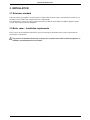
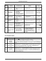
3. INSTALLATION
3.1 Reference standard
Failure to install a gas appliance correctly and in accordance with the above norms could lead to prosecution. It is in
the interest of the installer and safety that the law is complied with.
The manufacturers instructions form an integral part of the installation and should be left with the appliance but do
not over ride in anyway statutory obligations.
3.2 Boiler room – Installation requirements
Please refer to local and national standards in force in the Country of destination of the product. In particular the
manufacturer recommends:
The presence of threaded connections on the gas line, require that the room in which the appliance is
installed is ventilated by means of air intakes.

INSTALLATION INSTRUCTIONS
12
B
C
A
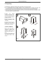
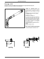
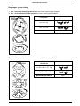
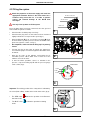
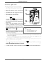
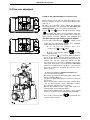
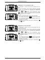
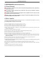
3.3 Unpacking
■
The materials (cardboard) used for packing the appliance are fully recyclable.
■ It is recommended that the packing material is only removed prior to installing the boiler. The
manufacturer will not be held responsible for damage caused by incorrect storage of the product.
■ Packing materials (plastic bags, polystyrene, nails, etc.) must not be left within reach of children, in that
these items represent a potential hazard.
A. Place the packed
appliance on the floor (see fig.
1) making sure that the "up”
arrow is facing down. Remove
the staples and open out the
four flaps of the box.
B. Rotate the boiler 90° while
manually supporting it from
underneath
C. Lift the box and remove the
protections. Lift the boiler by
grasping the rear part and
proceed with the installation.
STORAGE & HANDLING
Please note that prior to
installation the Radiant boilers
should be stored in the
horizontal position with no
more than three boilers to a
stack;
Ensure that the boilers are
stored in dry conditions and be
aware that the carton is a tow-
man lift;
Fig. 1

INSTALLATION INSTRUCTIONS
13
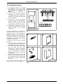
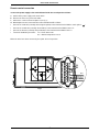
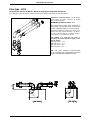
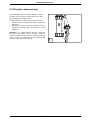
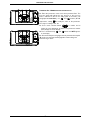
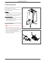
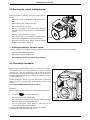
3.4 Installing the boiler
■ The appliance must be installed
exclusively on a flat vertical solid
wall capable of supporting its
weight.
■ The boiler should be fitted within the
building unless otherwise protected by
a suitable enclosure i.e. garage or
outhouse. (the boiler may be fitted
inside a cupboard.
■ If the boiler is sited in an unheated
enclosure then it is recommended to
leave the power on to give frost
protection (frost protection is active
even with on/off switch in off position).
■ If the boiler is installed in a room
containing a bath or shower reference
must be made to the relevant
requirements.
In order to allow access to the interior of
the boiler for maintenance purposes, it is
important that the necessary clearances
indicated in figure 1 are respected. To
make the installation easier, the boiler is
supplied with a template to enable the pipe
connections to be positioned prior to fixing
the appliance to the wall.
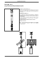
To install the boiler, proceed as follows
(see fig. 2):
a. Use a spirit level (of not less than 25
mm long) to mark a horizontal line on
the wall where the boiler is to be fitted.
b. Position the top of the template along
the line drawn with the level,
respecting the distances indicated.
Then mark the centres of the positions
of the two wall-plugs or anchors.
Finally, mark the positions of the water
and gas pipes.
c. Remove the template and install the
domestic hot and cold water pipes, the
gas supply pipe and the central heating
pipes using the fittings supplied with
the boiler.
Fix the boiler to the wall using the wall
plugs or bracket and connect the pipes.
Fig. 2
DIS TANCES [m m ]
H
A
X
L
Y
X Y L H
10006060
B
A B
200 300450
Fig. 1

INSTALLATION INSTRUCTIONS
14
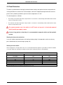
3.5 Water connections
In order to safeguard the heat exchanger and circulation pump, especially in case of boiler
replacement, it is recommended that the system is hot-flushed to remove any impurities (especially oil
and grease) from the pipes and radiators.
Make sure that the domestic water and central heating pipes are not used to earth the electrical
system. The pipes are totally unsuitable for this purpose.
Isolation Valves must be installed on the heating and D.H.W circuits. This will facilitate all maintenance
and service operations where the boiler needs to be drained.
■ To prevent vibration and noise coming from
■ the system, do not use pipes of reduced diameter, short radius elbows or severe reductions in the cross sections
of the water passages.
Domestic hot water circuit
■ In order to prevent scaling and eventual damage to the D.H.W heat exchanger, the mains water supply must not
have a hardness rating of more than 17.5 °Ck. It is nevertheless advisable to check the properties of the water
supply and install the appropriate treatment devices where necessary.
The cold water supply pressure at the inlet to the boiler must be between 0.5 and 6 bar.
In areas with higher water inlet pressure a pressure reducing valve must be fitted before the boiler.
The frequency of the heat exchanger coil cleaning depends on the hardness of the mains water supply and the
presence of residual solids or impurities, which are often present in the case of a new installation. If the
characteristics of the mains water supply are such that require it to be treated, then the appropriate treatment
devices must be installed, while in the case of residues, an in-line filter should be sufficient.
All D.H.W. circuits, connections, fittings, etc. should be fully in accordance with relevant standards and water supply
regulations.
Central heating circuit
In order to prevent scaling or deposits in the primary heat exchanger, the mains supply water to the heating circuit must be
treated according to the requirements of local standards.
This treatment is indispensable in the case where the circuit is frequently topped-up or when the system is often either partially
or fully drained.
The outlet connection of the boiler safety valve must be connected to a discharge trap. The manufacturer will not be
held responsible for flooding caused by the operation of the safety valve in the case of system overpressure.

INSTALLATION INSTRUCTIONS
15
3.6 Gas Connection
The connection to the gas supply must be carried out by professionally qualified personnel in
accordance with relevant standards:
When connecting the boiler to the gas supply pipe, only use appropriate washers and gas fittings. The
use of hemp, Teflon tape and similar materials is not allowed.
Before installing the boiler, check the following:
■ The pipe work must have a section appropriate for the flow rates requested and the pipe lengths installed, and
must be fitted with all the safety and control devices provided for by current standards.
■ The gas supply line must be a minimum of a 22 mm diameter pipe with an uninterrupted supply from meter to
boiler and comply with current standards and regulations.
■ Check the internal and external seals of the gas supply system.
■ A gas shut-off valve must be installed upstream of the appliance
■ The gas pipe work must have and bigger or equal section to the one of the boiler.
■ Before starting up the boiler, make sure that the type of gas corresponds to that for which the appliance has
been set-up (see gas type label inside the boiler).
■ The gas supply pressure must be between the values reported on the rating plate (see gas type label inside the
boiler).
■ Prior to installation, it is good practice to ensure that there are no machining residues on the gas supply pipe.
■ Conversion of the appliance from natural gas to LPG or vice versa must be carried out by qualified personnel.

INSTALLATION INSTRUCTIONS
16
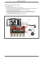
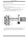
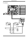
3.7 Electrical connections
General warnings
The connection to the mains power supply must be carried out by professionally qualified personnel,
registered in accordance with current legislation and authorised by Radiant Bruciatori s.p.a.
Always check to make sure that the appliance has an efficient earth system. This requirement is only
satisfied if it has been properly connected to an efficient earth system installed in accordance with the
requirements of current safety standards and carried out by professionally qualified personnel.
This basic safety measure must be checked, verified and carried out by professionally qualified personnel.
In case of doubt, have the electrical system checked by a qualified electrician. The manufacturer will not be
held liable for any damage or injury caused as a result of an inefficient or inexistent earth system;
■ The boiler functions with an alternating current of 230 V and 50 Hz and has maximum power absorption of 75
W. The appliance should be protected by a 3 A fuse. The connection to the mains electricity supply must be
via a single-pole switch, with at least 3 millimetres gap between open contacts, mounted upstream of the
appliance. Make sure that the positions of the live and neutral wires correspond to the wiring diagram;
■ Ensure the domestic power supply is checked by a qualified electrician to ensure that it can support the
maximum power absorption of the appliance, as indicated on the rating plate. In particular, make sure that the
cable sizes are adequate for the power absorbed by the appliance;
■ The power supply cable must not be replaced by the user. if the cable is damaged in any way, switch off the
appliance and have the cable replaced by a suitably qualified electrician;
■ The power supply cable must be at least of section 1mm
2
;
When using an electrical appliance, a few fundamental rules must be observed:
• Do not touch the appliance with damp or wet parts of the body or when barefoot.
• Do not pull on the electric wires.
• Do not leave the appliance exposed to atmospheric elements (rain, sun, etc,) unless these conditions have
been expressly provided for.
• Do not allow the appliance to be used by children or anyone unfamiliar with its operation;
Page is loading ...
Page is loading ...
Page is loading ...
Page is loading ...
Page is loading ...
Page is loading ...
Page is loading ...
Page is loading ...
Page is loading ...
Page is loading ...
Page is loading ...
Page is loading ...
Page is loading ...
Page is loading ...
Page is loading ...
Page is loading ...
Page is loading ...
Page is loading ...
Page is loading ...
Page is loading ...
Page is loading ...
Page is loading ...
Page is loading ...
Page is loading ...
Page is loading ...
Page is loading ...
Page is loading ...
Page is loading ...
Page is loading ...
Page is loading ...
Page is loading ...
Page is loading ...
Page is loading ...
Page is loading ...
Page is loading ...
Page is loading ...
Page is loading ...
Page is loading ...
-
 1
1
-
 2
2
-
 3
3
-
 4
4
-
 5
5
-
 6
6
-
 7
7
-
 8
8
-
 9
9
-
 10
10
-
 11
11
-
 12
12
-
 13
13
-
 14
14
-
 15
15
-
 16
16
-
 17
17
-
 18
18
-
 19
19
-
 20
20
-
 21
21
-
 22
22
-
 23
23
-
 24
24
-
 25
25
-
 26
26
-
 27
27
-
 28
28
-
 29
29
-
 30
30
-
 31
31
-
 32
32
-
 33
33
-
 34
34
-
 35
35
-
 36
36
-
 37
37
-
 38
38
-
 39
39
-
 40
40
-
 41
41
-
 42
42
-
 43
43
-
 44
44
-
 45
45
-
 46
46
-
 47
47
-
 48
48
-
 49
49
-
 50
50
-
 51
51
-
 52
52
-
 53
53
-
 54
54
-
 55
55
-
 56
56
-
 57
57
-
 58
58


Ask a question and I''ll find the answer in the document
Finding information in a document is now easier with AI
Related papers
-
Radiant RBS 24 User manual
-
-
Radiant RKA 20 User manual
-
-
-
-
-
-
-
Other documents
-
DREO DR-HSH001 User guide
-
 Biasi Riva Plus HE Combi ERP 24kw and 28kw User manual
-
 Unical OSA S Installation guide
-
Sime Dewy 90A 110A Owner's manual
-
 Biasi Riva Plus HE M296.24SM/C, M296.28SM/C User manual
-
 Biasi Inovia Combi ERP User manual
-
-
 Biasi Inovia 35C User manual
-
-
Biasi Activ A 30C User manual


