Page is loading ...

OWNER’S MANUAL
& OPERATING INSTRUCTIONS
12039 Smith Ave.
Santa Fe Springs CA 90670 USA
1-877-338-0999
www.championpowerequipment.com
GARDEN SINK
SAVE THESE INSTRUCTIONS
Important safety instructions
are included in this manual.
MADE IN CHINA
REV 50075-20140319
50075
MODEL NUMBER

*We are always working to improve our products. Therefore, the enclosed product may differ slightly from the image on the cover.
Have questions or need assistance?
Do not return this product to the store!
WE ARE HERE TO HELP!
Visit our website:
www.championpowerequipment.com
for more info:
• Product Info and Updates
• Frequently Asked Questions
• Tech Bulletins
• Product Registration
– or –
Call our Customer Care Team Toll-Free at:
1-877-338-0999

50075
GARDEN SINK
TABLE OF CONTENTS
Manual conventions ....................... 1
Introduction ............................ 2
Before you begin ....................... 2
Parts ................................ 3
Parts included ........................ 3
Tools required (not included) .............. 3
Replacement parts ..................... 3
Assembly .............................. 4
Wood mounting ........................ 4
Masonry or brick mounting ................ 4
Installing the hose hanger ................ 5
Installing the sink ...................... 5
Connecting the hoses. . . . . . . . . . . . . . . . . . . . 6
Operation .............................. 7
Water flow ........................... 7
Storage ............................... 8
Storing the sink ........................ 8
Specifications ........................... 9
Parts diagram ......................... 9
Parts list ........................... 10
Warranty ............................. 11
Warranty qualifications .................. 11
Repair/replacement warranty .............. 11
Do not return the unit to
the place of purchase .................. 11
Warranty exclusions .................... 11
Normal wear ....................... 11
Installation, use and maintenance ........ 11
Other exclusions .................... 11
Limits of implied warranty
and consequential damage ............. 11
Contact information .................... 11
Address .......................... 11
Customer service ................... 11
Technical service ................... 11

1 REV 50075-20140319
ENGLISH 50075
This manual uses the following symbols to help differentiate between different kinds of information. The safety symbol
is used with a key word to alert you to potential hazards in operating and owning power equipment.
Follow all safety messages to avoid or reduce the risk of serious injury or death.
MANUAL CONVENTIONS
CAUTION indicates a potentially hazardous
situation which, if not avoided, may result in minor
or moderate injury.
CAUTION
WARNING indicates a potentially hazardous
situation which, if not avoided, could result in
death or serious injury.
WARNING
If you have questions regarding your garden sink, we
can help. Please call our help line at 1-877-338-0999
NOTE

REV 50075-20140319 2
50075 ENGLISH
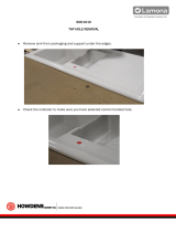
Before you begin
This product has been packaged to ensure it arrives in best possible condition. Please be careful
when unpacking. Read instructions prior to assembly. This kit contains parts that can be damaged if
incorrectly assembled. Please follow instructions. Champion Power Equipment is not responsible for
replacing parts damaged due to incorrect assembly.
Record the model and serial numbers as well as date and place of purchase for future reference. Have this
information available when ordering parts and when making technical or warranty inquiries.
Champion Power Equipment Support
Model Number
Serial Number
Date of Purchase
Purchase Location
1-877-338-0999
50075
INTRODUCTION
DO NOT dump solids, cleaners or chemicals down
the sink drain.
DO NOT drink the water from the sink.
CAUTION
Please consider carefully the appropriate method
to be used in mounting this garden sink. Hardware
is included for your convenience, but may not be
suitable for all mounting conditions. Some surfaces
like vinyl siding or stucco may require special
considerations or additional hardware. Improper
mounting can cause personal injury or property
damage. If you are unsure, contact a home
improvement professional.
CAUTION
DO NOT lean, sit, stand, jump or place heavy
objects on the garden sink. The garden sink
mounting is not designed to bare heavy weight.
WARNING
Do not completely tighten bolts until assembly is
completed. For easier assembly, we recommend that
two people assemble this product.
NOTE

3 REV 50075-20140319
ENGLISH 50075
Tools required (not included)
– Powered hand drill or hammer drill
– 4 mm (5/32 in.) wood drill bit
– 6 mm (15/64 in.) masonry drill bit
– Screwdriver tip bit
– Small hammer or mallet
– Phillips screwdriver (small and medium)
– 8 mm wrench
– Crescent wrench (adjustable wrench)
– Pencil or marker
PARTS
Parts included
– Garden sink ........................... 1
– Support frame ......................... 1
– Storage drawer (2 separate pieces) ........... 1
– Hose hanger ........................... 1
– Drain catch ........................... 1
– M3x10 self tapping screw .................. 3
– M5x35 bolt ........................... 2
– M5 nut .............................. 2
– Expansion sleeve ........................4
– M6x60 bolt (for wood) .................... 4
#19
#32
#33
#3
#30
#17
#15/#16
#35
#29
#18
Replacement parts
For replacement parts, contact:
Address
Champion Power Equipment, Inc.
Customer Service
12039 Smith Ave.
Santa Fe Springs, CA 90670
www.championpowerequipment.com
Customer Service
Mon – Fri 8:30 AM – 5:00 PM (PST/PDT)
Toll Free: 1-877-338-0999
Fax no.: 1-562-236-9429
Technical Service
Mon – Fri 8:30 AM – 5:00 PM (PST/PDT)
Toll Free: 1-877-338-0999
tech@championpowerequipment.com
Other components may be identified by part
numbers marked on the part.
Anchors for masonry application only.
NOTE

REV 50075-20140319 4
50075 ENGLISH
Side view
Wall
Anchor
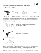
Wood mounting
Tools required (not included):
– Powered hand drill or hammer drill
– 4 mm (5/32 in.) wood drill bit
– Screwdriver tip bit
– Pencil or marker
Instructions:
1. Using a pencil or marker, locate and mark 4 studs
on the wall.
2. Using the mounting template provided, try and aline
the holes in the template with the marks for studs.
3. Mark the 4 needed hole spots for mounting,
indicated on the mounting template.
4. Using the 4 mm (5/32 in.) wood drill bit, drill pilot
holes into the 4 marked hole spots.
5. Have an assistant hold the sink frame (#32) up
against the wall, aligning the 4 holes in the frame
with the 4 pilot holes on the wall.
Masonry or brick mounting
Tools required (not included):
– Powered hand drill or hammer drill
– 6 mm (15/64 in.) masonry drill bit
– Screwdriver tip bit
– Hammer or mallet
– Pencil or marker
Instructions:
1. Using a pencil or marker and the mounting template
provided, mark 4 spot holes on the wall.
2. Using the 6 mm (15/64 in.) masonry drill bit, drill
pilot holes into the 4 marked hole spots.
3. Insert a wall anchor into the pilot hole as far as you
can with your hand.
ASSEMBLY
Carefully remove all parts from the packing box.
Locate all hardware and components before
installation.
NOTE
If studs can not be found or aligned properly with
the template and frame, the supplied wall anchors
should be used to help secure frame to wall.
NOTE
Mounting on other materials than wood, masonry or
brick, may require other hardware.
NOTE
6. Using a power hand drill or hammer drill with a
screwdriver tip bit, secure a M6x60 wood screw
(#17) into a pilot hole on the wall, through the hole
in the sink frame.
7. Repeat for the 3 remaining holes.
8. Tighten all screws but do not overtighten.
9. Make sure the support frame is secure on the wall
before continuing.
To prevent damage or injury, be sure to verify that
holes align with stud locations in the wall.
CAUTION
To prevent injury, always wear proper safety goggles
and safety gear when assembling or installing the
garden sink.
CAUTION
Wood mounting cont’d.
4. Using the hammer or mallet, gently tap the wall
anchor (#18) firmly into the pilot hole.
5. Repeat for the remaining 3 holes.
6. Have an assistant hold the sink frame (#32) up
against the wall, aligning the 4 holes in the frame
with the 4 holes in the anchors on the wall.

5 REV 50075-20140319
ENGLISH 50075
4. Line up the 2 holes in the drain hose connector (#24)
with the two holes on the bottom of the frame. These
holes will be on the right side of the frame. (C)
5. Thread the M5x35 bolts (#29) through the drain
hose connector and frame. (C)
6. Using the crescent (adjustable) or a 8 mm wrench
and medium phillip head screwdriver, secure the
hose connector to the frame by tightening the M5
nuts (#30) onto the M5x35 bolts. (C)
ASSEMBLY
7. Using a power hand drill or hammer drill with a
screwdriver tip bit, secure a M6x60 wood screw
(#17) into a pilot hole on the wall, through the hole
in the sink frame.
8. Repeat for the 3 remaining holes.
9. Tighten all screws but do not overtighten.
10. Make sure the support frame is secure on the wall
before continuing.
Masonry or brick mounting cont’d. Installing the sink cont’d.
Installing the hose hanger
1. Align the prongs of the hose hanger with the 2 holes
on the bottom frame cross bar.
2. Insert the prongs into the holes. No nuts are needed
to hold in place.
Installing the sink
Tools required (not included):
– Phillips screwdriver (small and medium)
– 8 mm and crescent (adjustable) wrench
Instructions:
1. Using the medium or small phillip head screwdriver,
attach the drain outlet connector (#21) to the drain
hole on the bottom of the sink with the 3 M3x10 self
tapping screws (#3). (A)
The hose hanger is designed to be easily assembled
or disassembled quickly.
NOTE
A
B
C
D
C
D
2. Tighten all screws. Do not overtighten.
3. Install the sink (#19) over the top of the frame
(#32). (B)
7. Tighten both nuts. Do not overtighten.
8. Take the storage drawer (#15, #16) and insert the
left end first, and then the right end until a snap is
heard. (D)
9. The right end has a latch that should catch. (D)
10. Lift the cover and fold it back into the left side of
the frame, until it sits in the groove of the sink on
the left side. (E)

REV 50075-20140319 6
50075 ENGLISH
ASSEMBLY
Installing the sink cont’d.
Connecting the hoses
1. Insert the male end of a garden hose or other water
supply hose to the female end of the water supply
outlet in the hose conncetor. (1)
2. Turn the knob on the female end of the hose
connector until tight. Do not overtighten.
3. Connect the female end of a drainage hose to the
drain outlet in the hose connector. (2)
4. Tighten until the drainage hose is secure. Do not
overtighten.
5. Once the hoses have been connected the water
supply can be turned on. The water will not flow
through the faucet until the top lever is flipped.
Turn the water supply off when the sink is not in
use.
NOTE
2
1
2
1
E
F
E
F
11. Once the cover has been converted to the table top,
the collaspible faucet can be turned up and locked
into place. (E)
The convertible cover/table top must be secured in
the groove on the side of the sink before any light
material is placed atop of it. It is not recommended
that any heavy material be placed on it. Heavy
material may collapse the cover/top and may cause
damage or injury.
CAUTION
Ensure the drainage hose does not lead to anything
that it may soak or cause water or other damage to.
CAUTION
12. Place the drain catch (#35), prong side up, on top
of the drain in the sink. Make sure it is secure by
pressing down on it. (F)

7 REV 50075-20140319
ENGLISH 50075
OPERATION
Water flow
1. Once the proper have been connected, and the water
supply turned on, the switch on the faucet head can
be flipped to the “ON” position. (A)
2. Flipping the faucet head switch “ON” or “OFF” will
allow the water supply to flow through the faucet
from the water supply hose.
Water will only flow through the faucet when the
supply is turned on and the faucet head switch
flipped to the “ON” position.
NOTE
A

REV 50075-20140319 8
50075 ENGLISH
STORAGE
It is recommended that the sink be covered during
storage as moisture or rain may cause the metal
parts to rust.
NOTE
A
B
Storing the sink
1. Turn the faucet head switch to the “OFF” position.
2. Turn the water supply off.
3. Allow any excess water to drain. This may take a
minute or two.
4. Disconnect the water hose from the hose connector.
5. Disconnect the drainage hose from the hose
connector.
6. Depressing the tongue of the faucet will collapse it
back into the sink tub. (A)
Make sure the hoses have been disconnected and
no liquid in the tubes. Residual liquids may freeze
in colder weather, causing expansion and possible
damage.
CAUTION
7. Once the faucet has been collapsed into the sink tub
the table top can be converted back into the sink
cover and flipped over the sink tub. (B)

9 REV 50075-20140319
ENGLISH 50075
SPECIFICATIONS
Parts Diagram

REV 50075-20140319 10
50075 ENGLISH
SPECIFICATIONS
# Part Number Description Qty
1 50075-01 Tap - Top Cover 1
2 50075-02 Tap - Switch 1
3 50075-03 M3x10 Self-tapping Screw 11
4 50075-04 Tap - Switch Base 1
5 50075-05 Tap - Switch Swivel Axle 1
6 50075-06 Outlet Cover 1
7 50075-07 Clip 4
8 50075-08 Seal Ring A ID17 x WD2 2
9 50075-09 Seal Ring B ID5 x WD2 1
10 50075-10 Pressing Block A 1
11 50075 -11 Tap - Cover 2
12 50075-12 Pressing Block B 1
13 50075 -13 Connecting Sink Cover 1
14 50075-14 Sink Cover 1
15 50075 -15 Drawer Cover 2
16 50075 -16 Drawer Cover Frame 2
17
50075-17 M6x60 Wood Screw
4
18 50075 -18 Expansion Pipe 4
19 50 075-19 Sink 1
# Part Number Description Qty
20 50075-20 Seal Ring C ID21 x WD2 1
21 50075-21 Outlet Connector 1
22 50075-22 Hose A 1
23 50075-23 Hose B 1
24 50075-24 Hose Connector part 1
25 50075-25 Drain Fittiing 1
26 50075-26 Inlet Fitting 1
27 50075-27 Washer 1
28 50075-28 3/4 in. Plastic Nut 1
29 50075-29 M5 x 35 Screw 1
30 50075-30 M5 Nut 1
31 50075-31 M4 x 16 Self-tapping Screw 4
32 50075-32 Support Frame 1
33 50075-33 Hanger 1
34 50075-34 Seal Ring 1
35 50075-35 Drain catch 1
36 50075-36 O Ring ID12 x WD2.62 1
37 50075-37 Sink Tub 1

11 REV 50075-20140319
ENGLISH 50075
WARRANTY
CHAMPION POWER EQUIPMENT
2-YEAR LIMITED WARRANTY
Warranty qualifications
Champion Power Equipment (CPE) will register this
warranty upon receipt of your Warranty Registration Card
and a copy of your sales receipt from one of CPE’s retail
locations as proof of purchase.
Please submit your warranty registration and your proof
of purchase within ten (10) days of the date of purchase.
Limited repair/replacement warranty
CPE warrants to the original purchaser that the
components will be free of defects in material and
workmanship for a period of two (2) years from the
original date of purchase.
Transportation charges on product submitted for
repair or replacement under this warranty are the sole
responsibility of the purchaser. This warranty applies
only to the original purchaser and is not transferable.
Do not return the unit to the place of purchase
Contact CPE’s Technical Service and CPE will
troubleshoot any issue via phone or e-mail. If the
problem is not corrected by this method, CPE will, at its
option, authorize evaluation, repair or replacement of the
defective part or component at a CPE Service Centre.
CPE will provide you with a case number for warranty
service. Please keep it for future reference. Repairs
or replacements without prior authorization, or at an
unauthorized repair facility, will not be covered by this
warranty.
Warranty exclusions
This warranty does not cover the following repairs and
equipment:
Normal wear
This warranty does not cover repair when normal use has
exhausted the life of a part or the equipment as a whole.
Installation, use and maintenance
This warranty will not apply to parts and/or labour if this
garden sink is deemed to have been misused, neglected,
involved in an accident, abused, modified, installed
improperly or connected incorrectly to any hose kit.
Other exclusions
This warranty excludes:
– Cosmetic defects such as paint, decals, etc.
– Failures due to acts of God and other force majeure
events beyond the manufacturer’s control.
– Problems cause by parts that are not original
Champion Power Equipment parts.
Limits of implied warranty and consequential damage
Champion Power Equipment disclaims any obligation to
cover any loss of time, use of this product, freight, or
any incidental or consequential claim by anyone from
using this garden sink.
THIS WARRANTY IS IN LIEU OF ALL OTHER
WARRANTIES, EXPRESS OR IMPLIED, INCLUDING
WARRANTIES OF MERCHANTABILITY OR FITNESS
FOR A PARTICULAR PURPOSE.
A unit provided as an exchange will be subject to the
warranty of the original unit. The length of the warranty
governing the exchanged unit will remain calculated by
reference to the purchase date of the original unit. This
warranty gives you certain legal rights which may change
from province to province. Your state may also have
other rights you may be entitled to that are not listed
within this warranty.
Contact information
Address
Champion Power Equipment, Inc.
Customer Service
12039 Smith Ave.
Santa Fe Springs, CA 90670 USA
www.championpowerequipment.com
Customer service
Mon – Fri 8:30 AM – 5:00 PM (PST/PDT)
Toll Free: 1-877-338-0999
info@championpowerequipment.com
Fax no.: 1-562-236-9429
Technical service
Mon – Fri 8:30 AM – 5:00 PM (PST/PDT)
Toll Free: 1-877-338-0999
tech@championpowerequipment.com
WARRANTY
/