Page is loading ...

LT-6613 Rev 1 Page 1 of 9
RB-MD-1236 Replacement Audio Mixer Board
TX3-TOUCH-S15-B and TX3-TOUCH-F15-B: this page
TX3-TOUCH-S22 and TX3-TOUCH-F22: page 5
TX3-TOUCH-S15-B, TX3-TOUCH-F15-B, TX3-TOUCH-S22-C, TX3-TOUCH-F22-C: page 9
TX3-TOUCH-S15-B and
TX3-TOUCH-F15-B
These instructions explain how to replace MD-1105 with the RB-MD-1236 Replacement
Audio Mixer Board in TX3-TOUCH-S15-B and TX3-TOUCH-F15-B.
A. Shut down the Touch Screen
1. At the Touch Screen terminal, enter 9999.
2. Enter your administrator password, and then press OK.
3. Select File > Shut down > Shut down.
4. After the TX3 Configurator and Windows have shut down, disconnect power from the
Touch Screen.
5. Turn off the lobby controller board.
B. Remove the old board
Caution: To prevent damage to the boards, always hold them by the edges.
1. Disconnect all wires from the current mixer board.
2. Unscrew the four screws that hold the current mixer board in place, and remove the
current mixer board.
C. Attach the new board
1. Secure the new board with the four screws you removed in step B.
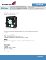
Figure 1 Location of circuit boards on the Touch Screen chassis
PC board
Telephone
access
controller
board
Audio mixer
board

LT-6613 Rev 1 Page 2 of 9
2. Move the SW3 switch to the left.
Figure 2 SW3 on the left
3. Connect the cables to the new board. Refer to the figures below.
4. Turn on the lobby controller board.
5. Turn on the Touch Screen.
You are done! If you need more help, call us at 1-888-660-4655.
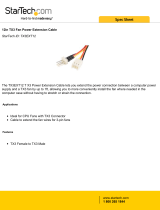
Note: Use the existing cables for the power connections to TS9 and for the button
connections (SW-207), and use the cables included with this kit for all other
connections.
Figure 3 Connections on MD-1236 for TX3-TOUCH-S15-B and TX3-TOUCH-F15-B
WX-081: CN1 on PC board
WX-079: CN31 on PC board
WX-109: TS2 on telephone
access controller (not
polarity sensitive)
WR-21160 and WR-21162:
Power (CN6)
on PC board
+
-
WX-110: TS4 (bottom)
on telephone access
controller
WR-12223 and WR-12224:
Left Speaker
WR-12223 and WR-12224:
Right Speaker
WX-080: CN2
on PC board
P3
P1
TS1
TS4A
TS12
P2
TS9
SW-207: Button
WR-21160 and
WR-21162: Power
terminals
TS11
SW3 on the LEFT
TS10A
TS4B
TS7
WX-520: CN4
on PC board
only if fan is
present
TS6A
Fan (if present)
+
-
WX-070:
Ground wire to
chassis ground
WX-070: Ground
wire to telephone
access controller
-
+
+
-
-
+
Black (ground)
White (data)
Red (clock)
Yellow
Blue
Red
Red Black
Red Black
Red
Black
Yellow
Orange
Yellow
Orange
Red
Black
Red
Black
White
Green

LT-6613 Rev 1 Page 3 of 9
Figure 4 Wiring the button
Figure 5 Connections from the telephone access controller board to MD-1236 on TX3-
TOUCH-S15-B and TX3-TOUCH-F15-B
4
TS11 on
MD-1236
321
Button (bottom view)
Notch
Notch
Button (side view)
black (-)
white
red (+)
green
black (-)
2
green
4
red (+)
1
white
3
WX-110: TS1 on
MD-1236
TS4
WX-109: TS12 on
MD-1236
(not polarity sensitive)
TS2
TS2
Power switch
+
-
WX-070:
Ground wire
to MD-1236
Black
Red
Black
Red

LT-6613 Rev 1 Page 4 of 9
Figure 6 Connections from the PC sub compact board to MD-1236 for TX3-TOUCH-
S15-B and TX3-TOUCH-F15-B
CN6
CN2
WX-081: P3 on
MD-1236
CN1
WX-079: P1 on
MD-1236
CN31
CN4
WX-080: P2 on
MD-1236
WR-21160 and
WR-21162: TS10A on
MD-1236
+
-
WX-520: TS7 on
MD-1236 only if
fan is present
NOTE: Use only
the top 3 pins
Black (ground)
White (data)
Red (clock)
Red
Black

LT-6613 Rev 1 Page 5 of 9
TX3-TOUCH-S22 and TX3-TOUCH-
F22
These instructions explain how to replace MD-1105 with the RB-MD-1236 Replacement
Audio Mixer Board in TX3 Touch 22 inch models.
A. Shut down the Touch Screen
1. At the Touch Screen terminal, enter 9999.
2. Enter your administrator password, and then press OK.
3. Select File > Shut down > Shut down.
4. After the TX3 Configurator and Windows have shut down, disconnect power from the
Touch Screen.
5. Turn off the lobby controller board.
B. Remove the old board
Caution: To prevent damage to the boards, always hold them by the edges.
1. Disconnect all wires from the current mixer board.
2. Unscrew the four screws that hold the current mixer board in place, and remove the
current mixer board.
C. Attach the new board
1. Secure the new board with the four screws you removed in step B.
Figure 7 Location of circuit boards on the Touch Screen chassis
2. Move the SW3 switch to the left.
PC board
Telephone
access
controller
board
Audio mixer
board

LT-6613 Rev 1 Page 6 of 9
Figure 8 SW3 on the left
3. Connect the cables to the new board. Refer to the figures below.
4. Turn on the lobby controller board.
5. Turn on the Touch Screen.
You are done! If you need more help, call us at 1-888-660-4655.
Note: Use the existing cables for the power connections to TS9 and for the button
connections (SW-207), and use the cables included with this kit for all other
connections.
Figure 9 Connections on audio mixer board for TX3-TOUCH-S22 and TX3-TOUCH-F22
Figure 10 Wiring the button
P3
P1
TS1
TS4A
TS12
P2
TS9
SW3 on the LEFT
SW3
TS4B
MD-1268: Power on
22 inch display
+
-
TS10B
TS10A
TS7
TS11
TS6A
WX-079: CN31 on PC board
WX-520: CN4
on PC board
only if fan is
present
Black (ground)
White (data)
Red (clock)
Fan (if present)
WX-081: CN1 on PC board
WX-070:
Ground wire to
chassis ground
WX-070: Ground
wire to telephone
access controller
WX-080: CN2
on PC board
Yellow
Blue
Red
SW-207: Button
Red
Black
White
Green
WR-21160 and
WR-21162: Power
terminals
+
-
Red Black
WX-109: TS2 on telephone
access controller (not
polarity sensitive)
Red Black
WX-110: TS4 (bottom)
on telephone access
controller
WR-12223 and WR-12224:
Left Speaker
WR-12223 and WR-12224:
Right Speaker
+
-
-
+
-
+
Yellow
Orange
Yellow
Orange
Red
Black
WR-21160 and WR-21162:
Power (CN6)
on PC board
+
-
Red
Black
Red
Black
4
TS11 on
MD-1236
321
Button (bottom view)
Notch
Notch
Button (side view)
black (-)
white
red (+)
green
black (-)
2
green
4
red (+)
1
white
3

LT-6613 Rev 1 Page 7 of 9
Figure 11 Connections from the telephone access controller board to MD-1236 on TX3-
TOUCH-S22 and TX3-TOUCH-F22
Figure 12 Connections from the PC sub compact board to MD-1236 on TX3-TOUCH-
S22 and TX3-TOUCH-F22
WX-110: TS1 on
MD-1236
TS4
WX-109: TS12 on
MD-1236
(not polarity sensitive)
TS2
TS2
Power switch
+
-
WX-070:
Ground wire
to MD-1236
Black
Red
Black
Red
CN6
CN2
CN1
CN31
CN32
Touch Screen VGA
cable
CN14
CN4
WX-080: P2 on
MD-1236
WX-081: P3 on
MD-1236
WX-082:
USB to display
WX-079: P1 on
MD-1236
WR-21160 and
WR-21162: TS10A on
MD-1236
+
-
WX-520: TS7 on
MD-1236 only if
fan is present
NOTE: Use only
the top 3 pins
Black (ground)
White (data)
Red (clock)
Red
Black

LT-6613 Rev 1 Page 8 of 9
Figure 13 Connections on the 22 inch display
WX-082: USB
extension on PC
sub compact
board
CN32 on PC sub
compact board
MD-1256: TS10B on
MD-1236

LT-6613 Rev 1 Page 9 of 9
TX3-TOUCH-S15-C,
TX3-TOUCH-F15-C,
TX3-TOUCH-S22-C,
TX3-TOUCH-F22-C
These instructions explain how to replace MD-1236 with the RB-MD-1236 Replacement
Audio Mixer Board in TX3-TOUCH-S15-C, TX3-TOUCH-F15-C, TX3-TOUCH-S22-C, and
TX3-TOUCH-F22-C.
A. Shut down the Touch Screen
1. At the Touch Screen terminal, enter 9999.
2. Enter your administrator password, and then press OK.
3. Select File > Shut down > Shut down.
4. After the TX3 Configurator and Windows have shut down, disconnect power from the
Touch Screen.
5. Turn off the lobby controller board.
B. Remove the old board
Caution: To prevent damage to the boards, always hold them by the edges.
1. Disconnect the power harness from the current audio mixer board.
2. Disconnect the ribbon cable from the current audio mixer board, if it is present.
3. Disconnect all input, output, and networking harnesses from the current audio mixer
board.
4. Unscrew the four #8-32 screws that hold the current board in place.
C. Attach the new board
1. Secure the new board with the four screws you removed in step B.
2. Connect all the input, output, and networking harnesses to the new board.
3. Connect the power harness to the new board.
4. Turn on the lobby controller board.
5. Turn on the Touch Screen.
You are done! If you need more help, call us at 1-888-660-4655.
/