Page is loading ...

© ITW Finishing Systems & Products 2009 Page 1
83C-210-CE & 83Z-210-CE PRESSURE TANK
Small Tank - Up To 9.5 litres (2.8 US Gallons)
IMPORTANT: Read and follow all instructions and SAFETY PRECAUTIONS before using
this equipment. Retain for future reference.
SB-E-21-041
DESCRIPTION
These Pressure Tanks are CE
marked in accordance with the
Pressure Equipment Directive
97/23/EC and ATEX Directive 94/9/
EC Cat 2 G X for use in Zones 1
and 2. They are suitable for use
with flammable and waterbased
(83Z only) materials.
These pressure tanks are designed as a
pressure container to supply liquid material at
a constant preset pressure up to a maximum
of 5.5 bar (80 psi). The tanks are built to
ASME specifications. 83C models are
constructed from electro-zinc plated carbon
steel. 83Z models have stainless steel fluid
passages and lid A polyethylene liner is
included for easy clean up.
Models:
83C-210: Single regulation, electro-zinc
plated carbon steel construction lid and shell.
83Z-210: Single regulation, electro-zinc
plated carbon steel shell, stainless steel fluid
passages and lids for waterbased materials.
Halogenated hydrocarbon solvents - for
example: 1,1,1, - trichloroethane and
methylene chloride - can chemically react with
aluminium parts and components and cause
an explosion hazard. These solvents will also
corrode the galvanized tank coating. Read the
label or data sheet for the material. Do not
use materials containing these solvents
with these pressure tanks.
Refer to specifications chart to ensure that
fluids and solvents being used are chemically
compatible with the tank wetted parts. Before
placing fluids or solvents in tank, always read
accompanying manufacturer's literature and
MSDS.
Air pressure loads that are higher than
design loads, or changes to the pressure feed
tank can cause the tank to rupture or explode.
· A safety valve protects the tank from over
pressurization. During each use pull the ring
on the safety valve to make sure it operates
freely and relieves air pressure. If the valve is
stuck, does not operate freely, or does not
relieve air pressure, it must be replaced. Do
not eliminate, make adjustments or
substitutions to this valve.
· Changes to the air tank will weaken it. Never
drill into, weld or change the tank in any way.
· The maximum working pressure of this tank
is 5.5 bar (80 psi).
Static electricity can be created by the flow
of fluid through the pressure tank and hose. If
all parts are not properly grounded, sparking
may occur. Sparks can ignite vapours from
solvents and the fluid being sprayed.
Ground the pressure tank by using conductive
air hoses and/or use of an ATEX approved
grounding clamp from the tank and the other
end to a true earth ground.
If static sparking, or slight shock, is
experienced while using this equipment, stop
spraying immediately. Check continuity to
earth before continuing to use the equipment.
Pressure Relief Procedure
High pressure can cause a serious injury.
Pressure is maintained in a pressure tank
after the system has been shut down. Before
attempting removal of the cover, pressure
must be relieved using the following steps:
1. Turn off the main air supply to the tank.
2. Close air inlet valve located on tank air
manifold.
3. Bleed off air in the tank by turning the air
relief valve thumb screw counterclockwise.
Wait until all the air has escaped through the
valve before removing the pressure tank
cover.
4. Leave the air relief valve open until you
have reinstalled the cover.
ISS.04
SB-E-21-041-R1 (2/2018) 1 / 6 www.carlisleft.com
EN

© ITW Finishing Systems & Products 2009 Page 2
SAFETY PRECAUTIONS
This manual contains information that is important for you to know and understand. This information relates to USER SAFETY and
PREVENTING EQUIPMENT PROBLEMS. To help you recognize this information, we use the following symbols. Please pay
particular attention to these sections
Important information that tells how to
prevent damage to equipment, or how to
avoid a situation that may cause minor
injury.
Important safety information - A hazard
that may cause serious injury or loss of
life.
NOTE
Information that you should pay special
attention to.
The following hazards may occur during the normal use of this equipment. Please read the following chart.
HAZARD CAUSE SAFEGUARDS
FIRE
Solvents and coatings can be highly
combustible, especially when sprayed.
1. Adequate exhaust must be provided
to keep the air free of accumulations
of flammable vapours
2. Smoking must never be allowed in
the spray area.
3. Fire extinguishing equipment must be
present in the spray area.
FIRE - PRESSURE TANK
Vapours from flammable liquids can catch
fire or explode
1. Keep tank at least 3 metres away
from sources of ignition, including hot
surfaces, mechanical sparks and
arcing (non-explosion proof) electrical
equipment.
INHALING TOXIC
SUBSTANCES
Certain materials may be harmful if
inhaled, or there is contact with the skin.
1. Follow the requirements of the
Material Safety Data Sheet supplier
by the coating manufacturer.
2. Adequate exhaust must be provided
to keep the air free of accumulations
of toxic materials.
3. Use a mask or respirator wherever
there is a risk of inhaling sprayed
materials. The mask must be suitable
for the material being sprayed.
EXPLOSION, PRESSURE
TANK—RUPTURE
Making any changes or modification to
the pressure tank may weaken it.
1. Never drill into, weld or modify the
tank in any way.
2. Do not adjust, remove or tamper with
the safety valve.
3. Only replace the safety valve with the
correct spare part as listed.
4. Do not fit any other safety valve of a
higher pressure rating than the
maximum working pressure of the
tank.
GENERAL SAFETY
Improper operation or maintenance may
create a hazard.
Operators should be given adequate
training in the safe use and maintenance
of this equipment. Refer to Pressure
Systems Safety Regulations 2000
Approved Code of Practice
EN
SB-E-21-041-R1 (2/2018)2 / 6www.carlisleft.com

© ITW Finishing Systems & Products 2009 Page 3
INSTALLATION
Mix and prepare material to be used
according to manufacturer's instructions.
Strain material through a fine mesh screen
(60 or 90 mesh) to remove all foreign matter
which is likely to enter and clog material
passages.
1. Always relieve all air pressure in the
tank. Pull the ring on the safety valve
until pressure bleeds down.
2. Loosen thumb screws, tip lid clamps
back and remove lid assembly.
3. Pour material into the tank. See
accessories for disposable tank liners. A
one gallon container may also be used
by cutting 5 mm off end of fluid tube at
an angle.
4. Replace the lid assembly and tighten
clamps and thumb screws securely.
5. If possible, the air supply line should
pass through an air filter/regulator to
filter dirt from air and remove entrained
water and oil. See ACCESSORIES for
filters available. Connect the air supply
hose to the air inlet fitting on tank
regulator.
6. Connect the atomisation air hose to the
air outlet fitting which is directly opposite
air inlet fitting.
7. Connect material hose to the fluid outlet
fitting.
8. See Figure 1 for a typical set-up.
OPERATION
1. Turn on the air supply.
2. Turn T-Handle adjusting screw
clockwise on the tank regulator to
increase material pressure: turn it
counter clockwise to decrease pressure.
Maximum tank pressure is 5.5 bar
3. Atomization air for the spray gun can be
adjusted at the gun by means of an air
adjusting valve (HAV-501) or, with the
additional air regulator PT-413 available
as an accessory (see P6).
4. See Spray Gun instructions for
operation of the gun.
If using an air quick disconnect (Q.D.) at
the inlet to the regulator at the pressure
tank, do not disconnect the Q.D. while
the tank is pressurized, unless the ball
valve is closed. Doing so will allow tank
pressure to quickly relieve, and can
potentially pull paint back through the air
regulator and air motor, depending upon
the liquid level in the tank. Tank
pressure should always be relieved by
turning the regulator fully
counterclockwise, or pulling the safety
valve ring.
PREVENTIVE MAINTENANCE
To Clean Equipment:
1. Turn off the main air supply to the tank.
2. Turn T-handle adjusting screw on tank
regulator counterclockwise until no
spring tension is felt.
3. Relieve all pressure from the tank by
pulling the ring on the safety valve until
the pressure bleeds down.
4. Loosen thumb screws, tip clamps back
and tip tank lid to one side.
5. Loosen spray gun air cap retaining ring
about three turns.
6. To drain down the fluid supply hose to
the gun, remove the Aircap and replace
with about 2 turns. Turn on the air
supply to spray gun and trigger the
spaygun into the booth , which will
create a back pressure in the fluid line
and force the fluid back into the tank.
7. Empty and clean tank and parts which
come in contact with material. Use a
suitable cleaning material.
8. Pour cleaning material into the tank.
9. Replace lid and tighten thumb screws
and clamps.
10. Spray until clean solution appears.
11. Repeat steps 5 through 7.
Keep the safety valve clean at all times.
Check regularly by pulling the ring to
ensure the valve is free to operate.
MATERIALS OF CONSTRUCTION
Tank Shell
SA-620 H.R Steel Zinc plate
2.7 mm (8 Gauge)
Tanks Lid
83C
SA-414 H.R Steel Zinc plate
4.2 mm (3/16”)
83Z
304 Stainless Steel 4.2 mm (8
Gauge)
Fluid Tube
83C
Steel, Galvanised Zinc Plate
83Z
Stainless Steel
Air Manifold
CRS Zinc Plated
Fluid Outlet
83C
Steel, Galvanised Zinc Plate
83Z
Stainless Steel
Santoprene
Lid Gasket
PART NUMBER CHART
Tank Code Weight (kg) Height (mm)
83C-210-CE
12.8 485
83Z-210-CE
12.8 485
SPECIFICATION
Tank Capacity
9.5 litres
Maximum working
pressure
5.5 bar (80 psi)
Safety Valve set pres-
sure
5.5 bar (80 psi)
Air Inlet Size
1/4" NPS or BSP (M)
Fluid Outlet Size
3/8" NPS or BSP(M)
EN
SB-E-21-041-R1 (2/2018) 3 / 6 www.carlisleft.com

© ITW Finishing Systems & Products 2009 Page 4
Ref.
No.
Part No. Description Individual Parts
Req.
1 PT-423
Tank Assy. Kit (Includes Ref Nos. 1A, 13, 14,
15 & 16)
1
1A PT-420 Tank Shell 1
2 PT-33-1 Lid Gasket, Santoprene 1
3
PT-426 83C Lid, Zinc Plated 1
PT-422 83Z Lid, Stainless Steel 1
4 83-2727 Gauge 1
5 HAR-511 Regulator 1
6 SSP-30-ZN 90° Swivel Adaptor 1/4’ NPS (F) x 1/4’ NPT (M) 1
7 Cross 1/4’ NPT (F) 1
8 TIA-5080-CE Safety Valve—80 psi 1
9 PT-32 Handle 1
10 Hex Nut 3/8’ - 16 1
11
AD-11
83C
(NPT)
Nipple 3/8’ NPT (M) x 3/8’ NPT (M) 1
2101007
83C
(BSP)
Nipple 3/8’ NPT (M) x 3/8’ BPS (M) 1
SSP-459
83Z
(NPT)
Nipple 3/8’ NPT (M) x 3/8’ NPT (M) S.S 1
CT-1164
83Z
(BSP)
Nipple 3/8” NPT (M) x 3/8” BSP (M) SS 1
12 SSP-1939 Street Elbow 3/8’ NPT (F) x 3/8’ (M) S.S 1
13 PT-79 Thumb Screw 4
14 ———— Yoke Assembly 4
15 ———— Cotter Pin, 3/32 x 1” 4
16 ————- Hinge Pin 4
17 PT-31 83C Fluid Tube 1
17 QMS-9-1 83Z Fluid Tube, S.S 1
18
PT-78-K10 or
PT-78-K60
Tank Liner (Kit of 10 or 60) 1
19 SSP-462-ZN Hex Nipple 1/4’ NPT (M) 1
20 SS-2707 Air Relief Valve 1
21 83-4233 D.M Nipple (83C-210) 1
22
H-2008 (NPS) Nipple 1/4 ‘ NPT (M) x 1/4’ NPS (M) 1
2101004 (BSP) Nipple 1/4 ‘ NPT (M) x 1/4’ BSP (M) 1
83-4233 (NPS) Nipple 3/8‘ NPT (M) x 1/4’ NPS (M) 1
2101005 (BSP) Nipple 3/8‘ NPT (M) x 1/4’ BSP (M) 1
23
24 85-451 Air Control Assembly 1
EN
SB-E-21-041-R1 (2/2018)4 / 6www.carlisleft.com

© ITW Finishing Systems & Products 2009 Page 5
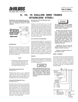
Exploded view of 83C & 83Z-210-CE Pressure Tank
24
EN
SB-E-21-041-R1 (2/2018) 5 / 6 www.carlisleft.com

© ITW Finishing Systems & Products 2009 Page 6
Ref.
No.
Part No. Description Individual
Parts Req.
28 KK-4977 Repair Kit 1
+ 29 ——– “O” Ring 1
+ 30 ——– Spring 1
+ 31 ——– “O” Ring 1
+ 32 ——– Valve 1
+ 33 ——– “O” Ring 1
+ 34 ——– Diaphragm Assembly 1
Ref. 10 HAR-511 REGULATOR ASSEMBLIES
Service Checks
Condition Cause Correction
Air escaping from port on
Regulator cap
Broken or damaged diaphragm
(ref No. 34)
Replace diaphragm
Pressure creepage registered on
gauge
Dirty or worn valve seat in
regulator
Clean or replace valve seat
Air leakage from Safety Valve
below maximum working pressure
The Valve seat is dirty or
damaged, or the valve stem assy
is seized
Replace Safety Valve. Do not
attempt to repair.
Fluid or air leak at Lid Gasket Defective Lid Gasket (ref. No. 2)
Thumb Screws not sufficiently
tight
Replace gasket
Tighten Screws
Note: Occasionally check gauge (Ref. No. 9). The needle should return to zero with no pressure on
the gauge.
ACCESSORIES
PT-78-K10 & PT-78-K60 Liner.
A moulded
polyethylene
tank liner to
reduce tank
clean up time.
The liner is
made of tough,
durable,
leakproof
polyethylene
and can be re-
used. May be used with all
materials that are compatible with
polyethylene. (Available in
packages of 10 and 60 only.)
PT-413 Air Regulator Kit.
Used to convert single regulated
tanks (fluid only), to dual
regulation (fluid and air). Used
with portable air compressors or
with air lines when no other
means (air transformers or
regulators) of air pressure
regulation is available.
Ball Valves.
To add a Ball valve to the Air
Inlet, remove Nipple (ref. No. 29).
Replace with Ball Valve VA-5432-
K (NPS) or VA-5427-K (BSP).
VA-540 Fluid outlet shut-off
valve. To install, remove the
adapter (Ref. No. 16), replace
with Ball valve VA-5429-K (BSP)
or VA-5424-K (NPS) (taper thread
to regulator).
Using these valves will simplify
attachment of air and fluid hoses.
EN
SB-E-21-041-R1 (2/2018)6 / 6www.carlisleft.com

© ITW Finishing Systems & Products 2009 Page 52
Ref.
nr.
Delnr. Beskrivelse Antal krævede
dele
1 PT-423 Tankkit (omf. ref.nr. 1A, 13, 14, 15 og 16) 1
1A PT-420 Tankens yderklædning 1
2 PT-33-1 Dækselpakning, santopren 1
3
PT-426 83C Dæksel, galvaniseret 1
PT-422 83Z Dæksel, rustfrit stål 1
4 83-2727 Manometer 1
5 HAR-511 Regulator 1
6 SSP-30-ZN 90° drejeadapter 1/4” NPS (F) x 1/4” NPT (M) 1
7 Kors 1/4” NPT (F) 1
8 TIA-5080-CE Sikkerhedsventil – 80 psi 1
9 PT-32 Håndtag 1
10 Sekskantmøtrik 3/8” – 16 1
11
AD-11
83C
(NPT)
Nippel 3/8” NPT (M) x 3/8” NPT (M) 1
2101007
83C
(BSP)
Nippel 3/8” NPT (M) x 3/8” BPS (M) 1
SSP-459
83Z
(NPT)
Nippel 3/8” NPT (M) x 3/8” NPT (M) rustfrit stål 1
CT-1164
83Z
(BSP)
Nippel 3/8” NPT (M) x 3/8” BSP (M) rustfrit stål 1
12 SSP-1939 Rørbøjning 3/8” NPT (F) x 3/8” (M) rustfrit stål 1
13 PT-79 Fingerskrue 4
14 ———— Gaffel 4
15 ———— Splitpind, 3/32 x 1” 4
16 ————- Hængselpind 4
17 PT-31 83C Væskeslange 1
17 QMS-9-1 83Z Væskeslange, rustfrit stål 1
18
PT-78-K10 eller
PT-78-K60
Tankindsats (sæt med 10 eller 60) 1
19 SSP-462-ZN Brystnippel 1/4” NPT (M) 1
20 SS-2707 Luftudløsningsventil 1
21 83-4233 DM-nippel (83C-210) 1
22
H-2008 (NPS) Nippel 1/4” NPT (M) x 1/4” NPS (M) 1
2101004 (BSP) Nippel 1/4” NPT (M) x 1/4” BSP (M) 1
83-4233 (NPS) Nippel 3/8” NPT (M) x 1/4” NPS (M) 1
2101005 (BSP) Nippel 3/8” NPT (M) x 1/4” BSP (M) 1
23
24 85-451 Air indstillingsenhed 1
DA
SB-E-21-041-R1 (2/2018)DA-4 / 6www.carlisleft.com

© ITW Finishing Systems & Products 2009 Page 34
Nº ref. Pieza Nº Descripción Nº piezas nece-
sarias
1 PT-423
Kit de recipiente (Incluye las piezas 1A, 13, 14,
15 y 16)
1
1A PT-420 Carcasa del recipiente 1
2 PT-33-1 Junta de la tapa, santopreno 1
3
PT-426 83C Tapa, cincada 1
PT-422 83Z Tapa, acero inoxidable 1
4 83-2727 Manómetro 1
5 HAR-511 Regulador 1
6 SSP-30-ZN
Adaptador giratorio de 90° 1/4” NPS (H) x 1/4”
NPT (M)
1
7 Cruceta 1/4” NPT (H) 1
8 TIA-5080-CE Válvula de seguridad—80 psi 1
9 PT-32 Asa 1
10 Tuerca hexagonal 3/8” - 16 1
11
AD-11
83C
(NPT)
Racor 3/8” NPT (M) x 3/8” NPT (M) 1
2101007
83C
(BSP)
Racor 3/8” NPT (M) x 3/8” BPS (M) 1
SSP-459
83Z
(NPT)
Racor 3/8” NPT (M) x 3/8” NPT (M) Inox 1
CT-1164
83Z
(BSP)
Racor 3/8” NPT (M) x 3/8” BSP (M) Inox 1
12 SSP-1939
Codo mixto macho/hembra 3/8” NPT (H) x
3/8” (M) Inox
1
13 PT-79 Tornillo de mariposa 4
14 ———— Brazo 4
15 ———— Cuaveta, 3/32 x 1” 4
16 ————- Perno giratorio 4
17 PT-31 83C Tubo de fluido 1
17 QMS-9-1 83Z Tubo de fluido, Inox 1
18
PT-78-K10 o
PT-78-K60
Depósito interior desechable (kit de 10 ó 60) 1
19 SSP-462-ZN Racor hexagonal 1/4” NPT (M) 1
20 SS-2707 Válvula de alivio de aire 1
21 83-4233 Racor D.M (83Z-210) 1
22
H-2008 (NPS) Racor 1/4“ NPT (M) x 1/4” NPS (M) 1
2101004 (BSP) Racor 1/4“ NPT (M) x 1/4” BSP (M) 1
83-4233 (NPS) Racor 3/8“ NPT (M) x 1/4” NPS (M) 1
2101005 (BSP) Racor 3/8“ NPT (M) x 1/4” BSP (M) 1
23
24 85-451 Conjunto de control de aire 1
ES
SB-E-21-041-R1 (2/2018)ES-4 / 6www.carlisleft.com

© ITW Finishing Systems & Products 2009 Page 47
83C- ja 83Z-210-CE -painesäiliöiden räjäytyskuva
Ilman
tulo
Nesteen
lähtö
24
FI
SB-E-21-041-R1 (2/2018) FI-5 / 6 www.carlisleft.com

© ITW Finishing Systems & Products 2009 Page 22
Ref. Nr. Onderdeelnr: Beschrijving Vereiste
afzonderlijke
onderdelen
1 PT-423 Tank kit (omvat ref. nrs. 1A, 13, 14, 15 & 16) 1
1A PT-420 Wand 1
2 PT-33-1 Pakking van tankklep, santopreen 1
3
PT-426 83C Klep, verzinkt 1
PT-422 83Z Klep, roestvrij staal 1
4 83-2727 Meter 1
5 HAR-511 Regelaar 1
6 SSP-30-ZN 90° wartelverloopstuk 1/4" NPS (F) x 1/4" NPT (M) 1
7 Kruisverbindingsstuk 1/4" NPT (F) 1
8 TIA-5080-CE Veiligheidsklep - 80 psi 1
9 PT-32 Handgreep 1
10 Zeskantige moer 3/8" - 16 1
11
AD-11
83C
(NPT)
Nippel 3/8" NPT (M) x 3/8" NPT (M) 1
2101007
83C
(BSP)
Nippel 3/8" NPT (M) x 3/8" BSP (M) 1
SSP-459
83Z
(NPT)
Nippel 3/8" NPT (M) x 3/8" NPT (M) roestvrij staal 1
CT-1164
83Z
(BSP)
Nippel 3/8" NPT (M) x 3/8" BSP (M) roestvrij staal 1
12 SSP-1939 Knie 3/8" NPT (F) x 3/8" (M) roestvrij staal 1
13 PT-79 Vingerschroef 4
14 ———— Juk 4
15 ———— Borgpen, 3/32 x 1" 4
16 ————- Scharnierpen 4
17 PT-31 83C Vloeistofbuis 1
17 QMS-9-1 83Z Vloeistofbuis, roestvrij staal 1
18
PT-78-K10 of
PT-78-K60
Binnenzak voor tank (set van 10 of 60) 1
19 SSP-462-ZN Zeskantige nippel 1/4" NPT (M) 1
20 SS-2707 Ontluchtingsklep 1
21 83-4233 D.M nippel (83C-210) 1
22
H-2008 (NPS) Nippel 1/4“ NPT (M) x 1/4“ NPS (M) 1
2101004 (BSP) Nippel 1/4“ NPT (M) x 1/4“ BSP (M) 1
83-4233 (NPS) Nippel 3/8“ NPT (M) x 1/4“ NPS (M) 1
2101005 (BSP) Nippel 3/8“ NPT (M) x 1/4“ BSP (M) 1
23
24 85-451 Lucht regelsamenstel 1
NL
SB-E-21-041-R1 (2/2018)NL-4 / 6www.carlisleft.com

© ITW Finishing Systems & Products 2009 Page 23
Explosietekening van 83C & 83Z-210-CE druktank
Vloeistof uit
Lucht in
24
NL
SB-E-21-041-R1 (2/2018) NL-5 / 6 www.carlisleft.com

© ITW Finishing Systems & Products 2009 Page 40
Ref.nr Art.nr Beskrivning Antal delar som
behövs
1 PT-423
Tankenhet (inklusive ref.nr 1A, 13, 14, 15 och
16)
1
1A PT-420 Tankhölje 1
2 PT-33-1 Lockpackning, Santoprene 1
3
PT-426 83C Lock, förzinkat 1
PT-422 83Z Lock, rostfritt stål 1
4 83-2727 Manometer 1
5 HAR-511 Regulator 1
6 SSP-30-ZN 90° sviveladapter ¼” NPS (F) x ¼” NPT (M) 1
7 Kors ¼” NPT (F) 1
8 TIA-5080-CE Säkerhetsventil – 80 psi 1
9 PT-32 Handtag 1
10 Sexkantsmutter 3/8” – 16 1
11
AD-11
83C
(NPT)
Nippel 3/8” NPT (M) x 3/8” NPT (M) 1
2101007
83C
(BSP)
Nippel 3/8” NPT (M) x 3/8” BSP (M) 1
SSP-459
83Z
(NPT)
Nippel 3/8” NPT (M) x 3/8” NPT (M), rostfritt stål 1
CT-1164
83Z
(BSP)
Nippel 3/8” NPT (M) x 3/8” BSP (M), rostfritt stål 1
12 SSP-1939 Knärör 3/8” NPT (F) x 3/8” (M), rostfritt stål 1
13 PT-79 Vingskruv 4
14 ———— Okenhet 4
15 ———— Saxpinne, 3/32 x 1” 4
16 ————- Gångjärnstapp 4
17 PT-31 83C Vätskerör 1
17 QMS-9-1 83Z Vätskerör, rostfritt stål 1
18
PT-78-K10 eller
PT-78-K60
Tankliner (sats om 10 eller 60) 1
19 SSP-462-ZN Sexkantsnippel ¼” NPT (M) 1
20 SS-2707 Avluftningsventil 1
21 83-4233 DM-nippel (83C-210) 1
22
H-2008 (NPS) Nippel 1/4” NPT (M) x 1/4” NPS (M) 1
2101004 (BSP) Nippel 1/4” NPT (M) x 1/4” BSP (M) 1
83-4233 (NPS) Nippel 3/8” NPT (M) x 1/4” NPS (M) 1
2101005 (BSP) Nippel 3/8” NPT (M) x 1/4” BSP (M) 1
23
24 85-451 Luft justera aggregat 1
SV
SB-E-21-041-R1 (2/2018)SV-4 / 6www.carlisleft.com

SB-E-21-041-R1 (2/2018) 55 / 56 www.carlisleft.com

SB-E-21-041-R1 (2/2018)56 / 56www.carlisleft.com
WARRANTY POLICY
This product is covered by Carlisle Fluid Technologies’ materials and workmanship limited warranty.
The use of any parts or accessories, from a source other than Carlisle Fluid Technologies,
will void all warranties. Failure to reasonably follow any maintenance guidance provided
may invalidate any warranty.
For specic warranty information please contact Carlisle Fluid Technologies.
For technical assistance or to locate an authorized distributor,
contact one of our international sales and customer support locations.
Region Industrial/Automotive Automotive Renishing
Americas
Tel: 1-800-992-4657 Tel: 1-800-445-3988
Fax: 1-888-246-5732 Fax: 1-800-445-6643
Europe, Africa,
Middle East, India
Tel: +44 (0)1202 571 111
Fax: +44 (0)1202 573 488
China
Tel: +8621-3373 0108
Fax: +8621-3373 0308
Japan
Tel: +81 45 785 6421
Fax: +81 45 785 6517
Australia
Tel: +61 (0) 2 8525 7555
Fax: +61 (0) 2 8525 7575
Carlisle Fluid Technologies is a global leader in innovative nishing technologies.
Carlisle Fluid Technologies reserves the right to modify equipment specications without prior notice.
DeVilbiss
®
, Ransburg
®
, ms
®
, BGK
®
, and Binks
®
are registered trademarks of Carlisle Fluid Technologies, Inc.
©2018 Carlisle Fluid Technologies, Inc.
All rights reserved.
For the latest information about our products, visit www.carlisleft.com
/