Page is loading ...

Figure 1
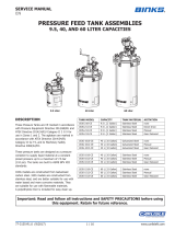
QMS-436 Double Regulation Conversion Kit
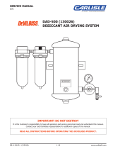
Figure 2
Typical Single Regulation
PURPOSE
For use where independent and accurate pressure
control of both air and fluid is essential. Used with
portable air compressors or with air lines when no other
means (air transformers or regulators) of air pressure
regulation is available.
INSTALLATION
To avoid blast of air when installing regulator on
tank or pump, always turn off air supply and
bleed off air in the tank by turning the air relief
valve thumb screw counterclockwise. Wait until
all the air has escaped before removing regulator.
Note
Use pipe sealant on all pipe thread connections.
1. Before removing regulators on tanks with air
motors, disconnect the air supply hose from the air
motor. Remove fluid pressure regulator at swivel
adapter. Refer to Figure 2.
2. Remove air outlet valve.
3. Install hex nipple (1, Figure 1) in right side of fluid
pressure regulator.
4. Install air pressure regulator (2) with gauge (3) on
D.M. nipple 1/4 x 3/8 universal pipe thread (1). Do not
turn gauge case by hand or with a tool. Use the stem
underneath the gauge case.
5. Install outlet valve in right side of air pressure reg-
ulator (2).
6. Close unused ports with the pipe plug supplied
with regulator.
7. Align assembly on tank air manifold and tighten
swivel adapter.
8. On tanks with air motors, reconnect the air supply
hose to the air motor.
9. Connect air supply hose to the air inlet valve.
10. Connect fluid hose from gun to air outlet on tank lid.
11. Connect air hose from gun to air outlet valve.
QMS-436 DOUBLE REGULATION CONVERSION KIT
SBBI-21-913-A
SERVICE BULLETIN
Replaces SB-21-913
Ref Replacement
No. Part Number Description Qty
1 83-4233 D.M. Nipple 1/4 x 3/8 Universal Pipe Thd. 1
2 HAR-507 Regulator 1
3 83-1355 Gauge, 100 lbs. 1
4— Pipe Plug
1/4 NPT (Supplied/Reg) 1
3
1
Air Outlet
Valve
Air Inlet
Valve
Fluid
Pressure
Regulator
Air
Manifold
on Tank
2
4
Air Outlet
Valve
HAR-511
Air Inlet
Valve
Swivel
Adapter
Gauge
Pipe Plug
Air
Manifold
on Tank
Bushing

PREVENTIVE MAINTENANCE
After each day’s use, relieve tension on regulators by
setting them at 0 pounds pressure and turning off the
main air supply. Refer to regulator service bulletin for
further maintenance.
Flow indicator arrows are on the back of the regulators.
Air flow should be in the direction shown when looking
at the back of the regulator.
OPERATION
1. Open air inlet valve and fluid outlet valve on tank lid.
2. Adjust fluid pressure, in usual manner, to flow
approximately one pint per minute.
3. Open air outlet valve.
4. Set air pressure regulator (2) approximately 20 to 30
pounds.
5. Test spray a small area.
A splattered effect indicates too much fluid pressure.
Decrease fluid pressure or increase air pressure.
Poor coverage and excessive overspray indicate too
much air pressure. Increase fluid pressure or decrease
air pressure.
PAGE 2 SBBI-21-913-A
2/02 © Copyright 2002, Binks Printed in U.S.A.
WARRANTY
This product is covered by Binks' 1 Year Limited Warranty.
Sales and Service Through a Nationwide Network of Industrial Distributors.
Customer Service in USA / 1-800-992-4657
Technical Support in USA / 1-888-992-4657
195 Internationale Blvd.
Glendale Heights, IL 60139
/